2014 NISSAN TEANA SEC
[x] Cancel search: SECPage 4649 of 4801

WCS
SYSTEMWCS-7
< SYSTEM DESCRIPTION >
C
D E
F
G H
I
J
K L
M B
A
O P
WARNING CANCEL CONDITIONS
Warning is canceled if any of the following conditions is fulfilled.• Lighting switch OFF
• Ignition switch ON
• Front door switch LH is OFF
SEAT BELT WARNING CHIME
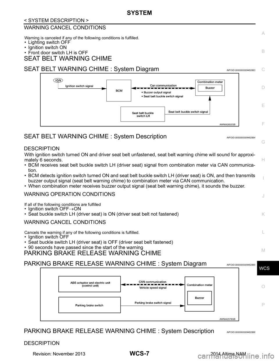
SEAT BELT WARNING CHIME : System DiagramINFOID:0000000009462883
SEAT BELT WARNING CHIME : System DescriptionINFOID:0000000009462884
DESCRIPTION
With ignition switch turned ON and driver seat belt unfastened, seat belt warning chime will sound for approxi-
mately 6 seconds.
• BCM receives seat belt buckle switch LH (driver seat) signal from combination meter via CAN communica- tion.
• BCM detects ignition switch turned ON and seat belt buckle switch LH (driver seat) is ON, and then transmits
buzzer output signal (seat belt warning chime) to combination meter via CAN communication.
• When combination meter receives buzzer output signal (seat belt warning chime), it sounds the buzzer.
WARNING OPERATION CONDITIONS
If all of the following conditions are fulfilled• Ignition switch OFF→ON
• Seat buckle switch LH (driver seat) is ON (driver seat belt not fastened)
WARNING CANCEL CONDITIONS
Cancels the warning if any of the following conditions is fulfilled.• Ignition switch OFF
• Seat buckle switch LH (driver seat) is OFF (driver seat belt fastened)
• 90 seconds have passed since the start of the warning
PARKING BRAKE RELEASE WARNING CHIME
PARKING BRAKE RELEASE WARNING CHIME : System DiagramINFOID:0000000009462885
PARKING BRAKE RELEASE WARNING CHIME : System DescriptionINFOID:0000000009462886
DESCRIPTION
AWNIA2652GB
AWNIA2578GB
Revision: November 20132014 Altima NAMRevision: November 20132014 Altima NAM
Page 4651 of 4801

WCS
DIAGNOSIS SYSTEM (METER)WCS-9
< SYSTEM DESCRIPTION >
C
D E
F
G H
I
J
K L
M B
A
O P
DIAGNOSIS SYSTEM (METER)
DescriptionINFOID:0000000009941189
COMBINATION METER SE LF-DIAGNOSIS MODE
The following meter functions can be checked during Combination Meter Self-Diagnosis Mode:
• Pointer sweep of speedometer, tachometer and gauges.
• Illumination of all LCD segments and color patterns for meter displays.
• Illumination of all lamps/LEDs that are controlled by the combination meter (regardless of switch status).
STARTING COMBINATION METER SELF-DIAGNOSIS MODE
NOTE:
• Check combination meter power supply and ground circuits if self-diagnosis mode does not start. Refer to
MWI-58, "COMBINATION METER : Diagnosis Procedure"
. Replace combination meter if power supply and
ground circuits are found to be normal and self-diagnosis mode does not start. Refer to MWI-82, "Removal
and Installation".
• Combination meter self-diagnosis mode will function with the ignition switch in ON. Combination meter self-
diagnosis mode will exit upon turning the ignition switch to OFF.
How to Initiate Se lf-Diagnosis Mode
1. Press and hold the trip reset switch while turning the ignition switch ON. After 2 seconds release trip reset
switch, then press the trip reset switch 3 times withi n 7 seconds after the ignition switch is turned ON.
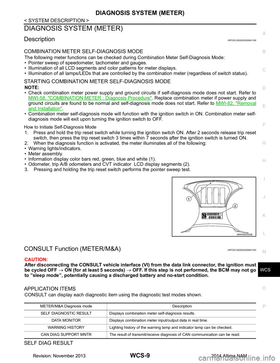
2. When the diagnosis function is activated, the meter illuminates all of the following:
• Warning lights/indicators.
• Meter assembly.
• Information display color bars red, green, blue and white (1).
• Odometer, trip A/B odometers and CVT indicator LCD display segments (2).
3. Pressing and holding the trip reset switch performs the pointer sweep test.
CONSULT Function (METER/M&A)INFOID:0000000009941190
CAUTION:
After disconnecting the CONSULT vehicle interface (VI) from the data link connector, the ignition must
be cycled OFF → ON (for at least 5 seconds) → OFF. If this step is not performed, the BCM may not go
to ”sleep mode”, potentiall y causing a discharged battery and no-start condition.
APPLICATION ITEMS
CONSULT can display each diagnostic item using the diagnostic test modes shown.
SELF DIAG RESULT
AWNIA2543GB
METER/M&A Diagnosis mode Description
SELF DIAGNOSTIC RESULT Displays combination meter self-diagnosis results. DATA MONITOR Displays combination meter input/output data in real time.
WARNING HISTORY Lighting history of the warning lamp and indicator lamp can be checked.
CAN DIAG SUPPORT MNTR The result of transmit/receive diagnosis of CAN communication can be read.
Revision: November 20132014 Altima NAMRevision: November 20132014 Altima NAM
Page 4654 of 4801

WCS-12
< SYSTEM DESCRIPTION >
DIAGNOSIS SYSTEM (METER)
SPECIAL FUNCTION
Special menu
W/L ON HISTORY
• “W/L ON HISTORY” indicates the “TIME” w hen the warning/ indicator lamp is turned on.
• The “TIME” above is:
- 0: The condition that the warning/indicator lamp has been turned on 1 or more times after starting the engine
and waiting for 30 seconds.
- 1 - 39: The number of times the engine was restarted after the 0 condition.
- NO W/L ON HISTORY: No warning/ indicator lamp history is stored.
NOTE:
• W/L ON HISTORY is not stored for approximately 30 seconds after the engine starts.
• Brake warning lamp does not store any history when the parking brake is applied or the brake fluid level gets
low.
LDW IND
[ON/OFF] Displays [ON/OFF] condition of LDW warning indicator message in the informa-
tion display.
TPMS MALF
[ON/OFF] Displays [ON/OFF] condition of TPMS warning indicator.
Display item [Unit]
MAIN
SIGNALS Description
Display item Description
W/L ON HISTORY Lighting history of warning lamp and indicator lamp can be checked.
Revision: November 20132014 Altima NAMRevision: November 20132014 Altima NAM
Page 4655 of 4801

WCS
DIAGNOSIS SYSTEM (BCM)WCS-13
< SYSTEM DESCRIPTION >
C
D E
F
G H
I
J
K L
M B
A
O P
DIAGNOSIS SYSTEM (BCM)
COMMON ITEM
COMMON ITEM : CONSULT Function (BCM - COMMON ITEM)INFOID:0000000009941192
CAUTION:
After disconnecting the CONSULT vehicle interface (VI) from the data link connector, the ignition must
be cycled OFF → ON (for at least 5 seconds) → OFF. If this step is not performed, the BCM may not go
to ”sleep mode”, potentiall y causing a discharged battery and a no-start condition.
APPLICATION ITEM
CONSULT performs the following functions via CAN communication with BCM.
SYSTEM APPLICATION
BCM can perform the following functions.
Direct Diagnostic Mode Description
Ecu Identification The BCM part number is displayed.
Self Diagnostic Result The BCM self diagnostic results are displayed.
Data Monitor The BCM input/output data is displayed in real time.
Active Test The BCM activates outputs to test components.
Work support The settings for BCM functions can be changed.
Configuration • The vehicle specification can be read and saved.
• The vehicle specification can be written when replacing BCM.
CAN Diag Support Mntr The result of transmit/receive diagnosis of CAN communication is displayed.
System Sub System Direct Diagnostic Mode
Ecu Identification
Self Diagnostic Result
Data Monitor
Active Test
Work support
Configuration
CAN Diag Su pport Mntr
Door lock DOOR LOCK ××××
Rear window defogger REAR DEFOGGER ×××
Warning chime BUZZER ××
Interior room lamp timer INT LAMP ×××
Remote keyless entry system MULTI REMOTE ENT ×××
Exterior lamp HEADLAMP ×××
Wiper and washer WIPER ×××
Turn signal and hazard warning lamps FLASHER ××
Air conditioner AIR CONDITIONER ×
Intelligent Key system INTELLIGENT KEY ××××
Combination switch COMB SW ×
BCM BCM × × ×××
Immobilizer IMMU ×××
Interior room lamp battery saver BATTERY SAVER ××
Trunk open TRUNK ×
Vehicle security system THEFT ALM ×××
Revision: November 20132014 Altima NAMRevision: November 20132014 Altima NAM
Page 4656 of 4801

WCS-14
< SYSTEM DESCRIPTION >
DIAGNOSIS SYSTEM (BCM)
BUZZER
BUZZER : CONSULT Function (BCM - BUZZER)INFOID:0000000009941193
CAUTION:
After disconnecting the CONSULT vehicle interface (VI) from the data link connector, the ignition must
be cycled OFF → ON (for at least 5 seconds) → OFF. If this step is not performed, the BCM may not go
to ”sleep mode”, potentially causing a di scharged battery and a no-start condition.
DATA MONITOR
ACTIVE TEST
RAP system RETAINED PWR ×
Signal buffer system SIGNAL BUFFER ×
TPMS AIR PRESSURE MONITOR ××××
System Sub System
Direct Diagnostic Mode
Ecu Identification
Self Diagnostic Result
Data Monitor
Active Test
Work support
Configuration
CAN Diag Support Mntr
Monitor Item [Unit] Description
PUSH -SW [On/Off] Indicates condition of push-button ignition switch.
UNLK SEN -DR [On/Off] Indicates condition of door unlock sensor.
VEH SPEED 1 [km/h] Indicates vehicle speed signal received from ABS on CAN communication line.
TAIL LAMP SW [On/Off] Indicates condition of combination switch.
FR FOG SW [On/Off] Indicates condition of front fog lamp switch.
DOOR SW-DR [On/Off] Indicates condition of front door switch LH.
CDL LOCK SW [On/Off] Indicates condition of lock signal from door lock and unlock switch.
Test Item Description
SEAT BELT WARN TEST This test is able to check seat belt warning chime operation [On/Off].
LIGHT WARN ALM This test is able to check light warning chime operation [On/Off].
REVERSE WARNING This test is able to check reverse warning chime operation [On/Off].
ID REGIST WARNING This test is able to check TPMS transmitter ID regist warning chime operation [On/Off].
Revision: November 20132014 Altima NAMRevision: November 20132014 Altima NAM
Page 4676 of 4801

WT-1
SUSPENSION
C
D
F
G H
I
J
K L
M
SECTION WT
A
B
WT
N
O PCONTENTS
ROAD WHEELS & TIRES
PRECAUTION ................ ...............................3
PRECAUTIONS .............................................. .....3
Precaution for Supplemental Restraint System
(SRS) "AIR BAG" and "SEAT BELT PRE-TEN-
SIONER" ............................................................. ......
3
Service Notice and Precautions for TPMS ................3
Precaution for Road Wheel .......................................4
PREPARATION ............................................5
PREPARATION .............................................. .....5
Special Service Tool ........................................... ......5
Commercial Service Tool ..........................................5
SYSTEM DESCRIPTION ..............................6
COMPONENT PARTS ................................... .....6
Component Parts Location .................................. ......6
Component Description .............................................6
BCM ..........................................................................6
Transmitter ................................................................7
Remote Keyless Entry Receiver ...............................7
Outside Key Antennas ..............................................7
Combination Meter ....................................................7
SYSTEM ..............................................................8
System Diagram .................................................. ......8
System Description ...................................................9
Easy Fill Tire Alert Function ......................................9
DIAGNOSIS SYSTEM (BCM) ............................10
COMMON ITEM ..................................................... ....10
COMMON ITEM : CONSULT Function (BCM -
COMMON ITEM) ................................................. ....
10
AIR PRESSURE MONITOR ......................................11
AIR PRESSURE MONITOR : CONSULT Function
(BCM-AIR PRESSURE MO NITOR) ........................
11
ECU DIAGNOSIS INFORMATION ........... ...13
BCM ...................................................................13
List of ECU Reference ......................................... ....13
WIRING DIAGRAM ......................................14
TIRE PRESSURE MONITORING SYSTEM ......14
Wiring Diagram - With Individual Tire Pressure
Display ................................................................. ....
14
Wiring Diagram - Without Individual Tire Pressure
Display ................................................................. ....
20
BASIC INSPECTION ...................................24
DIAGNOSIS AND REPAIR WORK FLOW .......24
Work Flow ............................................................ ....24
ID REGISTRATION PROCEDURE ...................25
Description ...............................................................25
Work Procedure .......................................................25
DTC/CIRCUIT DIAGNOSIS .........................28
C1704, C1705, C1706, C1707 LOW TIRE
PRESSURE .......................................................
28
DTC Logic ............................................................ ....28
Diagnosis Procedure ...............................................28
C1708, C1709, C1710, C1711 TRANSMITTER
(NO DATA) ........................................................
30
DTC Logic ............................................................ ....30
Diagnosis Procedure ...............................................30
C1712, C1713, C1714, C1715 TRANSMITTER
(CHECKSUM) ....................................................
33
DTC Logic ............................................................ ....33
Diagnosis Procedure ...............................................33
C1716, C1717, C1718, C1719 TRANSMITTER
(PRESSURE DATA) ..........................................
35
DTC Logic ............................................................ ....35
Diagnosis Procedure ...............................................35
Revision: November 20132014 Altima NAMRevision: November 20132014 Altima NAM
Page 4678 of 4801

PRECAUTIONSWT-3
< PRECAUTION >
C
D
F
G H
I
J
K L
M A
B
WT
N
O P
PRECAUTION
PRECAUTIONS
Precaution for Supplemental Restraint System (SRS) "AIR BAG" and "SEAT BELT
PRE-TENSIONER"
INFOID:0000000009951708
The Supplemental Restraint System such as “A IR BAG” and “SEAT BELT PRE-TENSIONER”, used along
with a front seat belt, helps to reduce the risk or severi ty of injury to the driver and front passenger for certain
types of collision. Information necessary to service t he system safely is included in the SR and SB section of
this Service Manual.
WARNING:
• To avoid rendering the SRS inoper ative, which could increase the risk of personal injury or death in
the event of a collision which would result in air bag inflation, all maintenance must be performed by
an authorized NISSAN/INFINITI dealer.
• Improper maintenance, including in correct removal and installation of the SRS, can lead to personal
injury caused by unintentional act ivation of the system. For removal of Spiral Cable and Air Bag
Module, see the SR section.
• Do not use electrical test equipm ent on any circuit related to the SRS unless instructed to in this
Service Manual. SRS wiring harnesses can be identi fied by yellow and/or orange harnesses or har-
ness connectors.
PRECAUTIONS WHEN USING POWER TOOLS (AIR OR ELECTRIC) AND HAMMERS
WARNING:
• When working near the Airbag Diagnosis Sensor Un it or other Airbag System sensors with the Igni-
tion ON or engine running, DO NOT use air or el ectric power tools or strike near the sensor(s) with a
hammer. Heavy vibration could activate the sensor( s) and deploy the air bag(s), possibly causing
serious injury.
• When using air or electric power tools or hammers , always switch the Ignition OFF, disconnect the
battery and wait at least three mi nutes before performing any service.
Service Notice and Precautions for TPMSINFOID:0000000009464472
WARNING:
Radio waves could adversely affect electrical medi cal equipment. Those who use a pacemaker should
contact the electrical medical equipment manu facturer for possible influences before use.
• Low tire pressure warning lamp blinks for 1 minute, then turns ON when any malfunction occurs except low
tire pressure. Erase the self-diagnosis memories for Tire Pressure Monitoring System (TPMS), or register
the ID to turn low tire pressure warning lamp OFF. For ID registration, refer to WT-25, "Work Procedure"
.
• ID registration is required when replacing or rotating wheels, replacing tire pressure sensor or BCM. Refer to WT-25, "Work Procedure"
.
• For easy fill tire alert function, refer to the following. WT-9, "Easy Fill Tire Alert Function"
- When inflating the tires, park the vehicle in the safe area and ensure the safety of the working area.
- Read and understand the easy fill tire alert function prior to use.
- Inflate the tires one at a time.
- If there is no response for approximately 15 seconds or mo re after inflating the tires, cancel the use of the
easy fill tire alert function or move the vehicle approximately 1 m (3.2 ft) backward or forward to try again.
The air filler pressure may be weak or out of service area.
- Despite the high-precision TPMS pressure sensor, an i ndicated value may differ from that of the pressure
gauge.
- Air pressure is measured rather high due to the rise in tire air temperature after driving.
- If TPMS is malfunctioning, the easy fill tire alert is unusable.
• Replace grommet seal, valve core and valve cap of tire pressure sensor in TPMS when replacing each tire
by reaching the wear limit. Refer to WT-57, "Exploded View"
.
• Because the tire pressure sensor conforms to No rth America radio law, the following items must be
observed.
- The sensor may be used only in North America.
- It may not be used in any method other than the specified method.
- It must not be disassembled or modified.
Revision: November 20132014 Altima NAMRevision: November 20132014 Altima NAM
Page 4684 of 4801

SYSTEMWT-9
< SYSTEM DESCRIPTION >
C
D
F
G H
I
J
K L
M A
B
WT
N
O P
System DescriptionINFOID:0000000009464484
When the vehicle has reached a speed of 40 km/h (25 MPH) or greater, the BCM receives a signal transmitted
from the tire pressure sensors/transmitters installed in each wheel. If the BCM detects low inflation pressure or
a system malfunction, it sends a signal to the combi nation meter via CAN communication to illuminate the low
tire pressure warning lamp. In addition, a warning message will be displayed in the vehicle information display.
Refer to the Owner’s Manual for additional information.
The tire pressure monitoring system (TPMS) has Easy fill ti re alert function to aid in tire inflation. Refer to WT-
9, "Easy Fill Tire Alert Function".
Low Tire Pressure Warning Lamp and Display Indications
Easy Fill Tire Alert FunctionINFOID:0000000009464485
NOTE:
When beginning tire inflation, it takes a few seconds for t he Easy fill tire alert to function. If there is no
response for approximately 15 seconds or more, cancel t he Easy fill tire alert function and move the vehicle
approximately 1 m (3.2 ft) backward or forward to try again.
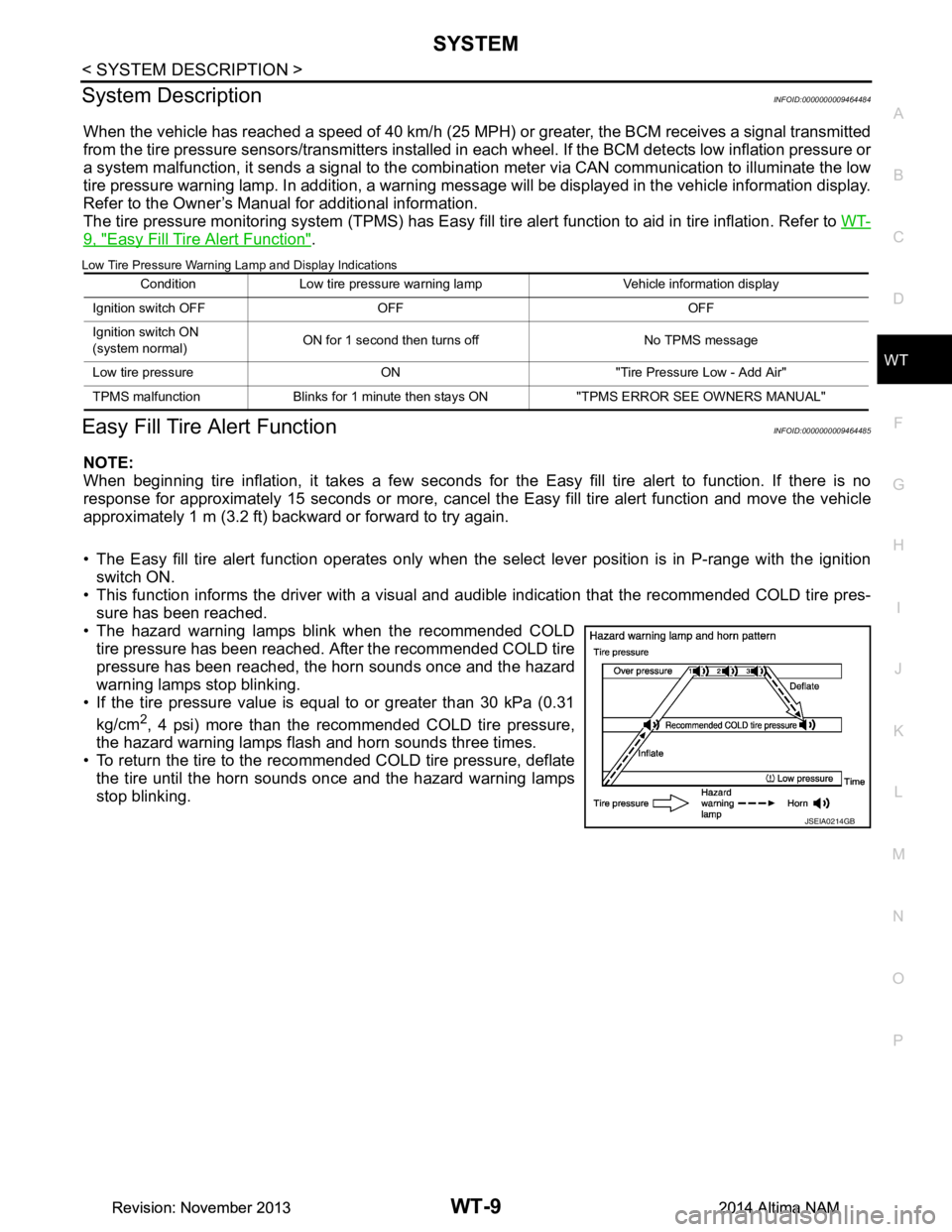
• The Easy fill tire alert function operates only when t he select lever position is in P-range with the ignition
switch ON.
• This function informs the driver with a visual and audible indication that the recommended COLD tire pres-
sure has been reached.
• The hazard warning lamps blink when the recommended COLD tire pressure has been reached. After the recommended COLD tire
pressure has been reached, the horn sounds once and the hazard
warning lamps stop blinking.
• If the tire pressure value is equal to or greater than 30 kPa (0.31
kg/cm
2, 4 psi) more than the recommended COLD tire pressure,
the hazard warning lamps flash and horn sounds three times.
• To return the tire to the recommended COLD tire pressure, deflate
the tire until the horn sounds once and the hazard warning lamps
stop blinking.
Condition Low tire pressure warning lamp Vehicle information display
Ignition switch OFF OFF OFF
Ignition switch ON
(system normal) ON for 1 second then turns off No TPMS message
Low tire pressure ON "Tire Pressure Low - Add Air"
TPMS malfunction Blinks for 1 minute th en stays ON "TPMS ERROR SEE OWNERS MANUAL"
JSEIA0214GB
Revision: November 20132014 Altima NAMRevision: November 20132014 Altima NAM