2014 NISSAN TEANA key
[x] Cancel search: keyPage 881 of 4801

OUTSIDE KEY ANTENNA (REAR BUMPER)DLK-113
< DTC/CIRCUIT DIAGNOSIS >
C
D E
F
G H
I
J
L
M A
B
DLK
N
O P
OUTSIDE KEY ANTENN A (REAR BUMPER)
Component Function CheckINFOID:0000000009461842
1.CHECK OUTSIDE KEY ANTENNA (REAR BUMPER)
1. Place the Intelligent Key into the detection area of the outside key antenna (rear bumper).
2. Press the door request switch (trunk).
Does the door unlock?
YES >> Inspection End.
NO >> Refer to DLK-113, "Diagnosis Procedure"
.
Diagnosis ProcedureINFOID:0000000009461843
Regarding Wiring Diagram information, refer to DLK-61, "Wiring Diagram".
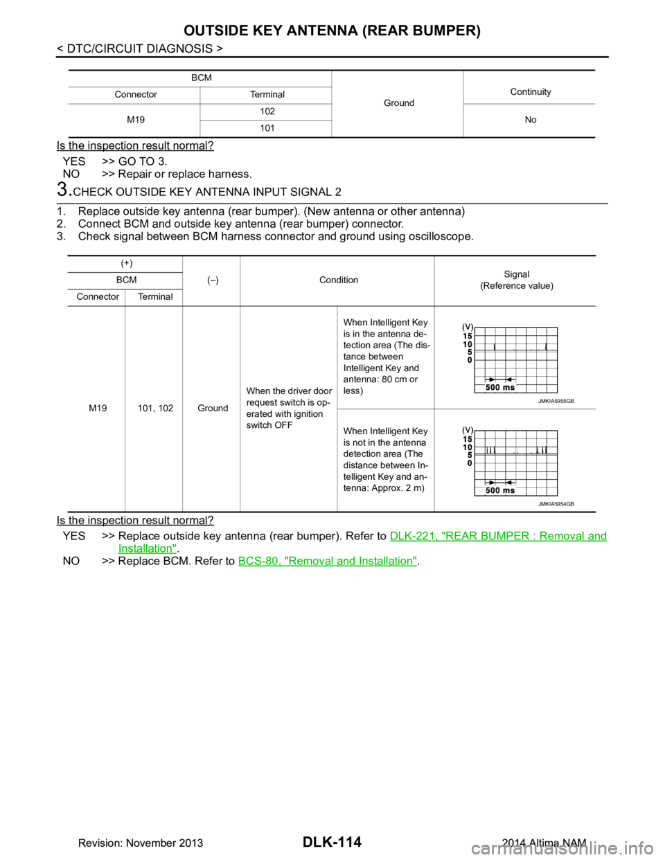
1.CHECK OUTSIDE KEY ANTENNA INPUT SIGNAL 1
1. Turn ignition switch OFF.
2. Check signal between BCM harness connector and ground using oscilloscope.
Is the inspection result normal?
YES >> Replace BCM. Refer to BCS-80, "Removal and Installation".
NO >> GO TO 2.
2.CHECK OUTSIDE KEY ANTENNA CIRCUIT
1. Disconnect BCM connector and outside key antenna (rear bumper) connector.
2. Check continuity between BCM harness connecto r and outside key antenna (rear bumper) harness con-
nector.
3. Check continuity between BCM harness connector and ground.
(+) (–) Condition Signal
(Reference value)
BCM
Connector Terminal
M19 101, 102 Ground When the driver door
request switch is op-
erated with ignition
switch OFF When Intelligent Key
is in the antenna de-
tection area (The dis-
tance between
Intelligent Key and
antenna: 80 cm or
less)
When Intelligent Key
is not in the antenna
detection area (The
distance between In-
telligent Key and an-
tenna: Approx. 2 m)
JMKIA5955GB
JMKIA5954GB
BCM Outside key antenna (rear bumper) Continuity
Connector Terminal Connector Terminal
M19 102
B46 1
Ye s
101 2
Revision: November 20132014 Altima NAMRevision: November 20132014 Altima NAM
Page 882 of 4801

DLK-114
< DTC/CIRCUIT DIAGNOSIS >
OUTSIDE KEY ANTENNA (REAR BUMPER)
Is the inspection result normal?
YES >> GO TO 3.
NO >> Repair or replace harness.
3.CHECK OUTSIDE KEY ANTENNA INPUT SIGNAL 2
1. Replace outside key antenna (rear bumper). (New antenna or other antenna)
2. Connect BCM and outside key antenna (rear bumper) connector.
3. Check signal between BCM harness connector and ground using oscilloscope.
Is the inspection result normal?
YES >> Replace outside key antenna (rear bumper). Refer to DLK-221, "REAR BUMPER : Removal and
Installation".
NO >> Replace BCM. Refer to BCS-80, "Removal and Installation"
.
BCM
GroundContinuity
Connector Terminal
M19 102
No
101
(+)
(–) Condition Signal
(Reference value)
BCM
Connector Terminal
M19 101, 102 Ground When the driver door
request switch is op-
erated with ignition
switch OFF When Intelligent Key
is in the antenna de-
tection area (The dis-
tance between
Intelligent Key and
antenna: 80 cm or
less)
When Intelligent Key
is not in the antenna
detection area (The
distance between In-
telligent Key and an-
tenna: Approx. 2 m)
JMKIA5955GB
JMKIA5954GB
Revision: November 20132014 Altima NAMRevision: November 20132014 Altima NAM
Page 883 of 4801

KEY CYLINDER SWITCHDLK-115
< DTC/CIRCUIT DIAGNOSIS >
C
D E
F
G H
I
J
L
M A
B
DLK
N
O P
KEY CYLINDER SWITCH
DescriptionINFOID:0000000009461844
For vehicles equipped with LH and RH anti-pinch system, the main power window and door lock/unlock switch
detects condition of the door key cylinder switch and transmits to BCM as the LOCK or UNLOCK signal.
For vehicles equipped with LH anti-pinch system only, t he front door lock assembly LH (key cylinder switch)
transmits the LOCK or UNLOCK signal directly to the BCM.
Component Function CheckINFOID:0000000009461845
1.CHECK DOOR KEY CYLINDER SWITCH INPUT SIGNAL
Check KEY CYL UN-SW, KEY CYL UN-SW in “DATA MO NITOR” mode for “POWER DOOR LOCK SYSTEM”
with CONSULT. Refer to DLK-81, "Work Flow"
.
Is the inspection result normal?
YES >> Key cylinder switch is OK.
NO >> With LH and RH anti-pinch, refer to DLK-115, "Diagnosis Procedure (With LH and RH Anti-
Pinch)".
NO >> With LH anti-pinch only, refer to DLK-116, "Diagnosis Procedure (With LH Anti-Pinch Only)"
.
Diagnosis Procedure (With LH and RH Anti-Pinch)INFOID:0000000009461846
Regarding Wiring Diagram information, refer to DLK-51, "Wiring Diagram".
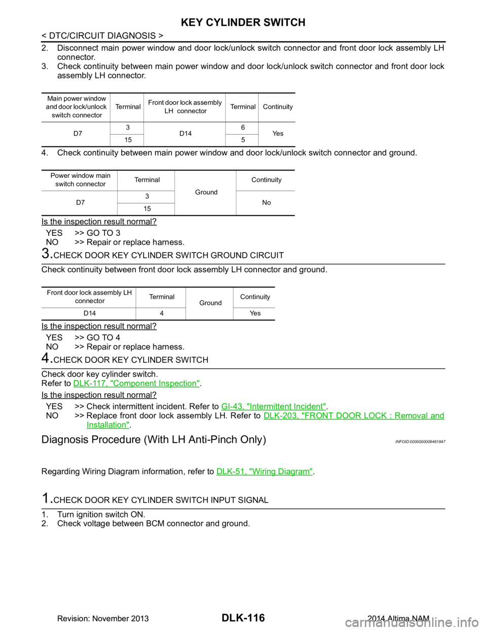
1.CHECK DOOR KEY CYLINDER SWITCH INPUT SIGNAL
1. Turn ignition switch ON.
2. Check voltage between main power window and door lock/unlock switch connector and ground.
Is the inspection result normal?
YES >> Replace main power window and door lock/unlock switch. Refer to PWC-142, "Removal and
Installation".
NO >> GO TO 2
2.CHECK DOOR KEY CYLINDER SIGNAL CIRCUIT
1. Turn ignition switch OFF.
Monitor item Condition
KEY CYL LK-SW Lock : ON
Neutral / Unlock : OFF
KEY CYL UN-SW Unlock : ON
Neutral / Lock : OFF
Te r m i n a l s
Key positionVoltage (V)
(Approx.)
(+)
(–)
Main power window
and door lock/unlock switch connector Te r m i n a l
D7 3
Ground Lock 0
Neutral / Unlock 5
15 Unlock 0
Neutral / Lock 5
Revision: November 20132014 Altima NAMRevision: November 20132014 Altima NAM
Page 884 of 4801

DLK-116
< DTC/CIRCUIT DIAGNOSIS >
KEY CYLINDER SWITCH
2. Disconnect main power window and door lock/unlock switch connector and front door lock assembly LHconnector.
3. Check continuity between main power window and door lock/unlock switch connector and front door lock
assembly LH connector.
4. Check continuity between main power window and door lock/unlock switch connector and ground.
Is the inspection result normal?
YES >> GO TO 3
NO >> Repair or replace harness.
3.CHECK DOOR KEY CYLINDER SWITCH GROUND CIRCUIT
Check continuity between front door lock assembly LH connector and ground.
Is the inspection result normal?
YES >> GO TO 4
NO >> Repair or replace harness.
4.CHECK DOOR KEY CYLINDER SWITCH
Check door key cylinder switch.
Refer to DLK-117, "Component Inspection"
.
Is the inspection result normal?
YES >> Check intermittent incident. Refer to GI-43, "Intermittent Incident".
NO >> Replace front door lock assembly LH. Refer to DLK-203, "FRONT DOOR LOCK : Removal and
Installation".
Diagnosis Procedure (With LH Anti-Pinch Only)INFOID:0000000009461847
Regarding Wiring Diagram information, refer to DLK-51, "Wiring Diagram".
1.CHECK DOOR KEY CYLINDER SWITCH INPUT SIGNAL
1. Turn ignition switch ON.
2. Check voltage between BCM connector and ground.
Main power window
and door lock/unlock
switch connector Te r m i n a l
Front door lock assembly
LH connector Terminal Continuity
D7 3
D14 6
Ye s
15 5
Power window main switch connector Terminal
GroundContinuity
D7 3
No
15
Front door lock assembly LH
connector Terminal
GroundContinuity
D14 4 Yes
Revision: November 20132014 Altima NAMRevision: November 20132014 Altima NAM
Page 885 of 4801

KEY CYLINDER SWITCHDLK-117
< DTC/CIRCUIT DIAGNOSIS >
C
D E
F
G H
I
J
L
M A
B
DLK
N
O P
Is the inspection result normal?
YES >> Replace front door lock assembly LH. Refer to PWC-65, "Removal and Installation".
NO >> GO TO 2
2.CHECK DOOR KEY CYLINDE R SWITCH GROUND CIRCUIT
1. Turn ignition switch OFF.
2. Disconnect front door lock assembly LH connector.
3. Check continuity between front door lock assembly LH connector and ground.
Is the inspection result normal?
YES >> GO TO 3
NO >> Repair or replace harness.
3.CHECK DOOR KEY CYLINDER SIGNAL CIRCUIT
1. Disconnect BCM connector M18 and M17.
2. Check continuity between front door lock assembly LH connector and BCM connector M18 or M17.
3. Check continuity between front door lock assembly LH connector and ground.
Is the inspection result normal?
YES >> GO TO 4
NO >> Repair or replace harness.
4.CHECK DOOR KEY CYLINDER SWITCH
Check door key cylinder switch.
Refer to DLK-117, "Component Inspection"
.
Is the inspection result normal?
YES >> Check intermittent incident. Refer to GI-43, "Intermittent Incident".
NO >> Replace front door lock assembly LH. Refer to DLK-203, "FRONT DOOR LOCK : Removal and
Installation".
Component InspectionINFOID:0000000009461848
COMPONENT INSPECTION
Te r m i n a l s
Key positionVoltage (V)
(Approx.)
(+)
(–)
BCM connector Terminal
M18 74 GroundLock 0
Neutral / Unlock 5
M17 24 Unlock 0
Neutral / Lock 5
Front door lock assembly LH connector Terminal
GroundContinuity
D14 4 Yes
Front door lock assembly LH connector Terminal BCM connector Terminal Continuity
D14 5M1724
Ye s
6M1874
Front door lock assembly LH connector Te r m i n a l
GroundContinuity
D14 5
No
6
Revision: November 20132014 Altima NAMRevision: November 20132014 Altima NAM
Page 886 of 4801

DLK-118
< DTC/CIRCUIT DIAGNOSIS >
KEY CYLINDER SWITCH
1.CHECK DOOR KEY CYLINDER SWITCH
Check front door lock assembly LH.
Is the inspection result normal?
YES >> Key cylinder switch is OK.
NO >> Replace front door lock assembly LH. Refer to DLK-203, "FRONT DOOR LOCK : Removal and
Installation".
Te r m i n a l
Key position Continuity
Front door lock assembly LH (key
cylinder switch) connector
5 4 Unlock Yes
Neutral / Lock No
6 Lock Yes
Neutral / Unlock No
Revision: November 20132014 Altima NAMRevision: November 20132014 Altima NAM
Page 890 of 4801

DLK-122
< DTC/CIRCUIT DIAGNOSIS >
TRUNK LID OPENER SWITCH
TRUNK LID OPENER SWITCH
DescriptionINFOID:0000000009461853
Transmits trunk lid open signal to BCM.
Component Function CheckINFOID:0000000009461854
1.CHECK FUNCTION
With CONSULT
Check trunk lid opener switch TR/BD OPEN SW in Data Monitor mode with CONSULT.
• When trunk lid opener switch is turned to “ON”.
Is the inspection result normal?
YES >> Trunk lid opener switch is OK.
NO >> Refer to DLK-122, "Diagnosis Procedure"
.
Diagnosis ProcedureINFOID:0000000009461855
Regarding Wiring Diagram information, refer to DLK-77, "Wiring Diagram".
1.CHECK TRUNK LID OPEN INPUT SIGNAL
1. Remove Intelligent Key from key slot.
2. Press trunk lid opener switch.
3. Check voltage between BCM connector and ground.
Is the inspection result normal?
YES >> GO TO 5
NO >> GO TO 2
2.CHECK TRUNK LID OPENER SWITCH CIRCUIT
1. Disconnect BCM connector.
2. Check continuity between BCM connector and trunk lid opener switch connector.
3. Check continuity between BCM connector and ground.
Is the inspection result normal?
Monitor item Condition
TR/BD OPEN SW Trunk lid opener switch is pressed: ON
Trunk lid opener switch is released: OFF
Te r m i n a l s Condition of trunk lid opener switch Voltage (V)
(Approx.)
(+)
(–)
BCM
connector Te r m i n a l
M18 80 Ground ON (press and hold) 0
OFF (release) Battery voltage
BCM connector Terminal Trunk lid opener switch
connector Terminal Continuity
M18 80 M75 1 Yes
BCM connector Terminal GroundContinuity
M18 80 No
Revision: November 20132014 Altima NAMRevision: November 20132014 Altima NAM
Page 910 of 4801

DLK-142
< DTC/CIRCUIT DIAGNOSIS >
INTELLIGENT KEY WARNING BUZZER
INTELLIGENT KEY WARNING BUZZER
DescriptionINFOID:0000000009461888
Answers back and warns for an inappropriate operation.
Component Function CheckINFOID:0000000009461889
1.CHECK FUNCTION
With CONSULT
Check Intelligent Key warning buzzer OUTSIDE BUZZER in Active Test mode.
Is the inspection result normal?
YES >> Intelligent Key warning buzzer (engine room) is OK.
NO >> Refer to DLK-142, "Diagnosis Procedure"
.
Diagnosis ProcedureINFOID:0000000009461890
Regarding Wiring Diagram information, refer to DLK-61, "Wiring Diagram".
1.CHECK INTELLIGENT KEY WARNING BUZZER
Check voltage between BCM connector and ground.
Is the inspection result normal?
YES >> GO TO 5
NO >> GO TO 2
2.CHECK INTELLIGENT KEY WARNING BUZZER POWER SUPPLY CIRCUIT
1. Turn ignition switch OFF.
2. Disconnect Intelligent Key warning buzzer connector.
3. Check voltage between Intelligent Key warning buzzer connector and ground.
Is the inspection result normal?
YES >> GO TO 3
NO >> Repair or replace Intelligent Key warning buzzer power supply circuit.
3.CHECK INTELLIGENT KEY WARNING BUZZER CIRCUIT
1. Disconnect BCM connector.
2. Check continuity between BCM connector and Intelligent Key warning buzzer connector.
Te r m i n a l s
Warning buzzer op-
eration condition Voltage (V)
(Approx.)
(+)
(–)
BCM connector Terminal
M18 64 Ground ON 0
OFF Battery voltage
Te r m i n a l s
Voltage (V)(Approx.)
(+)
(–)
Intelligent Key
warning buzzer connector Te r m i n a l
E74 1 Ground Battery voltage
Revision: November 20132014 Altima NAMRevision: November 20132014 Altima NAM