Page 217 of 244

.. Find the lifting p oint in the sill on the side
with the affected wheel¢
fig. 159.
.. Extend the ja ck under the lifting point on
the doo r sill unti l its arm is positioned di
rectly under the lifting point¢ &_ .
.. Align the jack so that its arm @¢
fig. 160
engages in the designated lifting point in
the door sill and the movable base @ lies
flat on the ground. The base @ must be
ver
tical
under the lift ing po int @ .
.. Wind the jack up further until the flat tire
comes off the ground¢&_ .
Position the vehicle jack
onl y under the desig
nated lift ing po ints on the sill¢
fig. 159.
There is exactly one location for each side of
the vehicle. The jack must not be pos itioned
at any other location ¢ fri. ¢0 .
An
un sta bl e s urfa ce u nder the jack can cause
the vehicle to s lip off the jack . Always provide
a firm base for the jack on the ground . If nec
essary plac e a sturdy board or similar support
under the jack. On
ha rd, slippe ry surface s
(such as tiles) use a rubber mat or sim ilar to
prevent the jack from slipping¢&. .
A WARNING
-You or your passengers could be injured
wh ile chang ing a wheel if you do not fol
low safety p re ca utions:
- Position the vehicle jack only at the
designated lifting points and align the
jack . Otherwise, the vehicle jack could
slip and cause an injury if it does not
have sufficient ho ld on the vehicle.
- A soft or unstable surface under the
jack may cause the vehicle to slip off the jack. Always provide a firm base for
the jack on the ground . If necessary,
use a sturdy boa rd under the jack.
- On ha rd, slippery surface (such as tiles)
use a rubber mat o r similar to prevent
the jack from slipping .
- To help prevent injury to yourself and
your passenge rs:
- Do not raise the vehicle unti l yo u are
sure the jack is securely engaged .
What do I do now ? 215
-Passengers must not remain in the ve
hicle when it is jacked up .
- Make sure that passengers wait in a
safe place away from the veh icle and
well away from the road and traffic .
- Make sure jack position is correct, ad
just as necessary and then cont inue to
raise the jack .
(D Note
A floor jack or the pads on the hoist arms
must
not be positioned at the points
shown
-arrow -.
Removing the wheel
Follow these instructions step -by-step for
changing the wheel .
Fig . 1 61 W hee l change: us ing the sc rewdr iver hand le
(w it h th e blade r emov ed) to t urn th e bolts
F ig . 1 62 Whee l change: alignmen t pin inside the top
h ol e
After you have loosened all wheel bo lts and
raised the vehicle off the grou nd, perform the
follow ing steps to remove and replace the
whee l: ..,.
Page 218 of 244

216 What do I do now?
Removing the wheel
.. Use the hexagonal socket in the screwdriv
er handle
to comp letely turn out the top
most wheel bolt and set it aside on a
clean
sur face .
.. Screw the threaded end of the
alignment
pin
from the tool kit hand-tight into the
now vacant bolt hole
o fig. 162.
.. Then completely unscrew the other wheel
bolts as described above .
.. Take off the wheel leav ing the alignment pin
in the bolt hole
o(D .
Putting on the wheel
.. Lift the spare wheel and carefully slide it
over the alignment pin to guide it in place
o@.
.. Use the hexagonal socket in the screwdr iver
handle to screw in and tighten all wheel
bolts
slightly .
.. Unscrew the alignment pin and insert and
tighten the remaining whee l bolt slig htly
like the rest.
.. Turn the jack handle counter-clockw ise to
lower the vehicle until the jack is fully re
leased .
The wheel bolts must be clean and turn easily.
Check the contact surfaces of wheel and hub. Remove contaminants on these surfaces be
fore installing the wheel.
The hexagonal socket in the screwdriver han
dle makes it easier to handle the wheel bolts.
The reversible blade should be removed.
When mounting
unidirectional tires, observe
the direction of rotation
o page 214.
«I) Note
When removing or installing the wheel,
the rim could hit the brake rotor/ceramic
brake rotor* and damage the rotor. Work
carefully an have a second perso n he lp
you .
1l You need the appropriate adapte r to tigh ten the anti
theft whee l bo lts
c:> page 214.
(D Tips
Never use the hexagonal socket in the han
dle of the screwdriver to loosen or tighten
the wheel bo lts.
Tightening wheel bolts
.. Fit the wheel bolt wrench over the wheel
bolt and push it down as far as it will go
ll.
.. Close your grip around the end of the
w rench handle for maximum torque and
turn each wheel bolt
clockwise until it sits
tight .
Have the
tightening torque of the wheel bolts
checked as soon as possible with a to rque
wrench. It should be 120 Nm .
Check the
tire pressure as soon as possible.
Return the veh icle tool k it to its proper place.
A WARNING ..,___
Loosening the wheel bolts is prohibited;
danger of an acc ident!
(D Tips
- Never try and use the hexagonal socket
in the handle of the screwdriver to loos
en or t ighten the wheel bo lts.
- If you have determined that wheel bolts are corroded and difficult to turn, the
bolts must be replaced before check ing
the torque .
- Until the t ightening torque is checked,
dr ive at reduced speeds as a precaution.
Notes on wheel change
-
Please read the information o page 199, New
tires and replacing tires and wheels,
if you are
go ing to use a spa re tire wh ich is different
from the tires on your vehicle.
After you change a tire:
Page 219 of 244

-Che ck the tire p re ss ure on the spare imme
diatel y afte r mounting.
- Hav e the wheel b olt tightening torque
checked with a torque wrench a s soon a s
possib le by you r auth orized Audi dealer or
a qu alified ser vice sta tio n.
- With steel and allo y w heel rim s, the wheel
bolts are correctl y tight ened at a to rq ue of
90 ft lb (1 20 Nm ).
- If yo u notice while changin g a ti re th at the
wheel bolts are co rrod ed and diff icult to
turn , then they should be repl aced before
y ou check the t ighten ing to rqu e.
- Replace the flat t ire with a new one and
ha ve it installed on your vehicle as soon as
possib le . R emount th e wh eel co ver .
Until then, driv e with extra care and at re
d uced speeds.
A WARNING
- If you are going to equip your vehicle
with t ires or rims wh ich differ from those
w hich were factory installed, then be
sure to read the informat ion
~page 199,
New tires and replacing tires and
wheels.
- Always store the tools securely in lug
gage compa rtment. Otherw ise, in an ac
c ident o r sudden mane uver they could fly
f orward, causing inju ry to passengers in
the vehicle .
(D Note
Do not use commerc ia lly available t ire
sealants. Othe rwise, the elec trical compo
nents of the tire pressure monitoring sys
tem* will no longer work properly and the
sensor for the tire pressure monitoring
system wi ll have to be replaced by a qua li
fied workshop.
What do I do now? 217
Jump-starting
General
If necessary, the engine can be started by
connecting it to the battery of another vehi
cle.
If the engine should fail to start because of a
discharged or weak battery, the battery can be
connected to the battery of
another vehicle,
us ing a
pair of jump er cabl es to start the en
gine.
Both batteries must be rated at 12 volts . The
capacity (Ah) of the booster battery must not
be substantia lly less than the capac ity of the
discharged battery .
Jumper cables
Use only jumper cables of suff ic ient ly large
cro ss se ction to safely car ry the starter cur
rent . Refer to the manufacturer's specifica
tions .
Use only jumper cab les which have
insulated
term inal clamps and are properly marked for
dist inction:
plu s(+) cable : in most cases colored r ed
m inu s(-) cable :
in most cases colored black
A WARNING ~
Batteries contain e lectric ity, acid, and gas .
Any of these can cause very serious or fata l
injury. Follow the instructions below for
safe handling of your vehicle's battery.
-Always shield your eyes and avo id lean-
ing over the battery whenever poss ible.
- A discharged battery can a lready freeze
at temperatures just below 32 °F (0 °(). Before connect ing a jumper cable , the
frozen battery must be thawed com
pletely, othe rwise it could explode .
- Do not allow battery acid to contact eyes
or skin . Flush any contacted area with
wate r immediately .
- Improper use of a booster battery to
start a vehicle may cause an explosion. •
•
Page 220 of 244

218 Wh at do I do now ?
-Vehicle batteries generate explos ive gas
es. Keep sparks, flame and lighted ciga
rettes away from batteries.
- Do not try to jump start any vehicle with
a low acid level in the battery.
- The voltage of the booster battery must
also have a 12-Volt rating. The capacity
(Ah) of the booster battery should not be
lower than that of the discharged bat
tery. Use of batteries of different voltage or substant ially different "Ah" rating
may cause an explos ion and personal in
Jury.
- Never charge a frozen battery. Gas trap
ped in the ice may cause an explosion.
- Never charge or use a battery that has
been frozen. The battery case may have
be weakened.
- Use of batteries of different voltage or
substant ially different capacity (Ah) rat
ing may cause an explosion and injury.
T he capacity (Ah) of the booster battery
should not be lower than that of the dis
charged battery.
- Before yo u check anything in the engine
compartment, always read and heed all
WARNINGS ¢
page 172, Working in the
engine compartment.
(D Note
- Applying a higher vo ltage booster bat
tery wi ll ca use expensive damage to sen
sitive electronic components, s uch as
control units, relays, radio, etc.
- There m ust be no e lectrica l contact be
tween the vehicles as otherwise current
could already start to flow as soon as the
positive(+) terminals are connected .
(0 Tips
-The discharged battery must be proper ly
connected to the vehicle's electrical sys
tem.
- Switch off any car phone, or follow the
car phone instructions for this situation.
Use of jumper cables
Make sure to connect the jumper cable
clamps in exactly the order described below!
F ig . 1 63 Luggage compartment: co nnectors for a
charge r and jump start cables
Fi g. 1 64 Jump start us ing the battery in a nother vehi
cle: A· Fema le socket, B • D isc harge
The battery is located in the luggage compart
ment¢
page 185. T he front lid can be opened
i n an emergency¢
page 34.
Do not connect the negative cable d irectly to
the negative term inal on the battery. Connect
it to a
jump st a rt pin instead ¢ fig. 163.
Connect the po sitive cable (red ) to the
positive terminal
1. Co nnect one end of the red jumper cable
¢
fig . 164 (!) to the positive terminal of
discharged battery @.
2 . Connect the other end of the red jumper
cable to the positive terminal @of the
booster battery @.
Connect the n egativ e cable (black ) to the
n egati ve terminal
3. Connect one end of the b lack jumper ca
ble @ to the negative terminal of the
booster battery @. .,.
Page 221 of 244

4. Secure the other end to the jump start pin
© for the discharged battery@.
Starting the engine
.,. Start the eng ine of the vehicle providing as
s istance and allow it to run at id le.
.,. Now start the engine of the vehicle with the
discharged battery .
.,. If the engine does not start: Stop trying af
ter 10 seconds and then try again after
about 30 seconds .
.,. Disconnect the cable while the engine is
running in exactly
reverse order to that de
scribed.
The battery is vented to the outside to prevent
gases from entering the vehicle interior. Make
sure that the jumper clamps are well connect
ed with their
metal ports in full contact with
the battery termina ls.
A WARNING
To avoid serious personal i njury and dam
age to the vehicle, heed all warnings and
instructions of the jumper cable manufac
turer.
If in doubt, ca ll for road service .
- Jumper cables must be long enough so
that the vehicles do not touch.
- When connecting jumper cables, make
sure that they cannot get caught in any
moving parts in the engine compart
ment.
- Before you check anything in the engine
compartment, always read and heed all
WARNINGS
c:> page 172, Working in the
engine comportment.
Improper hook-up of jumper cables can ru
in the generator.
- Always connect POSITIVE( +) to POSI
TIVE(+), and NEGATIVE(-) to NEGATIVE
( - ) ground post of the battery manager
control unit.
- Check that all screw plugs on the battery
ce lls are screwed in firmly. If not, tighten
plugs prior to connecting clamp on nega
tive battery terminal.
-
What do I do now? 219
- Please note that the procedure for con
necting a jumper cable as described
above applies specifically to the case of
your vehicle being jump started. When
you are giving a jump start to another ve
hicle, do
not connect the negative(-) ca
ble to the negative(-) terminal on the
discharged battery@. Instead, securely
connect the negative(-) cable to eithe r a
solid metal component that is firmly
bolted to the engine block or to the en
gine block itself. If the battery that is be
ing charged does not vent to the outside,
escaping battery gas could ignite and ex
plode!
Emergency towing
with commercial tow
truck
' General hints
Your Audi requires special handling for tow
ing.
The following information is to be used by commercial tow truck operators who know
how to operate their equipment safely.
- Never tow your Audi, towing will cause dam
age to the engine and transmission.
- Never wrap the safety chains or winch cables around the brake lines.
- To prevent unnecessary damage, your Audi
must be transported w ith a car carrier (flat
bed truck) .
- To load the vehicle on to the flat bed, use
the towing loop found in the vehicle tools
and attach to the front anchorage
c:> page 220 .
A WARNING
A vehicle being towed is not safe for pas
sengers . Never allow anyone to ride in a
vehicle be ing towed, for any reason.
•
•
Page 222 of 244

220 What do I do now?
(D Note
The vehicle has very low ground clearance.
Make sure that no damage is caused to the
underside of the vehicle when it is being
loaded onto a flat bed truck .
Front towing loop
Do not install the front towing loop until it is
needed.
Fig. 165 Rig ht fron t bumper wit hout g rille: Tow ing
loop fully screwed in
On the r ight front in the bumper, there is a
threaded ho le behind the air intake grill into
which the towing loop
is screwed .
.. Remove the towing loop from the vehicle
tool kit
Q page 210 .
.. Pull the lower part of the grill forward and
out .
.. Screw the towing loop tightly into the
threaded hole as far as it will go¢
fig. 165.
When it is no longer needed, unscrew the
towing loop and put it back into the on-board
toolkit. Make sure to have the towing loop
stored in the vehicle at all times.
When installing the grill for the air duct, be
sure that the tabs on the grill are first insert
ed into their guides on the vehicle . Then push
the gr ill into position .
A WARNING
If the towing loop is not screwed in as far
as it will go, the thread can pull out when
the vehicle is towed -potentia l risk of an
accident.
(D Tips
Check carefu lly to make sure the hook-up
is secure.
Page 223 of 244

Fuses and bulbs
Electrical fuses
Replacing fuses
Fuses that have blown will have metal strips
that have burned through.
Fig. 166 Passenger 's s ide wheel well: Foot rest w ith
fuse arrangement
The fuses are located in the footwell area on
the passenger's side behind a cover.
• Turnoff the ignition and the affected electri
cal consumers .
• Check the following table to see which fuse
belongs to the consumer.
• Remove the floor mat .
• Fold the foot rest back
c::> fig. 166 .
• Remove the clamp from the holder in the
fuse box.
• Remove the fuse using the clamp and re
place the blown fuse w ith an identical new
one.
• Fold the foot rest down again .
A WARNING
Do not repair fuses and never replace a
blown fuse w ith one that has a higher amp
rating. This can cause damage to the e lec
trical system and a fire.
(D Note
If a new fuse burns o ut aga in after shortly
have you have installed it, have the electri
cal system checked by your author ized
Aud i dealer.
Fu se s and bulb s 221
@ Tips
-The following tab le does not list fuse lo
cat ions that a re not used.
- Some of the equipment items listed are
optional or only ava ilable on certain
mode l con figurations.
Fuse assignment
Fi g. 167 Passe nge r foo twell: Fuse panel
Fuse panel @
Consumer
1 VOA interface
2
3
4
s
H ea ted windshield washer
nozz le
Parking system
E ngine compartment lid re
lease
Diagnostic inte rface, light
switch, indicator light
Pa s
senger Air Bag OFF ,
selector
lever
6 Networking gateway
Amps
5
5
5
10
10
5
Page 224 of 244
, washer
10
pump relay, power outlets
relay
10
[ru button 10")
222 Fuses and bulbs
Fuse panel @
Consumer Amps
Automatically dimming in-
side mirror, garage door
8 opener (Homel
ink), washer
10
pump relay, power outlets
relay
10
[ru button 10
11 Pressure sensor, climate
5
controls
12 Airbag 5
Fuse panel@
No . II Consumer
II Amps
1 Radiator fan (1)
40
2 Radia
tor fan (2)
40
3 Exterior lighting
40
4 Exterior lighting 40
6 Blower regulator 40
Fuse panel@
No . II Consumer
II Amps
1 Rear view camera
5
2
Tire pressure monitoring
system 10
4 Cell phone package, te
le-
7.5
phone antenna amplifier
5 Instrument cluster 5
6 Networking gateway
5
7 Steering column lever 5
8 Diagnostic interface, brake
10
pedal switch, selector lever
9 Rain/light sensor 5
10 Light switch 5
11 Special functions control
5
module
15 Sound amplifier 30
Radio 20
Fuse panel E
No. Consumer Amps
3 Auxiliary water pump 10
5 Supply terminal 15, starter 30
Fuse panel @
No. Consumer Amps
6 Pump for brake booster 15
7 Horn
20
8 Wiper motor 30
9 Wiper motor
30
10 Headlight washer system 30
12 Power outlets and cigarette
20
lighter
Fuse panel ®
No. !!Consumer
ll Amps ,
1 E
lectronic Stabilization Pro -
10
gram
2 Electronic
Stabilization Pro-
25
gram
3 Partition window
defogger
15
Rear window defogger/RB
4 Spyder: Rear window defog- 30/20
ger
5 Power lock
ing system 20
6
Interior Lights, washer noz-20
zles
7 Anti-theft alarm system 5
8 Climate controls 10
9 Heated seats 25
10 Lumbar support 10
11 Control module for doors 30
12 Control module for doors
10
Bulbs
Note
Your vehicle is equipped with maintenance
free headlights and rear lights. However, if a
bulb has to be changed, please consult your
authorized Audi dealer or other qualified
workshop.
 1
1 2
2 3
3 4
4 5
5 6
6 7
7 8
8 9
9 10
10 11
11 12
12 13
13 14
14 15
15 16
16 17
17 18
18 19
19 20
20 21
21 22
22 23
23 24
24 25
25 26
26 27
27 28
28 29
29 30
30 31
31 32
32 33
33 34
34 35
35 36
36 37
37 38
38 39
39 40
40 41
41 42
42 43
43 44
44 45
45 46
46 47
47 48
48 49
49 50
50 51
51 52
52 53
53 54
54 55
55 56
56 57
57 58
58 59
59 60
60 61
61 62
62 63
63 64
64 65
65 66
66 67
67 68
68 69
69 70
70 71
71 72
72 73
73 74
74 75
75 76
76 77
77 78
78 79
79 80
80 81
81 82
82 83
83 84
84 85
85 86
86 87
87 88
88 89
89 90
90 91
91 92
92 93
93 94
94 95
95 96
96 97
97 98
98 99
99 100
100 101
101 102
102 103
103 104
104 105
105 106
106 107
107 108
108 109
109 110
110 111
111 112
112 113
113 114
114 115
115 116
116 117
117 118
118 119
119 120
120 121
121 122
122 123
123 124
124 125
125 126
126 127
127 128
128 129
129 130
130 131
131 132
132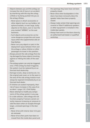 133
133 134
134 135
135 136
136 137
137 138
138 139
139 140
140 141
141 142
142 143
143 144
144 145
145 146
146 147
147 148
148 149
149 150
150 151
151 152
152 153
153 154
154 155
155 156
156 157
157 158
158 159
159 160
160 161
161 162
162 163
163 164
164 165
165 166
166 167
167 168
168 169
169 170
170 171
171 172
172 173
173 174
174 175
175 176
176 177
177 178
178 179
179 180
180 181
181 182
182 183
183 184
184 185
185 186
186 187
187 188
188 189
189 190
190 191
191 192
192 193
193 194
194 195
195 196
196 197
197 198
198 199
199 200
200 201
201 202
202 203
203 204
204 205
205 206
206 207
207 208
208 209
209 210
210 211
211 212
212 213
213 214
214 215
215 216
216 217
217 218
218 219
219 220
220 221
221 222
222 223
223 224
224 225
225 226
226 227
227 228
228 229
229 230
230 231
231 232
232 233
233 234
234 235
235 236
236 237
237 238
238 239
239 240
240 241
241 242
242 243
243