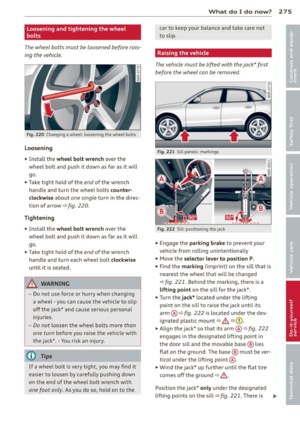
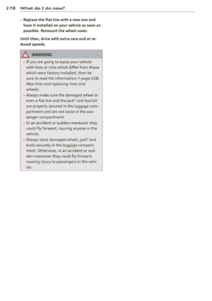
Page 105 of 316

Hybrid 103
Driving situa- Conditions Vehicle behavior
tions
- Do not run the combustion en- The temperature of the comb ust ion eng ine
gine wh ile the vehicle is parked to rises very slowly and the fuel consumption
warm t he engine . increases considerably.
- Use the rear w indow/exterior This conserves the energy in the h igh vo lt-
Driv ing in cold mirro
r defroster and the seat heat- age battery so that it is ava ilab le to run the
weather i
ng sparingly. vehicl e in elect ric mode .
- Park the vehicle in a ga rage over-
This reduces exposure of the hig h voltage
night.
Energy flow display
Applies to vehicles: with hybrid drive
Fig. 10 9 Instrument cluster: e nergy flow disp lay
The energy flow of the hybrid system is shown
i n the instrument cluster display and in the
M MI disp lay. The image is animated in the
MMI display.
Image in the instrument cluster display
.,. Press the !RESET I button in the w indshield
wipe r lever repeated ly until the e ne rgy flow
display
c::> fig . 109 appears .
Component Color
@Combustion engine orange
gray
@ Props haft green
orange
green-o range
g ray battery to co
ld temperatures . The required
temperature range for the hig h voltage
battery will then be reached more quick ly
after you start driving.
Fi g. 1 10 MMI d isp lay: energy flow display
Image in the MMI display
.,. Sele ct: i ME NUI fu nct ion button> Hybrid
contro l button r=;, fig . 110.
Meaning
The combustio n engine is runni ng
The combust io n engine is off
Electric driving/ recuperating
D riving w ith th e combust io n engine
Driving with the combustio n engine and electric
motor (boost)
Vehi cle s ta ti onary/rolling in the N sele ctor lever
p osition
Page 106 of 316

104 Hybrid
Component Color
® High voltage battery green
green (animated
in MMI)
gray
(§) Movement arrow g
reen
orange
green-orange
@ Movement arrow green
@ Tips
The Energy flow dis play will not shown in
the MMI display when the reverse gear is engaged, due to safety reasons.
Consumption display
Ap plies to vehicles: with hybri d drive
Fig. 111 MMI display: consumpt io n disp lay
The consumpt ion d isplay shows the average
energy consumption and the recuperation
quantity in 5 minute interva ls.
Calling up th e co nsumpti on displa y
• Se lect : I MENU I function button> Hybrid
control button.
• Turn the cont ro l knob counter-clockw ise.
R esetting the c onsumption displ ay
• Se lect : IM ENU I function button > Hybr id
control button.
• Turn the cont ro l knob to
R es et con sumpt ion
s tati sti cs.
The orange bars show the average consump
tion and the green bars show the recuperation
Meaning
High voltage battery charge level
High voltage battery is charging
Vehicle is not in drive ready mode
E lectric driving
Driving with the combustion engine
Driving w ith the combust ion engine and electric
motor (boost)
Recuperating
quantity. Each bar represents a measured 5
minute interval. The display covers a 60 mi
nute time period.
The bar with the white border on the outer
right shows the current average consumption
or the current recuperation quant ity . After 5
minutes, this bar travels a step to the left and
a new bar appears in the outer r ight.
The filled bars show the values for the current
drive cycle . Once the ignition is switched off
and on again, all of the previous bars a re d is
played as not filled and new filled bars appear
on the right. This is so that the values from
the p revious trips and the current trip can be
compared visually.
Vehicle tool kit and tire repair set
Appl ies to v ehicles: wi th hybrid drive
Fig. 112 Lu ggage compa rtment: vehicle tool bag and
tire repair set
The vehicle tool kit is found under a cover in
the cargo floor Qfig .
112 @. The tire repair
set (Tire Mobility System) is found in the stor
age compartment in the right side trim panel
®· ~
Page 107 of 316

Additional information about the vehicle tool kit may be found under
c::> page 268 and
about the tire repa ir set under
c::> page 2 71 .
(D Tips
The right storage compartment in the lug
gage compartment and its contents must
always be kept in the vehicle. The veh icle
m ust not be operated w ithout the tire re
pa ir set.
Charging the batteries
Applies to vehicles: with hybrid drive
The vehicle is equipped with two 12 volt bat
ter ies and a h igh voltage battery.
If the 12 volt batter ies are dead, they may be
charged with a charger or the vehicle may be
jump started with assistance from another ve
hicle in the same way as a conventional vehi
cle .
The same applies to the high voltage battery
if it is d ischarged . However, in this case, the
charg ing process is accompanied w ith mes
sages in the inst rument cluste r display. The
i gnit ion m ust be switched on and all unneces
sary electric components m ust be turned off.
The connections in the engine compartment
are used for both charging and jump starting
c::> page 244 or c::> page 283.
Vehicle not ready to start. See owner's
manual
This message appears if the high voltage bat
tery charge level is too low. The vehicle can no
l onge r be started with its own power. The
high voltage battery must be charged with a
charger or the vehicle must be jump started
with the aid of another vehicle.
Afte r the connecting the cha rger or jumper ca
b les, the ignition must be turned off for ap
proximately two minutes and then turned on
again. After no more than one m inute, one of
the following indicator lights turns on in the instrument cluster d isp lay. Hybrid 105
II Charging battery. Please wait ...
If
the indicator light turns on and this mes
sage appears, the high voltage battery is
charging or the vehicle is being jump started
with assistance from another vehicle.
If the 12 vo lt batteries are dead, the -
indicator light turns on. The charging proce
dure takes longer in this case because the 12
vo lt batteries are charged first. The procedure
goes faster with the ignition switched off.
Vehicle ready to start.
This message appears if the charging proce
dure was successfu l. The vehicle may be start
ed again.
Battery could not be charged enough to
start vehicle.
This message appears if the charging proce
dure was not successful or it was interrupted.
This may happen if the charger or the battery
in the veh icle that is assist ing is too weak.
If
the vehicle cannot be started, see an author
ized repa ir facility for assistance .
(D Tips
- The charger should deliver a current of at
least
30 A. Otherwise charging the high
voltage battery will take considerably longer. A current between
50 A and 70 A
is ideal.
- The ve hicle that is assist ing should be
somewhat within the same vehicle class
when jump starting a vehicle. A smaller
vehicle's battery may be drained.
- After approximately
30 minutes, the
c harging procedure ends because the ig
nition is automatically turned off.
If you
would like to continue to charge the bat
tery, turn the ignition on again.
Page 108 of 316
106 Hybrid
Vehicle transport
Applies to vehicles: wit h hybri d drive
The following contains information you
should know about transporting your vehicle .
The lithium ion battery (SANYO 72 UF 121
285) installed in your vehicle has passed test
38 .3 in accordance with UN handbook tests
and criteria. The vehicle may be transported
with the battery installed as conventiona l
class 9 haza rdous materials without addition
al off ic ial consent for air and sea transporta
tion (current law !CAO-TI and IMDG -Code
01.01.2012).
Page 109 of 316

Audi adaptive cruise control and braking guard 107
Audi adaptive cruise
control and braking
guard
Introduction
App lies to vehicles: with Audi adaptive cruise control
The adaptive cruise control system assists the
driver by regu lating vehicle speed and helping
to maintain a set distance to the vehicle
ahead, within the limits of the system . If the
system detects a moving vehicle up ahead,
adaptive cruise control can brake and then ac
celerate your vehicle . Th is he lps to make driv
ing more comfortable on long highway
stretches.
The braking guard system can warn you about
an impending collision and initiate braking
maneuvers
c::;, page 113.
Adaptive cruise control and braking guard
have technical limitations that you must
know, so please read this section carefully, un
derstand how the system works and use them properly at all times.
General information
General information
Applies to vehicles: with Audi adaptive cruise control
Fig. 113 Front of the vehicle: Position of radar sensor
The area that contains the radar sensor
c::;, fig. 113 must never be covered by stickers
or other objects or obstructed with dirt, in
sects, snow or ice that will interfere with the
adaptive cruise control system and braking
guard. For information on cleaning, refer to
c::;, page 217. The same applies for any modifi
cations made in the front area . The
function of the adaptive cruise control
system and braking guard is limited under
some cond itions:
- Objects can only be detected when they are
within sensor range
.:!>page 109 , fig. 116.
-The system has a limited ability to detect
objects that are a short distance ahead, off
to the side of your vehicle or moving into
your lane.
- Some kinds of vehicles are hard to detect;
for examp le motorcycles, vehicles with high
ground clearance or overhanging loads may
be detected when it is too late or they may
not be detected at all.
- When driving through curves
c::;, page 108.
-Stationary objects c::;, page 108.
A WARNING
-Always pay attention to traffic when adap-
tive cruise control is switched on and brak ing guard is active. As the dr iver, you are
still respons ible for start ing and for main
tain ing speed and distance to other ob
jects. Braking guard is used to assist you.
The driver must always take action to avoid
a collision. The driver is always responsible
for braking at the correct time.
- Improper use of adaptive cruise control
can caus e collisions, other accidents and
serious personal inj ury .
- Never let the comfort and convenience
that adap tive cruise control and braking
guard offer d istract you from the need to
be alert to traffic conditions and the
need to remain in fullcontrolofyourve
hicle at all times,
- Always remember that the adaptive
cru ise contro l and braking guard have
limits -they will not slow the vehicle
down or maintain the set distance when
you drive towards an obstacle or some
thing on or near the road that is not
moving, such as vehicles stopped in a
traffic jam, a stalled or disabled vehicle.
If registered by the radar sensor, vehicles
or obstacles that are not moving can
trigger a collision warning and if .,.
Page 110 of 316

108 Audi adaptive cruise control and braking guard
confirmed by the video camera, an acute
collision warning.
- For safety reasons, do not use adaptive
cruise control when driving on roads with
many curves, when the road surface is in
poor condition and/or in bad weather
(such as ice, fog, gravel, heavy rain and
hydroplan ing). Using the system under
these conditions could result in a colli
sion.
- Switch adaptive cruise control off tempo
rar ily when driv ing in turning lanes, on
expressway exits or in construc tion
zones. This prevents the vehicle from ac
celerating to the set speed when in these
situations.
- Th e adaptive cruise control system w ill
not brake by itse lf if you put your foot on
the accelerator pedal. Doing so can over
ride the speed and distance regulation.
- When approaching stationary objects
such as stopped traffic, adaptive cruise
control will not respond and braking
guard w ill have limited function.
- The adaptive cr uise control system and
braking guard do not react to people, an
ima ls, objects crossing the road or on
coming objects .
- The function of the radar sensor can be
affected by reflective objects such as
guard rails, the entrance to a tunnel,
heavy rain or ice.
- Never follow a vehicle so closely that you cannot stop your vehicle safely. The
adaptive cruise control cannot slow or
brake the vehicle safely when you follow
ano ther vehicle too closely . Always re
member that the automatic braking
function cannot bring the vehicle to a sudden or emergency stop under these
conditions.
- To prevent unintended operation, always
switch adaptive cruise control off when it
is not being used.
QJ Note
The sensor can be disp laced by impacts o r
damage to the bumper, whee l housing and underbody.
That could affect the adaptive
cruise control system and braking guard. Have yo ur authorized Aud i dea ler or a u
thorized Audi Service Facility check their
function.
In curves
Applies to vehicles: with Audi adaptive cruise contro l
Fig. 114 Examp le: driv ing into a curve
When driving into a curve¢ fig. 114 and out
of a curve, the adaptive cruise control may re
act to a vehicle in the next lane and app ly the
brakes. You can override or prevent the brak
ing by pressing the accelerator pedal briefly.
' Stationary objects
Applies to vehicles: with Aud i adapt ive cru ise contro l
Fig. 115 Example: object changing lanes and station
a ry object
T he adaptive cru ise control system only reacts
to objects that are moving or that the system
has a lready detected as moving. For examp le,
if a vehi cle@ , which has al ready been detect
ed by the adaptive cruise control, turns or
changes lanes and another stationary vehicle
® is located in front of that vehicle, the sys
tem will not react to the stat ionary veh icle.
Page 111 of 316

Audi adaptive cruise control and braking guard 109
Audi adaptive cruise
control
Description
A pp lies to vehicles: with Audi adaptive cruise control
Fig. 116 Detect ion range
What can adaptive cruise control do?
The adaptive cruise control works in conjunc
tion with a radar sensor installed in the front
of the vehicle
¢page 107, fig. 113, which is
subject to designated system limits
¢page 109. Stationary objects are disregard
ed .
On open roads w ith no traffic, adaptive cruise
control works like a regular cruise control sys
tem. The stored speed is maintained. When
approaching a moving vehicle detected up
ahead, the adaptive cruise control system au
tomatically slows down to match that vehi
cle's speed and then maintains the distance
that the driver previously stored. As soon as
the system does not detect a vehicle up ahead, adaptive cruise control accelerates back up to the stored speed.
Which functions can be controlled?
When you switch adaptive cruise control on,
you can set the current speed as the "control speed" ¢
page 109, Switching on and off.
When driving, you can stop cruise control
¢
page 111 or change the speed ¢ page 11 0
at any time.
You can also set the distance to the object
ahead and set the adaptive cruise control driv ing program
¢ page 111.
Switching on and off
Applies to vehicles: wi th Aud i adap tive crui se contro l
Fig. 117 Selector lever: switch ing on/off
Fig. 118 Instrument cluster: adapt ive c ruise control
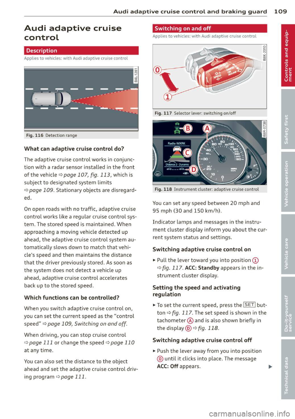
You can set any speed between 20 mph and
95 mph (30 and 150 km/h).
Indicator lamps and messages in the instru
ment cluster display inform you about the cur
rent system status and settings.
Switching adaptive cruise control on
.,. Pull the lever toward you into position (I)
¢fig. 117 . ACC: Standby appears in the in
strument cluster display.
Setting the speed and activating
regulation
.,. To set the current speed, press the ISETI but
ton ¢
fig. 117. The set speed is shown in the
tachometer @and is a lso shown briefly in
the display @¢fig.118.
Switching adaptive cruise control off
.,. Push the lever away from you into position
@ until it clicks into place. The message
ACC: Off appears. ..,.
Page 112 of 316

110 Audi adaptive cruise control and braking guard
@ Indicator lights
r• 1-Adaptive cruise control is switched on . No
vehicles are detected up ahead. The stored
speed is maintained.
I-A moving vehicle is detected up ahead.
The adaptive cruise control system regulates
the speed and distance to the moving vehicle
ahead and accelerates/brakes automatically.
I -When automatic braking is not able to
keep enough distance to a previously detected
moving vehicle up ahead, you must take con
trol and brake<=:>
page 112, Request for driver
intervention.
© Display
If adaptive cruise control is not shown in the
display, you can call it up with the
I RESET !
button ¢ page 20.
Based on the symbols in the display, you can
determine if the system is maintaining a dis
tance to the vehicle ahead and what that dis
tance is.
No vehicle -No vehicle ahead was detected.
White vehicle -A vehicle ahead was detected.
Red vehicle -Prompt for the driver to take ac
tion
<=:> page 112.
Both arrows on the scale © indicate the dis
tance to the vehicle ahead. No arrow appears
when the vehicle is on an open road and there
is no object ahead. If an object is detected
ahead, the arrow moves on the scale.
The green zone on the scale shows the stored
distance. For information on changing the
stored distance, refer to <=:>
page 111. If the
distance selected is too close or may soon be
come too close, the arrows move into the red
zone on the scale .
A WARNING
Improper use of the adaptive cruise con
trol can cause collisions, other accidents
and serious personal injuries.
- Pressing the
ISETI button when driving at
speeds below 20 mph (30 km/h), will au- tomatically accelerate the vehicle to
20 mph (30 km/h), which is the mini
mum speed that can be set.
(D Tips
- If you switch the ignition or the adaptive
cruise control off, the set speed is erased
from the system memory.
- The Electronic Stabilization Control (ESC)
is automatically turned on when the
adaptive cruise control is turned on. You
cannot switch the ESC into offroad mode
while the adaptive cruise control is
turned on
<=:> page 198 .
Changing the speed
Applies to veh icles: w ith Audi adaptive cruise co ntro l
0
f
• 0
Fig. 119 Selector lever: ch an gin g the speed
.,. To increase or reduce the speed in incre
ments,
tap the lever up or down .
.,. To increase or reduce the speed quickly,
hold
the lever up or down until the red LED@
reaches the desired speed <=:>
page 109,
fig . 118.
Following any changes, the new stored speed
will be displayed briefly in the display @
<=:>page 109, fig . 118.