Page 57 of 98

PERIODIC MAINTENANCE AND ADJUSTMENT
6-14
2
3
4
567
8
9
into the radiator until it is full.
7. Install the radiator cap, start the engine, let it idle for several min-
utes, and then turn it off.
8. Remove the radiator cap to check the coolant level in the radiator. If
necessary, add sufficient coolant
until it reaches the bottom of the
radiator filler neck, and then install
the radiator cap.
9. Start the engine, and then check the vehicle for coolant leakage. If
coolant is leaking, have a Yamaha
dealer check the cooling system.
EAU52932
Cleaning the air filter element
and check hose The air filter element should be cleaned
or replaced at the intervals specified in
the periodic maintenance and lubrica-
tion chart. Clean or, if necessary, re-
place the air filter element more
frequently if you are riding in unusually
wet or dusty areas. In addition, the air
filter check hose must be frequently
checked and cleaned if necessary.
To clean the air filter element1. Open the air filter case cover by loosen the quick fastener screw
and pulling the case cover outward
as shown. 2. Unhook the holding clip, and then
pull the air filter element out.
3. Remove the sponge material from the air filter element frame, clean it
Antifreeze/water mixture ratio:1:1
Recommended antifreeze:
High-quality ethylene glycol anti-
freeze containing corrosion inhibitors
for aluminum engines
Coolant quantity: Radiator capacity (including all
routes): 1.04 L (1.10 US qt, 0.92 Imp.qt)
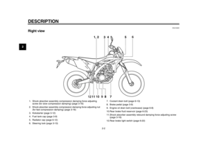
1. Quick fastener screw
2. Air filter case cover
1. Holding clip
2. Air filter element
12
1 2
1DX-9-E1.book 14 ページ 2012年7月31日 火曜日 午前9時31分
Page 58 of 98

PERIODIC MAINTENANCE AND ADJUSTMENT
6-15
1
2
3
4
56
7
8
9with solvent, and then squeeze the
remaining solvent out.
WARNING!
Use only a dedicated parts
cleaning solvent. To avoid the
risk of fire or explosion, do not
use gasoline or solvents with a
low flash point.
[EWA10431]
NOTICE:
To avoid damaging the foam
material, handle it gently and
carefully, and do not twist or
wring it.
[ECA10511]
4. Apply oil of the recommended type
to the entire surface of the sponge
material, and then squeeze the ex-
cess oil out.
TIPThe sponge material should be wet butnot dripping.
5. Pull the sponge material over the air filter element frame.TIP
Align the projection on the air filter
element frame with the hole in the
sponge material.
Apply the lithium soap base grease on the matching surface on
the sponge material.
6. Insert the air filter element into the air filter case. NOTICE: Make sure
that the air filter element is prop-
erly seated in the air filter case.
The engine should never be op-
erated without the air filter ele-
ment installed, otherwise the
piston(s) and/or cylinder(s) may
become excessively worn.
[ECA10481]
TIPAlign the projection on the air filter ele-ment with the hole in the air filter case.
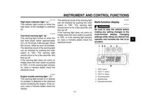
1. Air filter element frame
2. Sponge material
1 2
Recommended oil:
Yamaha foam air filter oil or other
quality foam air filter oil
1. Projection
2. Hole
3. Matching surface
1 23
1DX-9-E1.book 15 ページ 2012年7月31日 火曜日 午前9時31分
Page 59 of 98
PERIODIC MAINTENANCE AND ADJUSTMENT
6-16
2
3
4
567
8
9
7. Place the holding clip in the origi-
nal position.
TIPHook the holding clip so that it contactsthe filter guide projections. 8. Close the air filter case cover, and
then tighten the quick fastener
screw.
To clean the air filter check hose 1. Check the hose at the bottom of the air filter case for accumulated
dirt or water. 2. If dirt or water is visible, remove
the hose, clean it, and then install
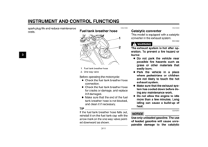
it.1. Hole
2. Projection
3. Air filter element
1 2
3
1. Holding clip
2. Projection
1
2
1. Air filter check hose
1
1DX-9-E1.book 16 ページ 2012年7月31日 火曜日 午前9時31分
Page 60 of 98

PERIODIC MAINTENANCE AND ADJUSTMENT
6-17
1
2
3
4
56
7
8
9
EAU52460
Adjusting the engine idling
speed The engine idling speed must be
checked and, if necessary, adjusted as
follows.TIPA digital tachometer is needed to makethis adjustment.1. Position the digital tachometer at the ignition coil, which is located in
the spark plug cap.
2. Check the engine idling speed and, if necessary, adjust it to spec-
ification by turning the starter
knob/idle adjusting screw. To in-
crease the engine idling speed,
turn the screw in direction (a). To
decrease the engine idling speed,
turn the screw in direction (b).
TIPIf the specified idling speed cannot be
obtained as described above, have aYamaha dealer make the adjustment.
EAU21384
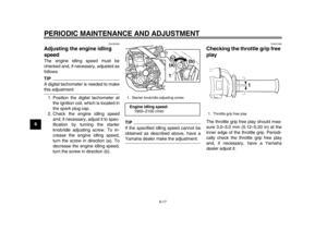
Checking the throttle grip free
play The throttle grip free play should mea-
sure 3.0–5.0 mm (0.12–0.20 in) at the
inner edge of the throttle grip. Periodi-
cally check the throttle grip free play
and, if necessary, have a Yamaha
dealer adjust it.
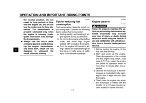
1. Starter knob/idle adjusting screwEngine idling speed:1900–2100 r/min
1(a)
(b)
1. Throttle grip free play
1
1DX-9-E1.book 17 ページ 2012年7月31日 火曜日 午前9時31分
Page 61 of 98

PERIODIC MAINTENANCE AND ADJUSTMENT
6-18
2
3
4
567
8
9
EAU21401
Valve clearance The valve clearance changes with use,
resulting in improper air-fuel mixture
and/or engine noise. To prevent this
from occurring, the valve clearance
must be adjusted by a Yamaha dealer
at the intervals specified in the periodic
maintenance and lubrication chart.
EAU52881
Tires Tires are the only contact between the
vehicle and the road. Safety in all con-
ditions of riding depends on a relatively
small area of road contact. Therefore, it
is essential to maintain the tires in good
condition at all times and replace them
at the appropriate time with the speci-
fied tires.
Tire air pressure
The tire air pressure should be checked
and, if necessary, adjusted before each
ride.
WARNING
EWA10441
Operation of this vehicle with im-
proper tire pressure may cause se-
vere injury or death from loss of
control.
The tire air pressure must be
checked and adjusted on cold
tires (i.e., when the temperature
of the tires equals the ambient
temperature).
The tire air pressure must be ad-
justed in accordance with the
riding speed and with the totalweight of rider, cargo, and ac-
cessories approved for this
model.WARNING
EWA10511
Never overload your vehicle. Opera-
tion of an overloaded vehicle couldcause an accident.
Tire air pressure (measured on cold
tires):
0–90 kg (0–198 lb):Front: 150 kPa (1.50 kgf/cm
2, 22 psi)
Rear: 200 kPa (2.00 kgf/cm2, 29 psi)
Maximum load*:
90 kg (198 lb)
* Total weight of rider, cargo and ac- cessories
1DX-9-E1.book 18 ページ 2012年7月31日 火曜日 午前9時31分
Page 62 of 98

PERIODIC MAINTENANCE AND ADJUSTMENT
6-19
1
2
3
4
56
7
8
9Tire inspection
The tires must be checked before each
ride. If the center tread depth reaches
the specified limit, if the tire has a nail or
glass fragments in it, or if the sidewall is
cracked, have a Yamaha dealer re-
place the tire immediately.
TIPThe tire tread depth limits may differ
from country to country. Always complywith the local regulations. Tire information
This motorcycle is equipped with spoke
wheels and tube tires.
Tires age, even if they have not been
used or have only been used occasion-
ally. Cracking of the tread and sidewall
rubber, sometimes accompanied by
carcass deformation, is an evidence of
ageing. Old and aged tires shall be
checked by tire specialists to ascertain
their suitability for further use.
WARNING
EWA10461
The front and rear tires should be of
the same make and design, other-
wise the handling characteristics of
the vehicle may be different, whichcould lead to an accident.
After extensive tests, only the tires list-
ed below have been approved for this
model by Yamaha Motor Co., Ltd.
WARNING
EWA10571
Have a Yamaha dealer replace
excessively worn tires. Besides
being illegal, operating the mo-
torcycle with excessively worn
tires decreases riding stability
and can lead to loss of control.
The replacement of all wheel-
and brake-related parts, includ-
ing the tires, should be left to a
Yamaha dealer, who has the
necessary professional knowl-
edge and experience.
It is not recommended to patch
a punctured tube. If unavoid-
able, however, patch the tube
very carefully and replace it as
soon as possible with a
1. Tire sidewall
2. Tire tread depthMinimum tire tread depth (front and
rear):
1.6 mm (0.06 in)
Front tire: Size:80/100-21M/C 51P
Manufacturer/model:
BRIDGESTONE/GRITTY-ED03 E
Rear tire: Size:
120/90-18M/C 65P
Manufacturer/model: BRIDGESTONE/GRITTY-ED04 E
1DX-9-E1.book 19 ページ 2012年7月31日 火曜日 午前9時31分
Page 63 of 98

PERIODIC MAINTENANCE AND ADJUSTMENT
6-20
2
3
4
567
8
9
high-quality product.
Ride at moderate speeds after
changing a tire since the tire
surface must first be “broken
in” for it to develop its optimalcharacteristics.
EAU21943
Spoke wheels
WARNING
EWA10610
The wheels on this model are not de-
signed for use with tubeless tires.
Do not attempt to use tubeless tireson this model.
To maximize the performance, durabil-
ity, and safe operation of your motorcy-
cle, note the following points regarding
the specified wheels.
The wheel rims should be checked
for cracks, bends, warpage or oth-
er damage, and the spokes for
looseness or damage before each
ride. If any damage is found, have
a Yamaha dealer replace the
wheel. Do not attempt even the
smallest repair to the wheel. A de-
formed or cracked wheel must be
replaced.
The wheel should be balanced
whenever either the tire or wheel
has been changed or replaced. An
unbalanced wheel can result in
poor performance, adverse han-
dling characteristics, and a short-
ened tire life.
EAU52911
Adjusting the cl
utch lever free
play The clutch lever free play should mea-
sure 8.0–13.0 mm (0.31–0.51 in) as
shown. Periodically check the clutch le-
ver free play and, if necessary, adjust it
as follows.
1. To increase the clutch lever free play, turn the clutch lever free play
adjusting bolt in direction (a). To
decrease the clutch lever free play,
turn the adjusting bolt in direction
(b).TIPIf the specified clutch lever free play1. Clutch lever free play
2. Clutch lever free play adjusting bolt1
(a)
(b)
2
1DX-9-E1.book 20 ページ 2012年7月31日 火曜日 午前9時31分
Page 64 of 98
 to loosen the clutch ca-
ble.
3. Sl")
PERIODIC MAINTENANCE AND ADJUSTMENT
6-21
1
2
3
4
56
7
8
9could be obtained as described above,
skip steps 2–5.
2. Fully turn the adjusting bolt in di- rection (a) to loosen the clutch ca-
ble.
3. Slide the rubber cover back further down the clutch cable, and then
loosen the locknut.
4. To increase the clutch lever free play, turn the clutch lever free play
adjusting nut in direction (a). To
decrease the clutch lever free play,
turn the adjusting nut in direction
(b). 5. Tighten the locknut at the clutch
cable, and then slide the rubber
cover to its original position.
EAU37913
Checking the brake lever free
play There should be no free play at the
brake lever end. If there is free play,
have a Yamaha dealer inspect the
brake system.
WARNING
EWA14211
A soft or spongy feeling in the brake
lever can indicate the presence of air
in the hydraulic system. If there is air
in the hydraulic system, have a
Yamaha dealer bleed the system be-
fore operating the vehicle. Air in the
hydraulic system will diminish the
braking performance, which may re-
1. Locknut
2. Clutch lever free play adjusting nut (clutch
cable)
3. Rubber cover
1
2 (a)
(b)
3
1. No brake lever free play
1
1DX-9-E1.book 21 ページ 2012年7月31日 火曜日 午前9時31分