Page 17 of 98

INSTRUMENT AND CONTROL FUNCTIONS
3-2
234
5
6
7
8
9
EAU11080
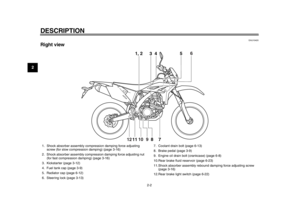
High beam indicator light “ ”
This indicator light comes on when the
high beam of the headlight is switched
on.
EAU52390
Fuel level warning light “ ”
This warning light comes on when the
fuel level drops below approximately
3.0 L (0.79 US gal, 0.66 Imp.gal). When
this occurs, refuel as soon as possible.
The electrical circuit of the warning light
can be checked by pushing the main
switch to “ON”. The warning light
should come on for a few seconds, and
then go off.
If the warning light does not come on
initially when the main switch is pushed
to “ON”, or if the warning light remains
on, have a Yamaha dealer check the
electrical circuit.
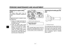
EAU52400
Engine trouble warning light “ ”
This warning light comes on or flashes
if a problem is detected in the electrical
circuit monitoring the engine. If this oc-
curs, have a Yamaha dealer check the
vehicle. The electrical circuit of the warning light
can be checked by pushing the main
switch to “ON”. The warning light
should come on for a few seconds, and
then go off.
If the warning light does not come on
initially when the main switch is pushed
to “ON”, or if the warning light remains
on, have a Yamaha dealer check the
electrical circuit.
EAU52922
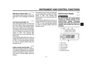
Multi-function display
WARNING
EWA12312
Be sure to stop the vehicle before
making any setting changes to the
multi-function display. Changing
settings while riding can distract the
operator and increase the risk of anaccident.1. “RST” button
2. “SLCT 1” button
3. “SLCT 2” button
4. Clock/stopwatch
5. Speedometer
6. Odometer/tripmeter
123
4
6
5
1DX-9-E1.book 2 ページ 2012年7月31日 火曜日 午前9時31分
Page 18 of 98

INSTRUMENT AND CONTROL FUNCTIONS
3-3
1
23
4
5
6
7
8
9
TIP
The multi-function display can be
set to the basic mode or the mea-
surement mode.
Tripmeter A will automatically re-
set to zero when changing from
the basic mode to the measure-ment mode or vice versa.
Basic mode:
a speedometer
an odometer
two tripmeters (which show the
distance traveled since they were last set to zero)
a clock
Measurement mode:
a speedometer
a distance-compensation tripme-
ter (which shows the accumulated
distance traveled since set to zero
and which can be calibrated to pro-
vide a more accurate tripmeter
reading)
a stopwatch (which shows the time
that has been accumulated since
the start of stopwatch measure-
ment)
TIP
Be sure to push the main switch to
“ON” before using the “SLCT 1”,
“SLCT 2” and “RST” buttons.
When the main switch is pushed to
“ON”, all of the display segments
of the multi-function display will ap-
pear and then disappear, in order
to test the electrical circuit.
For the U.K. only: To switch the
speedometer and odometer/trip-
meter displays between kilometers
and miles, press the “SLCT 2” but- ton until the display changes after
the main switch is pushed to “ON”.
Basic mode
Odometer and tripmeter modes
Push the “SLCT 2” button to switch the
display between the odometer mode
and the tripmeter modes A and B in the
following order:
odometer tripmeter A tripmeter B
odometer
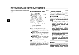
1. Stopwatch indicator “ ”
2. Tripmeter A indicator “ ”/Distance-com-
pensation tripmeter “ ”
3. Tripmeter B indicator “ ”
12
3
1. Tripmeter A indicator “ ”
1
1DX-9-E1.book 3 ページ 2012年7月31日 火曜日 午前9時31分
Page 19 of 98

INSTRUMENT AND CONTROL FUNCTIONS
3-4
234
5
6
7
8
9
TIPIndicator “ ” comes on when tripmeter
A is selected, and indicator “ ” comeson when tripmeter B is selected.
To reset a tripmeter, select it by push-
ing the “SLCT 2” button, and then push
the “RST” button for at least one sec-
ond.
ClockThe clock displays when the main
switch is pushed to “ON”.
To set the clock1. Push the “SLCT 1” button for atleast two seconds.
2. When the hour digits start flashing, push either select button to set the
hours.
3. Push the “RST” button, and the minute digits will start flashing.
4. Push either select button to set the minutes.
5. Push the “RST” button, and the second digits will start flashing.
6. Push either select button to set the second digits to zero.
7. Push the “RST” button for at least two seconds, and then release it to
start the clock.
TIP
When setting the clock, push the
“SLCT 1” button to increase the
digits or “SLCT 2” button to de-
crease the digits. Pushing and
holding either button will increase
or decrease the digits continuously
until the button is released.
If a button is not pushed within 30
seconds while setting the clock,
the clock will be set to the currentlydisplayed time. Changing from the basic mode to
the measurement mode
With the odometer selected, push the
“SLCT 1” button and “SLCT 2” button
together for at least two seconds to
change to the measurement mode.
Changing from the measurement
mode to the basic mode
TIPThe stopwatch must be stopped beforechanging to the basic mode.
1. Check that the stopwatch is not in operation. If the stopwatch is in op-
eration, stop it by pushing the
“SLCT 1” button and “SLCT 2” but-
ton together.
2. Push the “SLCT 1” button and “SLCT 2” button together for at
least two seconds to change to the
basic mode.
Measurement mode (for the stop-
watch)
When the measurement mode is se-
lected, the stopwatch is displayed and it
can be started manually or automatical-
ly.
1. Tripmeter B indicator “ ”
1
1DX-9-E1.book 4 ページ 2012年7月31日 火曜日 午前9時31分
Page 20 of 98

INSTRUMENT AND CONTROL FUNCTIONS
3-5
1
23
4
5
6
7
8
9
TIPStarting measurement consists of the
following two starts, either of which can
be selected.
Manual start
Starting measurement by the rider
himself operating the button. (A
long push on the “SLCT 2” button
will put measurement on standby.)
Auto start
Starting timer measurement auto-
matically on detection of the move-
ment of the machine. (A long push
on the “SLCT 1” button will putmeasurement on standby.)
Manual start
The manual start is the default setting
for the stopwatch. The stopwatch indi-
cator “ ” and the distance-compensa-
tion tripmeter indicator “ ” will start
flashing. 1. Push the “RST” button to start the
stopwatch.
2. Push the “SLCT 1” button and “SLCT 2” button together to stop
the stopwatch.
3. To resume stopwatch counting, push the “SLCT 1” button and
“SLCT 2” button together.
To reset the stopwatch to zero,
push the “RST” button for at least
two seconds.
TIPThe stopwatch will continue counting
when the vehicle is stopped. To stop
and/or resume counting, repeat steps 2and 3. Auto start
1. Push the “SLCT 1” button for at
least two seconds to set the auto
start.TIPWhen the stopwatch is set to auto start,
the stopwatch indicator “ ” and the
distance-compensation tripmeter indi-
cator “ ” will start flashing, and the dig-
its in the display will start scrolling fromleft to right.
2. When the vehicle starts moving, the stopwatch will start counting.
3. Push the “SLCT 1” button and “SLCT 2” button together to stop
the stopwatch.
4. To resume counting, push the “SLCT 1” button and “SLCT 2” but-
1DX-9-E1.book 5 ページ 2012年7月31日 火曜日 午前9時31分
Page 21 of 98

INSTRUMENT AND CONTROL FUNCTIONS
3-6
234
5
6
7
8
9
ton together again.
TIPThe stopwatch will continue counting
when the vehicle is stopped. To stop
and/or resume counting, repeat steps 3and 4.
Measurement mode (for calibrating
the distance-compensation tripme-
ter’s reading)
The distance-compensation tripmeter
is a feature intended to provide a more
accurate tripmeter reading for enduro
riding. Calibrating this meter in accor-
dance with the distances specified on
the enduro course map will help famil-
iarize the rider with the course. In addi-
tion, calibrating the meter may also be
necessary when using tire, wheel,
chain sprocket sizes, etc. other than
specified. For further information con-
cerning the use of this meter, please
consult your nearby Yamaha dealer.
Calibrate the distance-compensation
tripmeter as follows.
To increase the reading, push the
“SLCT 1” button. To decrease the read-
ing, push the “SLCT 2” button. Pushing and holding either button will increase
or decrease the reading continuously
until the button is released.
TIPCalibrating the reading of the dis-
tance-compensation tripmeter is possi-
ble regardless of the stopwatchoperation.
Resetting the distance-compensa-
tion tripmeter or the distance-com-
pensation tripmeter in combination
with the stopwatchTIPResetting can be made only to the dis-
tance-compensation tripmeter or to the
distance-compensation tripmeter incombination with the stopwatch.
Resetting the distance-compensationtripmeter1. Check that the stopwatch mea-
surement is in operation.
2. Reset the distance-compensation tripmeter to zero by pushing the
“RST” button for at least two sec-
onds. Resetting the distance-compensation
tripmeter in combination with the stop-watch1. Stop the stopwatch.
2. Reset the distance-compensation
tripmeter and the stopwatch to
zero by pushing the “RST” button
for at least two seconds.
1DX-9-E1.book 6 ページ 2012年7月31日 火曜日 午前9時31分
Page 22 of 98

INSTRUMENT AND CONTROL FUNCTIONS
3-7
1
23
4
5
6
7
8
9
EAU1234B
Handlebar switches Left
Right
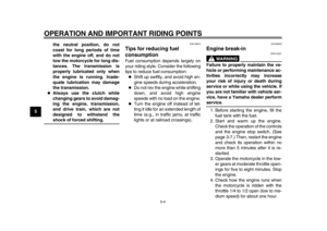
EAU12400
Dimmer switch “ / ”
Set this switch to “ ” for the high
beam and to “ ” for the low beam.
EAU12460
Turn signal switch “ / ”
To signal a right-hand turn, push this
switch to “ ”. To signal a left-hand
turn, push this switch to “ ”. When re-
leased, the switch returns to the center
position. To cancel the turn signal
lights, push the switch in after it has re-
turned to the center position.
EAU12500
Horn switch “ ”
Press this switch to sound the horn.
EAU12660
Engine stop switch “ / ”
Set this switch to “ ” before starting
the engine. Set this switch to “ ” to
stop the engine in case of an emergen-
cy, such as when the vehicle overturns
or when the throttle cable is stuck.
EAU12711
Start switch “ ”
Push this switch to crank the enginewith the starter. See page 5-1 for start-
ing instructions prior to starting the en-
gine.
EAU52440
The engine trouble warning light will
come on when the main switch is
pushed to “ON” and the start switch is
pushed, but this does not indicate a
malfunction.
1. Dimmer switch “ / ”
2. Turn signal switch “ / ”
3. Horn switch “ ”
1. Engine stop switch “ / ”
2. Start switch “ ”
1
2
31
2
1DX-9-E1.book 7 ページ 2012年7月31日 火曜日 午前9時31分
Page 23 of 98

INSTRUMENT AND CONTROL FUNCTIONS
3-8
234
5
6
7
8
9
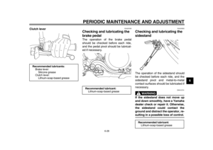
EAU12820
Clutch lever The clutch lever is located at the left
handlebar grip. To disengage the
clutch, pull the lever toward the handle-
bar grip. To engage the clutch, release
the lever. The lever should be pulled
rapidly and released slowly for smooth
clutch operation.
The clutch lever is equipped with a
clutch switch, which is part of the igni-
tion circuit cut-off system. (See
page 3-19.)
EAU12871
Shift pedal The shift pedal is located on the left
side of the motorcycle and is used in
combination with the clutch lever when
shifting the gears of the 5-speed con-
stant-mesh transmission equipped on
this motorcycle.
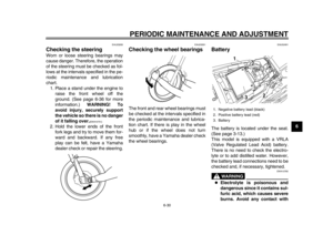
EAU41264
Brake lever The brake lever is located on the right
side of the handlebar. To apply the front
brake, pull the lever toward the throttle
grip.
The brake lever is equipped with a
brake lever position adjusting bolt. Ad-
just the distance between the brake le-
ver and the throttle grip as follows.1. Slide the rubber cover toward the end of the brake lever.
2. Loosen the locknut.
1. Clutch lever
1
1. Shift pedal
1
1. Rubber cover
2. Brake lever
3. Distance between brake lever and throttle grip
4. Locknut
5. Brake lever position adjusting bolt
1
2
3
4
5
(b)
(a)
1DX-9-E1.book 8 ページ 2012年7月31日 火曜日 午前9時31分
Page 24 of 98
INSTRUMENT AND CONTROL FUNCTIONS
3-9
1
23
4
5
6
7
8
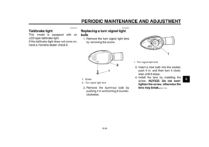
93. While holding the lever pushed
away from the throttle grip, turn the
adjusting bolt in direction (a) to in-
crease the distance, and in direc-
tion (b) to decrease it.
4. Tighten the locknut.
5. Slide the rubber cover to its origi- nal position.
EAU12941
Brake pedal The brake pedal is on the right side of
the motorcycle. To apply the rear
brake, press down on the brake pedal.
EAU13182
Fuel tank cap To remove the fuel tank cap, turn it
counterclockwise, and then pull it off.
To install the fuel tank cap, insert it into
the tank opening, and then turn it clock-
wise.
WARNING
EWA11091
Make sure that the fuel tank cap is
properly closed after filling fuel.Leaking fuel is a fire hazard.
Distance between the brake lever
and the throttle grip:Minimum (shortest):
76 mm (2.99 in)
Standard: 95 mm (3.74 in)
Maximum (longest): 97 mm (3.82 in)
1. Brake pedal
1
1. Fuel tank cap
1
1DX-9-E1.book 9 ページ 2012年7月31日 火曜日 午前9時31分


 to in-
crease the distance, and in direc-
t")