Page 25 of 98

INSTRUMENT AND CONTROL FUNCTIONS
3-10
234
5
6
7
8
9
EAU13212
Fuel Make sure there is sufficient gasoline in
the tank.
WARNING
EWA10881
Gasoline and gasoline vapors are
extremely flammable. To avoid fires
and explosions and to reduce the
risk of injury when refueling, followthese instructions.1. Before refueling, turn off the en- gine and be sure that no one is sit-
ting on the vehicle. Never refuel
while smoking, or while in the vi-
cinity of sparks, open flames, or
other sources of ignition such as
the pilot lights of water heaters and
clothes dryers.
2. Do not overfill the fuel tank. Stop filling when the fuel reaches the
bottom of the filler tube. Because
fuel expands when it heats up,
heat from the engine or the sun
can cause fuel to spill out of the
fuel tank. 3. Wipe up any spilled fuel immedi-
ately. NOTICE: Immediately wipe
off spilled fuel with a clean, dry,
soft cloth, since fuel may deteri-
orate painted surfaces or plastic
parts.
[ECA10071]
4. Be sure to securely close the fuel tank cap.
WARNING
EWA15151
Gasoline is poisonous and can
cause injury or death. Handle gaso-
line with care. Never siphon gaso-
line by mouth. If you should swallow
some gasoline or inhale a lot of gas-
oline vapor, or get some gasoline in your eyes, see your doctor immedi-
ately. If gasoline spills on your skin,
wash with soap and water. If gaso-
line spills on your clothing, change
your clothes.
EAU13391
NOTICE
ECA11400
Use only unleaded gasoline. The use
of leaded gasoline will cause severe
damage to internal engine parts,
such as the valves and piston rings,as well as to the exhaust system.
Your Yamaha engine has been de-
signed to use premium unleaded gaso-
line with a research octane number of
95 or higher. If knocking (or pinging) oc-
curs, use a gasoline of a different
brand. Use of unleaded fuel will extend
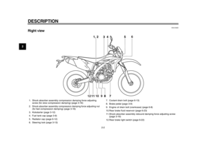
1. Fuel tank filler tube
2. Maximum fuel level
21
Recommended fuel:
Premium unleaded gasoline only
Fuel tank capacity:
7.2 L (1.90 US gal, 1.58 Imp.gal)
Fuel reserve amount (when the fuel
level warning light comes on): 3.0 L (0.79 US gal, 0.66 Imp.gal)
1DX-9-E1.book 10 ページ 2012年7月31日 火曜日 午前9時31分
Page 26 of 98

INSTRUMENT AND CONTROL FUNCTIONS
3-11
1
23
4
5
6
7
8
9spark plug life and reduce maintenance
costs.
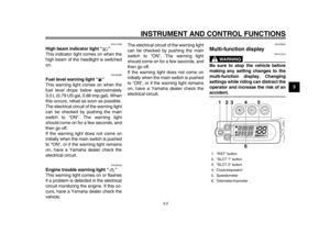
EAU41360
Fuel tank breather hose Before operating the motorcycle:
Check the fuel tank breather hose
connection.
Check the fuel tank breather hose
for cracks or damage, and replace
it if damaged.
Make sure that the end of the fuel
tank breather hose is not blocked,
and clean it if necessary.
TIPIf the fuel tank breather hose falls out,
reinstall it on the fuel tank cap with the
arrow mark on the one-way valve point-ed downward as shown.
EAU13433
Catalytic converter This model is equipped with a catalytic
converter in the exhaust system.
WARNING
EWA10862
The exhaust system is hot after op-
eration. To prevent a fire hazard or
burns:
Do not park the vehicle near
possible fire hazards such as
grass or other materials that
easily burn.
Park the vehicle in a place
where pedestrians or children
are not likely to touch the hot
exhaust system.
Make sure that the exhaust sys-
tem has cooled down before do-
ing any maintenance work.
Do not allow the engine to idle
more than a few minutes. Long
idling can cause a build-up ofheat.
NOTICE
ECA10701
Use only unleaded gasoline. The use
of leaded gasoline will cause unre-
pairable damage to the catalytic
1. Fuel tank breather hose
2. One-way valve
21
1DX-9-E1.book 11 ページ 2012年7月31日 火曜日 午前9時31分
Page 27 of 98
INSTRUMENT AND CONTROL FUNCTIONS
3-12
234
5
6
7
8
9
converter.
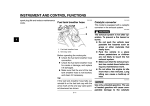
EAU53230
Starter knob Starting a cold engine requires a richer
air-fuel mixture, which is supplied by
the starter.
Move the knob in direction (a) to turn on
the starter.
Move the knob in direction (b) to turn off
the starter.
EAU13650
Kickstarter To start the engine, fold out the kick-
starter lever, move it down lightly with
your foot until the gears engage, and
then push it down smoothly but force-
fully. This model is equipped with a pri-
mary kickstarter, allowing the engine to
be started in any gear if the clutch is
disengaged. However, shifting the
transmission into the neutral position
before starting is recommended.
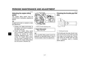
1. Starter knob/idle adjusting screw
(a)
(b)1
1. Kickstarter lever1
1DX-9-E1.book 12 ページ 2012年7月31日 火曜日 午前9時31分
Page 28 of 98
INSTRUMENT AND CONTROL FUNCTIONS
3-13
1
23
4
5
6
7
8
9
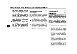
EAU53100
Steering lock To lock the steering1. Turn the handlebar all the way to the left.
2. Insert the key into the steering lock under the steering head pipe, and
then turn it 1/2 turn in either direc-
tion.
3. Check that the steering is locked, and then remove the key from the
lock.
To unlock the steering 1. Insert the key into the steering lock.
2. Turn the key 1/2 turn in either di- rection.
3. Remove the key. WARNING!
Never ride with the key inserted
into the steering lock, which
may result in loss of control and
an accident.
[EWA16160]
EAU53200
Seat To remove the seat
Remove the bolts, and then slide the
seat to the rear and pull upward.
1. Steering lock
1
1. Bolt
1. Bolt
11
1DX-9-E1.book 13 ページ 2012年7月31日 火曜日 午前9時31分
Page 29 of 98

INSTRUMENT AND CONTROL FUNCTIONS
3-14
234
5
6
7
8
9
To install the seat
1. Fit the slot in the seat onto the pro- jection on the fuel tank.
2. Place the seat in the original posi- tion, and then tighten the bolts.
TIPMake sure that the seat is properly se-cured before riding.
EAU52450
Adjusting the front fork
WARNING
EWA10180
Always adjust both fork legs equal-
ly, otherwise poor handling and lossof stability may result.
This front fork is equipped with rebound
damping force adjusting screws and
compression damping force adjusting
screws.NOTICE
ECA10101
To avoid damaging the mechanism,
do not attempt to turn beyond themaximum or minimum settings.
Rebound damping force
To increase the rebound damping force
and thereby harden the rebound damp-
ing, turn the adjusting screw on each
fork leg in direction (a). To decrease the
rebound damping force and thereby
soften the rebound damping, turn the
adjusting screw on each fork leg in di-
rection (b). Compression damping force
To increase the compression damping
force and thereby harden the compres-
sion damping, turn the adjusting screw
on each fork leg in direction (a). To de-
crease the compression damping force
and thereby soften the compression
damping, turn the adjusting screw on
1. Slot
2. Projection2
1
1. Rebound damping force adjusting screwRebound damping setting:
Minimum (soft):
20 click(s) in direction (b)*
Standard: 12 click(s) in direction (b)*
Maximum (hard): 0 click(s) in direction (b)*
* With the adjusting screw fully turned
in direction (a)
1
(a) (b)
1DX-9-E1.book 14 ページ 2012年7月31日 火曜日 午前9時31分
Page 30 of 98
.
TIPAlthough the total number of clicks of a
damping force adjusting mechanism
may not exactly match the above spec")
INSTRUMENT AND CONTROL FUNCTIONS
3-15
1
23
4
5
6
7
8
9each fork leg in direction (b).
TIPAlthough the total number of clicks of a
damping force adjusting mechanism
may not exactly match the above spec-
ifications due to small differences in
production, the actual number of clicks
always represents the entire adjusting range. To obtain a precise adjustment,
it would be advisable to check the num-
ber of clicks of each damping force ad-
justing mechanism and to modify the
specifications as necessary.
EAU14793
Front fork bleeding
WARNING
EWA10200
Always bleed both fork legs, other-
wise poor handling and loss of sta-bility may result.
When riding in extremely rough condi-
tions, the air temperature and pressure
in the front fork will rise. This will in-
crease the spring preload and harden
the front suspension. If this occurs,
bleed the front fork as follows.
1. Lift the front wheel off the ground according to the procedure on
page 6-36.TIPWhen bleeding the front fork, there
should be no weight on the front end ofthe vehicle.
2. Remove the bleed screws and al- low all of the air to escape from
each fork leg.
1. Compression damping force adjusting screwCompression damping setting:Minimum (soft):
20 click(s) in direction (b)*
Standard: 14 click(s) in direction (b)*
Maximum (hard): 0 click(s) in direction (b)*
* With the adjusting screw fully turned
in direction (a)
(a)(b)
1
1DX-9-E1.book 15 ページ 2012年7月31日 火曜日 午前9時31分
Page 31 of 98

INSTRUMENT AND CONTROL FUNCTIONS
3-16
234
5
6
7
8
9
3. Install the bleed screws.
4. Lower the front wheel so that it is
on the ground, and then put the
sidestand down.
EAU52892
Adjusting the shock absorber
assembly This shock absorber assembly is
equipped with a spring preload adjust-
ing ring, a rebound damping force ad-
justing screw, a compression damping
force adjusting bolt (for fast compres-
sion damping) and a compression
damping force adjusting screw (for
slow compression damping).NOTICE
ECA10101
To avoid damaging the mechanism,
do not attempt to turn beyond themaximum or minimum settings.
Spring preload
Spring preload adjustment should be
made by a Yamaha dealer, since this
service requires special tools and tech-
nical skills. The specified settings are
listed below.
The spring preload setting is deter-
mined by measuring distance A, shown
in the illustration. The shorter the dis-
tance A is, the higher the spring pre-
load; the longer distance A is, the lower the spring preload.
Rebound damping force
To increase the rebound damping force
and thereby harden the rebound damp-
ing, turn the adjusting screw in direction
(a). To decrease the rebound damping
force and thereby soften the rebound
damping, turn the adjusting screw in di-
rection (b).
1. Bleed screw
1
1. Distance ASpring preload:
Minimum (soft):
Distance A = 238.5 mm (9.39 in)
Standard: Distance A = 222 mm (8.74 in)
Maximum (hard): Distance A = 222 mm (8.74 in)
1
1DX-9-E1.book 16 ページ 2012年7月31日 火曜日 午前9時31分
Page 32 of 98
To increase the compression damping
force and thereby harden the")
INSTRUMENT AND CONTROL FUNCTIONS
3-17
1
23
4
5
6
7
8
9Compression damping force
Compression damping force (for fast
compression damping)To increase the compression damping
force and thereby harden the compres-
sion damping, turn the adjusting bolt in
direction (a). To decrease the compres- sion damping force and thereby soften
the compression damping, turn the ad-
justing bolt in direction (b).
Compression damping force (for slow
compression damping)To increase the compression damping
force and thereby harden the compres-sion damping, turn the adjusting screw
in direction (a). To decrease the com-
pression damping force and thereby
soften the compression damping, turn
the adjusting screw in direction (b).
TIPTo obtain a precise adjustment, it is ad-
1. Rebound damping force adjusting screwRebound damping setting:
Minimum (soft):
30 click(s) in direction (b)*
Standard: 18 click(s) in direction (b)*
Maximum (hard): 0 click(s) in direction (b)*
* With the adjusting screw fully turned
in direction (a)
(a)
(b)1
1. Compression damping force adjusting bolt
(for fast compression damping)Compression damping setting (for
fast compression damping):Minimum (soft):2 turn(s) in direction (b)*
Standard:
7/8 turn(s) in direction (b)*
Maximum (hard): 0 turn(s) in direction (b)*
* With the adjusting bolt fully turned in direction (a)
1 (a)
(b)
1. Compression damping force adjusting
screw (for slow compression damping)Compression damping setting (for
slow compression damping):Minimum (soft):20 click(s) in direction (b)*
Standard:
10 click(s) in direction (b)*
Maximum (hard): 0 click(s) in direction (b)*
* With the adjusting screw fully turned
in direction (a)
1 (a)
(b)
1DX-9-E1.book 17 ページ 2012年7月31日 火曜日 午前9時31分