Page 33 of 98

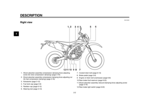
INSTRUMENT AND CONTROL FUNCTIONS
3-18
234
5
6
7
8
9
visable to check the actual total number
of clicks or turns of each damping force
adjusting mechanism. This adjustment
range may not exactly match the spec-
ifications listed due to small differences
in production.
WARNING
EWA10221
This shock absorber assembly con-
tains highly pressurized nitrogen
gas. Read and understand the fol-
lowing information before handling
the shock absorber assembly.
Do not tamper with or attempt to
open the cylinder assembly.
Do not subject the shock ab-
sorber assembly to an open
flame or other high heat source.
This may cause the unit to ex-
plode due to excessive gas
pressure.
Do not deform or damage the
cylinder in any way. Cylinder
damage will result in poor
damping performance.
Do not dispose of a damaged or
worn-out shock absorber as-
sembly yourself. Take the shock absorber assembly to a Yamaha
dealer for any service.
EAU15305
Sidestand The sidestand is located on the left side
of the frame. Raise the sidestand or
lower it with your foot while holding the
vehicle upright.TIPThe built-in sidestand switch is part of
the ignition circuit cut-off system, which
cuts the ignition in certain situations.
(See the following section for an expla-
nation of the ignition circuit cut-off sys-tem.)
WARNING
EWA10241
The vehicle must not be ridden with
the sidestand down, or if the side-
stand cannot be properly moved up
(or does not stay up), otherwise the
sidestand could contact the ground
and distract the operator, resulting
in a possible loss of control.
Yamaha’s ignition circuit cut-off
system has been designed to assist
the operator in fulfilling the respon-
sibility of raising the sidestand be-
fore starting off. Therefore, check
this system regularly and have a
1DX-9-E1.book 18 ページ 2012年7月31日 火曜日 午前9時31分
Page 34 of 98
INSTRUMENT AND CONTROL FUNCTIONS
3-19
1
23
4
5
6
7
8
9Yamaha dealer repair it if it does not
function properly.
EAU52861
Ignition circuit cut-off system The ignition circuit cut-off system (com-
prising the sidestand switch, clutch
switch and neutral switch) has the fol-
lowing functions.
It prevents starting when the trans-
mission is in gear and the side-
stand is up, but the clutch lever is
not pulled.
It prevents starting when the trans-
mission is in gear and the clutch le-
ver is pulled, but the sidestand is
still down.
It cuts the running engine when the
transmission is in gear and the sid-
estand is moved down.
Periodically check the operation of the
ignition circuit cut-off system according
to the following procedure.
1DX-9-E1.book 19 ページ 2012年7月31日 火曜日 午前9時31分
Page 35 of 98

INSTRUMENT AND CONTROL FUNCTIONS
3-20
234
5
6
7
8
9
With the engine turned off:
1. Move the sidestand down.
2. Make sure that the engine stop switch is set to “
3. Push the main switch to “ON”.
4. Shift the transmission into the neutral position.
5. Push the start switch.
Does the engine start?
With the engine still running:
6. Move the sidestand up.
7. Keep the clutch lever pulled.
8. Shift the transmission into gear.
9. Move the sidestand down.
Does the engine stall?
After the engine has stalled:
10. Move the sidestand up.
11. Keep the clutch lever pulled.
12. Push the start switch.
Does the engine start?
The system is OK. The motorcycle can be ridden.The neutral switch may not be working correctly.
The motorcycle should not be ridden until
checked by a Yamaha dealer.
The sidestand switch may not be working correctly.
The motorcycle should not be ridden until
checked by a Yamaha dealer.
The clutch switch may not be working correctly.
The motorcycle should not be ridden until
checked by a Yamaha dealer.
YES NO YES NO YES NO
If a malfunction is noted, have a Yamaha
dealer check the system before riding.
WARNING
”.
1DX-9-E1.book 20 ページ 2012年7月31日 火曜日 午前9時31分
Page 36 of 98

4-1
1
2
34
5
6
7
8
9
FOR YOUR SAFETY – PRE-OPERATION CHECKS
EAU15596
Inspect your vehicle each time you use it to make sure the vehicle is in safe operating condition. Always follow the inspection
and maintenance procedures and schedules described in the Owner’s Manual.
WARNING
EWA11151
Failure to inspect or maintain the vehicle properly increases the possibility of an accident or equipment damage.
Do not operate the vehicle if you find any problem. If a problem cannot be corrected by the procedures provided inthis manual, have the vehicle inspected by a Yamaha dealer.
Before using this vehicle, check the following points:
ITEM CHECKS PAGE
Fuel Check fuel level in fuel tank.
Refuel if necessary.
Check fuel line for leakage.
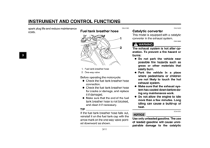
Check fuel tank breather hose for obst
ructions, cracks or damage, and check
hose connection. 3-10, 3-11
Engine oil Check oil level in oil tank.
If necessary, add recommended oil to specified level.
Check vehicle for oil leakage. 6-8
Coolant Check coolant level.
If necessary, add recommended coolant to specified level.
Check cooling system for leakage. 6-12
Front brake Check operation.
If soft or spongy, have Yamaha dealer bleed hydraulic system.
Check brake pads for wear.
Replace if necessary.
Check fluid level in reservoir.
If necessary, add specified brak
e fluid to specified level.
Check hydraulic system for leakage. 6-23
1DX-9-E1.book 1 ページ 2012年7月31日 火曜日 午前9時31分
Page 37 of 98

FOR YOUR SAFETY – PRE-OPERATION CHECKS
4-2
2
345
6
7
8
9
Rear brake Check operation.
If soft or spongy, have Yamaha dealer bleed hydraulic system.
Check brake pads for wear.
Replace if necessary.
Check fluid level in reservoir.
If necessary, add specified brak
e fluid to specified level.
Check hydraulic system for leakage. 6-23
Clutch Check operation.
Lubricate cable if necessary.
Check lever free play.
Adjust if necessary. 6-20
Throttle grip Make sure that operation is smooth.
Check throttle grip free play.
If necessary, have Yamaha dealer adjust
throttle grip free play and lubricate
cable and grip housing. 6-17, 6-27
Control cables Make sure that operation is smooth.
Lubricate if necessary. 6-27
Drive chain Check chain slack.
Adjust if necessary.
Check chain condition.
Lubricate if necessary. 6-25, 6-26
Wheels and tires Check for damage.
Check tire condition and tread depth.
Check air pressure.
Correct if necessary. 6-18, 6-20
Shift pedal Make sure that operation is smooth.
Correct if necessary. 6-22
Brake pedal Make sure that operation is smooth.
Lubricate pedal pivoting point if necessary. 6-28
Brake and clutch levers Make sure that operation is smooth.
Lubricate lever pivoting
points if necessary. 6-27
Sidestand Make sure that operation is smooth.
Lubricate pivot if necessary. 6-28
ITEM CHECKS PAGE
1DX-9-E1.book 2 ページ 2012年7月31日 火曜日 午前9時31分
Page 38 of 98
FOR YOUR SAFETY – PRE-OPERATION CHECKS
4-3
1
2
34
5
6
7
8
9
Chassis fasteners Make sure that all nuts, bolts and screws are properly tightened.
Tighten if necessary. —
Instruments, lights, signals
and switches Check operation.
Correct if necessary.
—
Sidestand switch Check operation of ignition circuit cut-off system.
If system is not working correctly, have Yamaha dealer check vehicle. 3-18
ITEM
CHECKS PAGE
1DX-9-E1.book 3 ページ 2012年7月31日 火曜日 午前9時31分
Page 39 of 98

5-1
2
3
456
7
8
9
OPERATION AND IMPORTANT RIDING POINTS
EAU15951
Read the Owner’s Manual carefully to
become familiar with all controls. If
there is a control or function you do not
understand, ask your Yamaha dealer.
WARNING
EWA10271
Failure to familiarize yourself with
the controls can lead to loss of con-
trol, which could cause an accidentor injury.
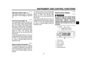
EAU46632
TIPThis model is equipped with:
a lean angle sensor to stop the en-
gine in case of a turnover. In this
case, the multi-function display in-
dicates error code 30, but this is
not a malfunction. Turn the key to
“OFF” and then to “ON” to clear the
error code. Failing to do so will pre-
vent the engine from starting even
though the engine will crank when
pushing the start switch.
an engine auto-stop system. The
engine stops automatically if left
idling for 20 minutes. In this case,
the multi-function display indicates
error code 70, but this is not a mal-
function. Push the start switch to
clear the error code and to restartthe engine.
EAU52905
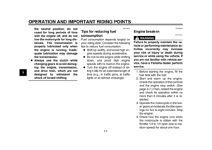
Starting a cold engine NOTICE
ECA11042
For maximum engine life, never ac-
celerate hard when the engine iscold!
In order for the ignition circuit cut-off
system to enable starting, one of the
following conditions must be met:
The transmission is in the neutral
position.
The transmission is in gear with
the clutch lever pulled and the sid-
estand up.
See page 3-19 for more informa-
tion.
1. Push the main switch to “ON” and make sure that the engine stop
switch is set to “ ”.
The following warning lights
should come on for a few seconds,
then go off.
Fuel level warning light
Engine trouble warning light
NOTICE
ECA17781
If a warning light does not come on
initially when the main switch is
1DX-9-E1.book 1 ページ 2012年7月31日 火曜日 午前9時31分
Page 40 of 98

OPERATION AND IMPORTANT RIDING POINTS
5-2
1
2
3
45
6
7
8
9pushed to “ON”, or if a warning light
remains on, see page 3-1 for the cor-
responding warning light circuit
check.
2. Shift the transmission into the neu- tral position. The neutral indicator
light should come on. If not, ask a
Yamaha dealer to check the elec-
trical circuit.
3. Turn the starter on and completely close the throttle. (See page 3-12.)
4. Start the engine by pushing the start switch or by pushing the kick-
starter lever down.
If the engine fails to start when us-
ing the start switch, release it, wait
a few seconds, and then try again.
Each starting attempt should be as
short as possible to preserve the
battery. Do not crank the engine
more than 10 seconds on any one
attempt. If the engine does not
start with the starter motor, try us-
ing the kickstarter.NOTICE
ECA17801
If the starter motor will not turn when
the start switch is pushed, stop pushing it immediately in order to
avoid placing extra load on the start-
er motor, and start the engine by us-
ing the kickstarter.TIPUse the kickstarter when the ambient
temperature is below 10
C (50 F) orwhen at high altitude.
5. When the engine is warm, turn the starter off.TIPThe engine is warm when it responds
quickly to the throttle with the starterturned off.
Starting with the kickstarter
When using the kickstarter to start the
engine, follow the procedures as de-
scribed below.1. Fold out the kickstarter lever, push it down lightly with your foot until
resistance is felt. 2. With the throttle fully closed, push
the kickstarter down lightly until the
gears engage, and then push it
down smoothly but forcefully.
WARNING
EWA16381
Do not open the throttle while kick-
ing the kickstarter lever. Otherwise,the kickstarter lever may kick back.
1DX-9-E1.book 2 ページ 2012年7月31日 火曜日 午前9時31分