Page 73 of 98

PERIODIC MAINTENANCE AND ADJUSTMENT
6-30
2
3
4
567
8
9
EAU23283
Checking the steering Worn or loose steering bearings may
cause danger. Therefore, the operation
of the steering must be checked as fol-
lows at the intervals specified in the pe-
riodic maintenance and lubrication
chart.1. Place a stand under the engine to raise the front wheel off the
ground. (See page 6-36 for more
information.) WARNING! To
avoid injury, securely support
the vehicle so there is no danger
of it falling over.
[EWA10751]
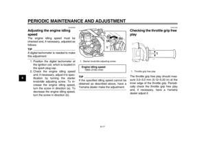
2. Hold the lower ends of the front fork legs and try to move them for-
ward and backward. If any free
play can be felt, have a Yamaha
dealer check or repair the steering.
EAU23291
Checking the wheel bearings The front and rear wheel bearings must
be checked at the intervals specified in
the periodic maintenance and lubrica-
tion chart. If there is play in the wheel
hub or if the wheel does not turn
smoothly, have a Yamaha dealer check
the wheel bearings.
EAU52491
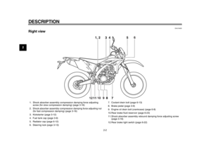
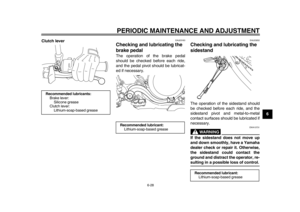
Battery The battery is located under the seat.
(See page 3-13.)
This model is equipped with a VRLA
(Valve Regulated Lead Acid) battery.
There is no need to check the electro-
lyte or to add distilled water. However,
the battery lead connections need to be
checked and, if necessary, tightened.
WARNING
EWA10760
Electrolyte is poisonous and
dangerous since it contains sul-
furic acid, which causes severe
burns. Avoid any contact with
1. Negative battery lead (black)
2. Positive battery lead (red)
3. Battery
1
2
3
1DX-9-E1.book 30 ページ 2012年7月31日 火曜日 午前9時31分
Page 74 of 98

PERIODIC MAINTENANCE AND ADJUSTMENT
6-31
1
2
3
4
56
7
8
9skin, eyes or clothing and al-
ways shield your eyes when
working near batteries. In case
of contact, administer the fol-
lowing FIRST AID.
EXTERNAL: Flush with plenty
of water.
INTERNAL: Drink large quan- tities of water or milk and im-
mediately call a physician.
EYES: Flush with water for 15 minutes and seek prompt
medical attention.
Batteries produce explosive hy-
drogen gas. Therefore, keep
sparks, flames, cigarettes, etc.,
away from the battery and pro-
vide sufficient ventilation when
charging it in an enclosed
space.
KEEP THIS AND ALL BATTER-
IES OUT OF THE REACH OFCHILDREN.
To charge the battery
Have a Yamaha dealer charge the bat-
tery as soon as possible if it seems to
have discharged. Keep in mind that the battery tends to discharge more quickly
if the vehicle is
equipped with optional
electrical accessories.
NOTICE
ECA16521
To charge a VRLA (Valve Regulated
Lead Acid) battery, a special (con-
stant-voltage) battery charger is re-
quired. Using a conventional batterycharger will damage the battery.
To store the battery 1. If the vehicle will not be used for more than one month, remove the
battery, fully charge it, and then
place it in a cool, dry place.
NOTICE: When removing the
battery, be sure the main switch
is pushed to “OFF”, then dis-
connect the negative lead be-
fore disconnecting the positive
lead.
[ECA17810]
2. If the battery will be stored for more than two months, check it at least
once a month and fully charge it if
necessary.
3. Fully charge the battery before in- stallation. NOTICE: When install- ing the battery, be sure the main
switch is pushed to “OFF”, then
connect the positive lead before
connecting the negative
lead.
[ECA17770]
4. After installation, make sure that the battery leads are properly con-
nected to the battery terminals.
NOTICE
ECA16530
Always keep the battery charged.
Storing a discharged battery cancause permanent battery damage.
1DX-9-E1.book 31 ページ 2012年7月31日 火曜日 午前9時31分
Page 75 of 98

If the fuse is blown, replace it as fol-
lows.1. Push the main s")
PERIODIC MAINTENANCE AND ADJUSTMENT
6-32
2
3
4
567
8
9
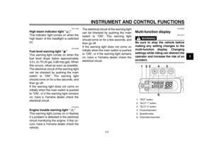
EAU52422
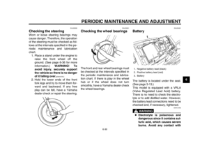
Replacing the fuse The fuse is located under the seat.
(See page 3-13.)
If the fuse is blown, replace it as fol-
lows.1. Push the main switch to “OFF” and turn off all electrical circuits.
2. Remove the blown fuse, and then install a new fuse of the specified
amperage. WARNING! Do not
use a fuse of a higher amperage
rating than recommended to
avoid causing extensive dam-
age to the electrical system and
possibly a fire.
[EWA15131]
3. Push the main switch to “ON” and
turn on the electrical circuits to
check if the devices operate.
4. If the fuse immediately blows again, have a Yamaha dealer
check the electrical system.
EAU53220
Replacing the headlight bulb This model is equipped with a halogen
bulb headlight. If the headlight bulb
burns out, replace it as follows.NOTICE
ECA10650
Take care not to damage the follow-
ing parts:
Headlight bulb
Do not touch the glass part of
the headlight bulb to keep it free
from oil, otherwise the transpar-
ency of the glass, the luminosity
of the bulb, and the bulb life will
be adversely affected. Thor-
oughly clean off any dirt and fin-
gerprints on the headlight bulb
using a cloth moistened with al-
cohol or thinner.
Headlight lens
Do not affix any type of tinted
film or stickers to the headlight
lens.
Do not use a headlight bulb of awattage higher than specified.
1. Fuse
2. Spare fuse
1
2
Specified fuse:15.0 A
1DX-9-E1.book 32 ページ 2012年7月31日 火曜日 午前9時31分
Page 76 of 98
PERIODIC MAINTENANCE AND ADJUSTMENT
6-33
1
2
3
4
56
7
8
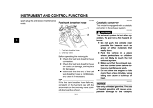
91. Remove the headlight cowling to-
gether with the headlight unit by
removing the bolts and pulling up-
ward as shown.
2. Disconnect the headlight coupler, and then remove the headlight
bulb cover.
3. Remove the headlight bulb holder by turning it counterclockwise, and
then remove the burnt-out bulb. 4. Place a new headlight bulb into po-
sition, and then secure it with the
bulb holder.
5. Install the bulb cover, and then connect the coupler.
6. Install the headlight cowling (to- gether with the headlight unit) by
placing it in the original position,
and then installing the bolts.
7. Have a Yamaha dealer adjust the headlight beam if necessary.
1. Do not touch the glass part of the bulb.
1. Headlight cowling
2. Bolt
22
1
1. Headlight coupler
2. Headlight bulb cover
1. Headlight bulb holder
1
2
1
1DX-9-E1.book 33 ページ 2012年7月31日 火曜日 午前9時31分
Page 77 of 98
PERIODIC MAINTENANCE AND ADJUSTMENT
6-34
2
3
4
567
8
9
EAU24181
Tail/brake light This model is equipped with an
LED-type tail/brake light.
If the tail/brake light does not come on,
have a Yamaha dealer check it.
EAU24204
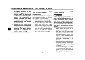
Replacing a turn signal light
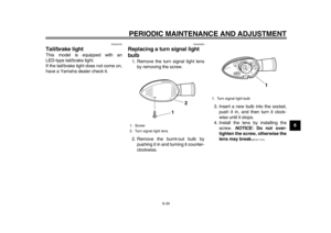
bulb 1. Remove the turn signal light lensby removing the screw.
2. Remove the burnt-out bulb by pushing it in and turning it counter-
clockwise. 3. Insert a new bulb into the socket,
push it in, and then turn it clock-
wise until it stops.
4. Install the lens by installing the screw. NOTICE: Do not over-
tighten the screw, otherwise the
lens may break.
[ECA11191]
1. Screw
2. Turn signal light lens
1
2
1. Turn signal light bulb
1
1DX-9-E1.book 34 ページ 2012年7月31日 火曜日 午前9時31分
Page 78 of 98
PERIODIC MAINTENANCE AND ADJUSTMENT
6-35
1
2
3
4
56
7
8
9
EAU24313
Replacing the license plate
light bulb 1. Remove the license plate light unit
by removing the screws.
2. Remove the license plate light bulb socket (together with the bulb) by
pulling it out. 3. Remove the burnt-out bulb by pull-
ing it out.
4. Insert a new bulb into the socket.
5. Install the socket (together with the bulb) by pushing it in.
6. Install the license plate light unit by installing the screws.
EAU45224
Replacing an auxiliary light
bulb If the auxiliary light bulb burns out, re-
place it as follows.1. Remove the headlight unit. (See page 6-32.)
2. Remove the auxiliary light bulb socket (together with the bulb) by
pulling it out.
3. Remove the burnt-out bulb by pull- ing it out.
1. Screw
1
1. License plate light unit
2. License plate light bulb socket
1 2
1. Auxiliary light bulb socket
1
1DX-9-E1.book 35 ページ 2012年7月31日 火曜日 午前9時31分
Page 79 of 98
 by pushing it in.
6. Install the headlight unit.
EAU24350
Su")
PERIODIC MAINTENANCE AND ADJUSTMENT
6-36
2
3
4
567
8
9
4. Insert a new bulb into the socket.
5. Install the socket (together with the
bulb) by pushing it in.
6. Install the headlight unit.
EAU24350
Supporting the motorcycle Since this model is not equipped with a
centerstand, follow these precautions
when removing the front and rear
wheel or performing other maintenance
requiring the motorcycle to stand up-
right. Check that the motorcycle is in a
stable and level position before starting
any maintenance. A strong wooden
box can be placed under the engine for
added stability.
To service the front wheel 1. Stabilize the rear of the motorcycle by using a motorcycle stand or, if
an additional motorcycle stand is
not available, by placing a jack un-
der the frame in front of the rear
wheel.
2. Raise the front wheel off the ground by using a motorcycle
stand.
To service the rear wheel
Raise the rear wheel off the ground by
using a motorcycle stand or, if a motor-
cycle stand is not available, by placing
a jack either under each side of the frame in front of the rear wheel or under
each side of the swingarm.
1. Auxiliary light bulb
1
1DX-9-E1.book 36 ページ 2012年7月31日 火曜日 午前9時31分
Page 80 of 98

PERIODIC MAINTENANCE AND ADJUSTMENT
6-37
1
2
3
4
56
7
8
9
EAU24360
Front wheel
EAU49332
To remove the front wheel
WARNING
EWA10821
To avoid injury, securely support the
vehicle so there is no danger of itfalling over.1. Remove the rubber cap, and then loosen the front wheel axle pinch
bolts and the axle nut. 2. Lift the front wheel off the ground
according to the procedure in the
previous section “Supporting the
motorcycle”.
3. Remove the axle nut.
4. Pull the wheel axle out.
5. Remove the spacers and the wheel. NOTICE: Do not apply the
brake after the wheel has been
removed together with the
brake disc, otherwise the brake
pads will be forced shut.
[ECA11071]
EAU49342
To install the front wheel 1. Install the spacers into both sides of the wheel hub. NOTICE: When installing the spacers, be sure
to install them on the correct
side.
[ECA17700]
2. Lift the wheel up between the fork legs.
TIPMake sure that there is enough space
between the brake pads before install-
ing the brake caliper onto the brakedisc.
3. Insert the wheel axle from the right-hand side.
4. Install the axle nut.
5. Lower the front wheel so that it is on the ground, and then put the
sidestand down.
6. Tighten the axle nut to the speci- fied torque.
7. Tighten the front wheel axle pinch bolts to the specified torque, and
then install the rubber cap.
1. Front wheel axle pinch bolt
2. Axle nut
3. Rubber cap
23
1
1. Front wheel axle pinch bolt
2. Wheel axle1
2
Tightening torque: Axle nut:
90 Nm (9.0 m·kgf, 65 ft·lbf)
1DX-9-E1.book 37 ページ 2012年7月31日 火曜日 午前9時31分