Page 139 of 751
07-51543-00
1. SYSTEM DESCRIPTION
1) Overview
The lubrication system supplies oil to each lubrication section to prevent friction and wear and to remove
heat from the friction part. As the engine runs, frictional heat is generated on each lubrication section. If
this condition persists, the bearing can be burned and stuck.
In other words, it creates an oil film on each sliding surface to convert solid friction to liquid friction in order
to minimize wear and prevent temperature increasing on the friction part.
For the D20DTF engine with no oil pressure switch, the engine ECU receives the low engine oil level
signal from the oil level sensor and communicates with the instrument cluster through the CAN
communication to turn on the warning lamp.
2) Components
Oil coolerOil dipstick gaugeOil pump
Oil filter moduleOil pressure switchOil pan
Page 142 of 751

08-4
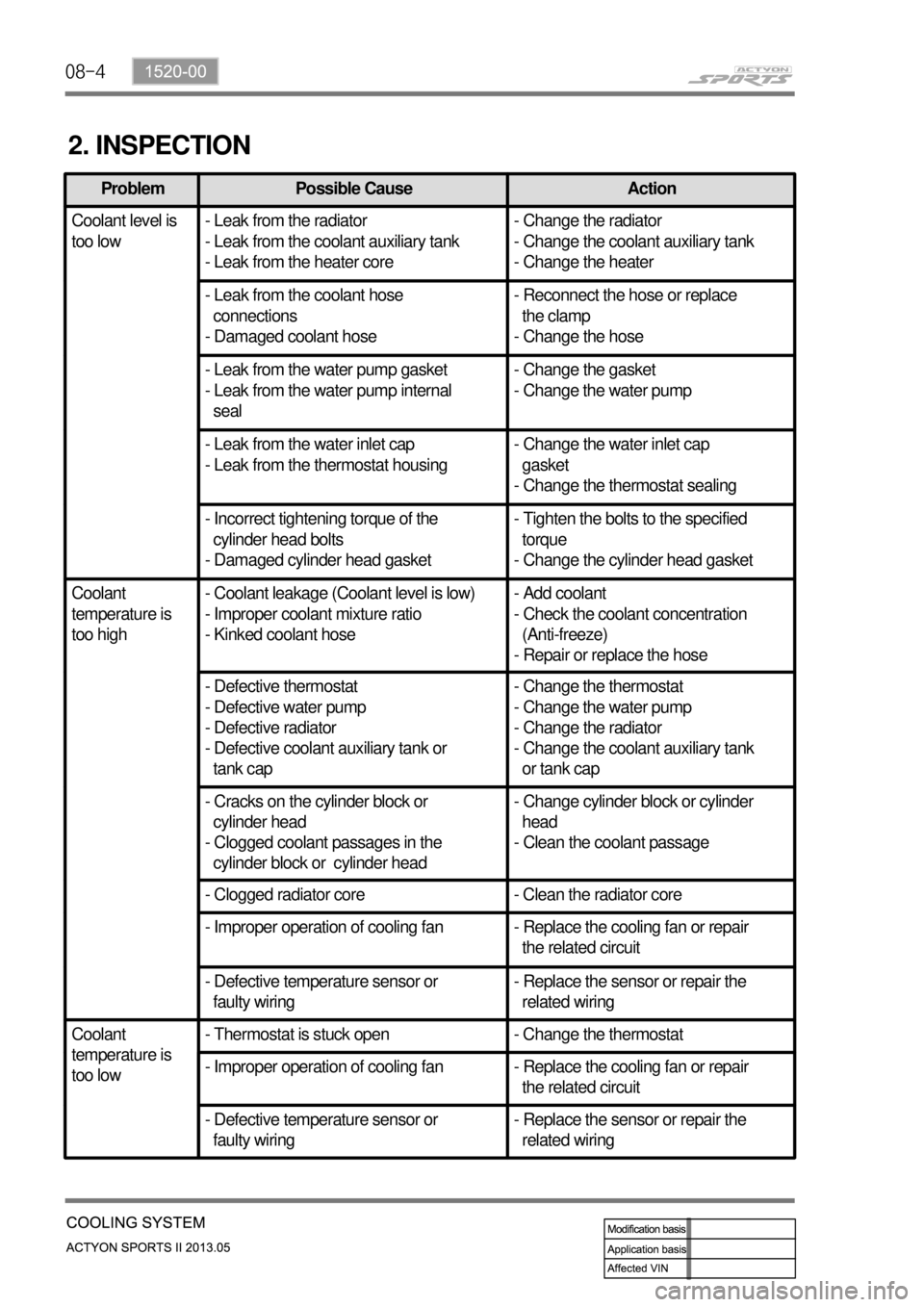
2. INSPECTION
Problem Possible Cause Action
Coolant level is
too low- Leak from the radiator
- Leak from the coolant auxiliary tank
- Leak from the heater core- Change the radiator
- Change the coolant auxiliary tank
- Change the heater
- Leak from the coolant hose
connections
- Damaged coolant hose- Reconnect the hose or replace
the clamp
- Change the hose
- Leak from the water pump gasket
- Leak from the water pump internal
seal- Change the gasket
- Change the water pump
- Leak from the water inlet cap
- Leak from the thermostat housing- Change the water inlet cap
gasket
- Change the thermostat sealing
- Incorrect tightening torque of the
cylinder head bolts
- Damaged cylinder head gasket- Tighten the bolts to the specified
torque
- Change the cylinder head gasket
Coolant
temperature is
too high- Coolant leakage (Coolant level is low)
- Improper coolant mixture ratio
- Kinked coolant hose- Add coolant
- Check the coolant concentration
(Anti-freeze)
- Repair or replace the hose
- Defective thermostat
- Defective water pump
- Defective radiator
- Defective coolant auxiliary tank or
tank cap- Change the thermostat
- Change the water pump
- Change the radiator
- Change the coolant auxiliary tank
or tank cap
- Cracks on the cylinder block or
cylinder head
- Clogged coolant passages in the
cylinder block or cylinder head- Change cylinder block or cylinder
head
- Clean the coolant passage
- Clogged radiator core - Clean the radiator core
- Improper operation of cooling fan - Replace the cooling fan or repair
the related circuit
- Defective temperature sensor or
faulty wiring- Replace the sensor or repair the
related wiring
Coolant
temperature is
too low- Thermostat is stuck open - Change the thermostat
- Improper operation of cooling fan - Replace the cooling fan or repair
the related circuit
- Defective temperature sensor or
faulty wiring- Replace the sensor or repair the
related wiring
Page 147 of 751
08-91520-00
Electric fan
Circulates the fresh air forcibly to exchange heat
with the radiator core fin.
Radiator
Releases heat through fins and cools down the hot
coolant as the coolant passes through the tube of the
radiator core.
Coolant temperature sensor
Measures the coolant
temperature and sends the
result to the engine ECU.
Page 182 of 751
13-4
1. SYSTEM DESCRIPTION
1) Overview
The EGR (Electric-Exhaust Gas Recirculation) valve reduces the NOx emission level by recirculating
some of the exhaust gas to the intake system.
To meet Euro-V regulation, the capacity and response rate of E-EGR valve in D20DTR engine have been
greatly improved. The EGR cooler with high capacity reduces the Nox, and the bypass valve reduces the
CO and HC due to EGR gas before warming up.
Also, the engine ECU adjusts the E-EGR opening by using the air mass signal through HFM sensor. If
the exhaust gas gets into the intake manifold when the EGR valve is open, the amount of fresh air
through HFM sensor should be decresed.
Benefits of E-EGR valve ▶
Improved accuracy and response through electric control
Feedback function (Potentiometer)
Preventing chattering of EGR valve and improved durability
Self-cleaning function -
-
-
-
Page 183 of 751
13-51793-00
E-EGR valve
Receives the electric signal from the ECU to
control the valve.
E-EGR cooler and bypass valve
The cooler lowers the high temperature of the
exhaust gas and the bypass valve directly
supplies the exhaust gas to the intake duct
without passing through the EGR cooler to
reduce the emission of exhaust gas before
warming up the engine.
2) Location and Components
HFM sensor
Used as a main map value to control the EGR.
The coolant temperature, engine rpm, engine
load, intake air temperature (HFM: decreased at
60˚C or more), atmospheric pressure
(atmospheric pressure sensor: altitude
compensation) are used as auxiliary map values.
EGR pipe
Transports the exhaust gas from the EGR cooler
and EGR bypass valve to the intake duct.
See the section "Engine control" for E-EGR
valve control logic.
EGR cooler
EGR bypass
For details, see the section "Engine control". *
Page 190 of 751
14-6
Excessive overload of CDPF (warning lamp illuminated)
If the vehicle is driven at a speed of 5 to 10 km/h for an extended period of time, the soot
accumulated in the CDPF cannot be burned as the CDPF cannot reach the regeneration
temperature. Then, an excessive amount of soot can be accumulated in the CDPF.
This case is much worse than the simple over-load of the CDPF. To inform this to the driver, the
engine warning lamp comes on and the engine power is decreased to protect the system.
To solve this problem, blow soot between the engine and exhaust system several times and erase
the related DTC. Then, check if the same DTC is regenerated again. If so, check the DTC related to
the differential pressure sensor. 1.
2.
3.
Page 193 of 751
14-92412-02
Differential pressure
sensor
Calculates the amount of
PM collected by reading the
pressure difference between
before and after the CDPF.Engine ECU
DCM 3.7
Post-injectionThrottle
valve
Regulates the rate of air
intake.
CDPF
DOC+DPFFront temperature
sensor
Protects the turbocharger.Rear temperature sensor
Measures the temperature
of fuel combustion.
2. COMPONENT
For details, refer to section "Engine Control". *
Page 194 of 751

14-10
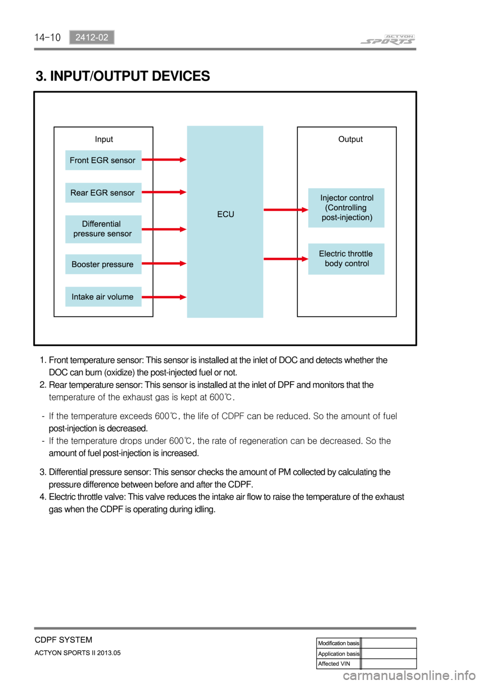
3. INPUT/OUTPUT DEVICES
Front temperature sensor: This sensor is installed at the inlet of DOC and detects whether the
DOC can burn (oxidize) the post-injected fuel or not.
Rear temperature sensor: This sensor is installed at the inlet of DPF and monitors that the
temperature of the exhaust gas is kept at 600℃. 1.
2.
<0070008d0047009b008f008c0047009b008c00940097008c00990088009b009c0099008c0047008c009f008a008c008c008b009a0047005d005700570b4500530047009b008f008c004700930090008d008c00470096008d0047006a006b0077006d004700
8a0088009500470089008c00470099008c008b009c008a008c>d. So the amount of fuel
post-injection is decreased.
<0070008d0047009b008f008c0047009b008c00940097008c00990088009b009c0099008c0047008b009900960097009a0047009c0095008b008c00990047005d005700570b4500530047009b008f008c004700990088009b008c00470096008d0047009900
8c008e008c0095008c00990088009b0090009600950047008a>an be decreased. So the
amount of fuel post-injection is increased. -
-
Differential pressure sensor: This sensor checks the amount of PM collected by calculating the
pressure difference between before and after the CDPF.
Electric throttle valve: This valve reduces the intake air flow to raise the temperature of the exhaust
gas when the CDPF is operating during idling. 3.
4.