Page 36 of 751
02-50000-00
ComponentSizeBolt
Quantity Specified torque
(Nm) Remark
(Total torque)
Hot water inlet pipe M6×16 2 10±1Nm -
Alternator M10×90 1 25±2.5Nm -
M10×116 1 46±4.6Nm -
A/C bracket M8×25 4 7.8~11.8Nm -
A/C sub bracket M6×25 4 10±1Nm -
Intake manifold M8×35 2 25±2.5Nm -
M8×110 6 25±2.5Nm -
Oil filter module M8×40 6 25±2.5Nm -
M8×20 1 25±2.5Nm -
M8×140 2 25±2.5Nm -
Knock sensor M8×28 2 20±5Nm -
Cam position sensor M8×14 1 10~14Nm -
Booster pressure sensor M6×20 2 10±1Nm -
Exhaust manifold M810 40±4Nm -
Turbocharger M83 25±2.5Nm -
Support nut M81 25±2.5Nm -
T/C oil supply pipe M161 25±2.5Nm
(Fitting Screw) -
M10 1 17±2Nm
(Hollow Bolt) -
T/C oil return pipe M6×16(turbo side) 2 10±1Nm -
M6×16(block side) 2 10±1Nm -
EGR valve M8×30325±2.5Nm -
EGR pipe bolt (Intake side) M6×16
2 10±1Nm -
EGR pipe bolt
(EGR cooler side) M8×25
2 25±2.5Nm -
Support bolt M8×35125±2.5Nm
(Turbo Side) -
M8×16 125±2.5Nm
(Block Side) -
Page 37 of 751
02-6
ComponentSizeBolt
Quantity Specified torque
(Nm) Remark
(Total torque)
Glow plug M5 4 20±2Nm -
Vacuum pump M6×253 10±1Nm -
Timing gear case cover M12×55 3 85±8.5Nm -
M6×25 7 10±1Nm -
M6×45 1 10±1Nm -
M6×50 3 10±1Nm -
Cylinder head cover M6×35 21 10±1Nm -
Oil gauge tube M6×16 1 10±1Nm -
Oil filter cap 1 25±2.5Nm -
Fuel rail M8×35SOC 2 25±2.5Nm -
Injector clamp bolt M6×60 2 10±1Nm,
120˚+10˚ -
High pressure pipe
(between HP pump and fuel rail) M17 1
30±3Nm -
High pressure pipe
(between fuel rail and injector) M17 4
30±3Nm -
Crank position sensor M5×14 1 5±1.0Nm -
Main wiring M6×16 5 10±1Nm -
Intake duct M8x25 4 25±2.5Nm -
Power steering pump M8×100 3 25±2.5Nm -
Cylinder head front cover M6×10 5 10±1Nm -
Ladder frame M8×16 5 30±3Nm -
Oil pump M8×35 3 25±2.5Nm -
EGR Cooler
MTG Bolt M8×16
225±2.5Nm -
M8×70 225±2.5Nm -
Idle pulley/Tensioner pulley 1
45±4.5Nm -
Page 38 of 751

02-70000-00
3. CHECK AND INSPECTION
1) Cylinder
(1) Compression pressure test
Specified value ▶
Compression ratio16.5 : 1
Test conditionat normal operating temperature (80˚C)
Compression pressureStandard32 bar
Minimum18 bar
Differential limit between cylindersMaximum 3 bar
The compression pressure test is to check the conditions of internal components (piston, piston ring,
intake and exhaust vale, cylinder head gasket). This test provides current engine operating status.
Before cranking the engine, make sure that the test wiring, tools and persons are keeping away
from moving components of engine (e.g., belt and cooling fan).
Park the vehicle on the level ground and apply the parking brake.
Do not allow anybody to be in front of the vehicle. -
-
-
Measurement ▶
<007e0088009900940047009b008f008c0047008c0095008e00900095008c0047009c00970047009b00960047009500960099009400880093004700960097008c00990088009b00900095008e0047009b008c00940097008c00990088009b009c0099008c00
47004f005f005700b6006a00500055>
Disconnect the fuel rail pressure sensor connector to cut off the fuel injection.
Remove the air cleaner duct and glow plugs. -
-
-
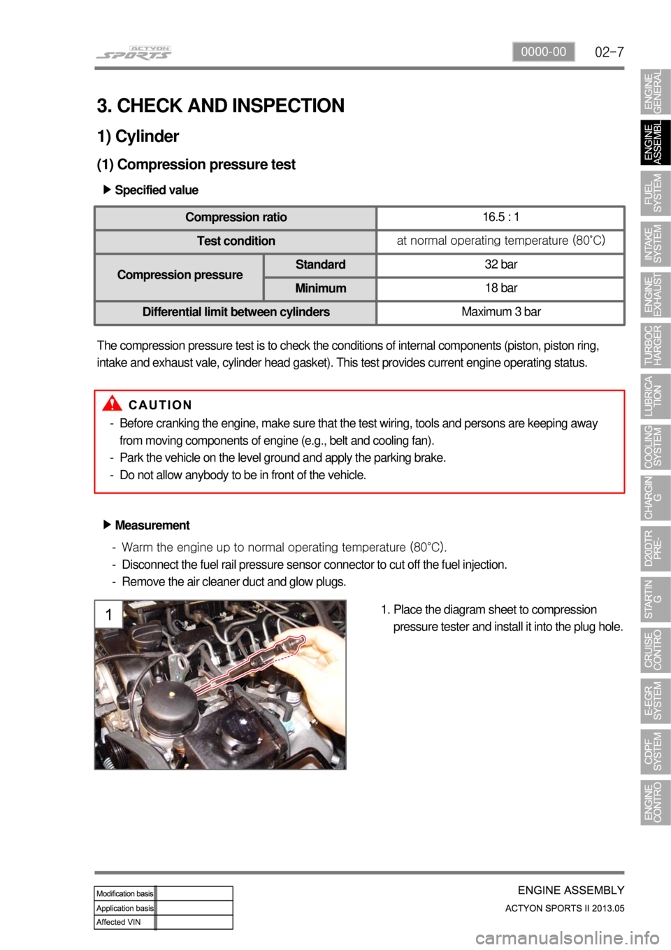
Place the diagram sheet to compression
pressure tester and install it into the plug hole. 1.
Page 55 of 751
02-24
Intake/exhaust CamshaftsFinger follower & HLACamshaft sprocket
Cylinder head gasket
Vacuum pump driveHP pump drive gearCamshaft position sensor
Components ▶
Cylinder head
Cylinder head contains cam position sensor, vacuum pump, intake manifold, exhaust manifold and valve
assembly. Vacuum pump and the high pressure (HP) pump are driven by Camshaft and valves are install
in vertical direction. This enables the compact layout in cylinder head assembly.
6. CYLINDER HEAD
Page 77 of 751
02-46
4) Cylinder Block
(1) Overview
The major dimensions in D20DTR are similar to
D20DTR engine. It has two mounting
bosses for knock sensor and meets the
requirements for EURO5 regulation.
(2) Layout
Right sideSpring pin
Expansion plug
Screw plug
Page 89 of 751
03-12
(5) High Pressure System Pressure Test
Fuel rail pressure test ▶
Disconnect the fuel rail pressure sensor
connector and then IMV connector. 1.
Connect the pressure tester to the fuel rail
pressure sensor connector. 2.
Crank the engine 2 times for 5 seconds. 3.
Read the highest pressure value displayed
on the tester display.
If the highest pressure value is 1,050 bar or
less, refer to the section "Fuel System
Check Process". -
-
Page 92 of 751
03-152210-01
Static test for backleak of injector ▶
Disconnect the injector return hose and cover
the openings with caps shaped screw (included
in the special tool). 1.
Connect the hose of the container for
measuring backleak to the return nipple of the
injector.
(prevent air entry to the low pressure line) 2.
Disconnect the IMV connector of the high
pressure pump and then fuel pressure
sensor connector. 3.
The connector of the injector can be easily
contaminated. Always keep it clean.
Crank the engine 2 times for 5 seconds.
Check the time for flow if injector backleak and
confirm that it is within the specified range. 4.
5.
If the value is out of the specified range,
replace the injector.
SpecificationBelow 20 sec.
Page 94 of 751
03-172210-01
HP pump pressure test ▶
Prepare a special tool for high pressure test
and clean it thoroughly to prevent foreign
materials from entering. 1.
Disconnect the high pressure fuel supply pipe
on the HP pump and install the close rail in the
tool kit. 2.
Connect the other end of the close rail to the
fuel rail for test. 3.
Disconnect the return hose for HP pump and
connect the clear hose and connect its the
other end to the return port of the fuel rail for
test. 4.
Connect the digital tester connector to the
sensor connector of the fuel rail for test.
Crank the engine 2 times for 5 seconds after
removing the IMV connector and fuel rail
pressure sensor connector.
Read the pressure value displayed on the
tester display is within the specified 5.
6.
7.
Specification1,050 bar or more