Page 38 of 751

02-70000-00
3. CHECK AND INSPECTION
1) Cylinder
(1) Compression pressure test
Specified value ▶
Compression ratio16.5 : 1
Test conditionat normal operating temperature (80˚C)
Compression pressureStandard32 bar
Minimum18 bar
Differential limit between cylindersMaximum 3 bar
The compression pressure test is to check the conditions of internal components (piston, piston ring,
intake and exhaust vale, cylinder head gasket). This test provides current engine operating status.
Before cranking the engine, make sure that the test wiring, tools and persons are keeping away
from moving components of engine (e.g., belt and cooling fan).
Park the vehicle on the level ground and apply the parking brake.
Do not allow anybody to be in front of the vehicle. -
-
-
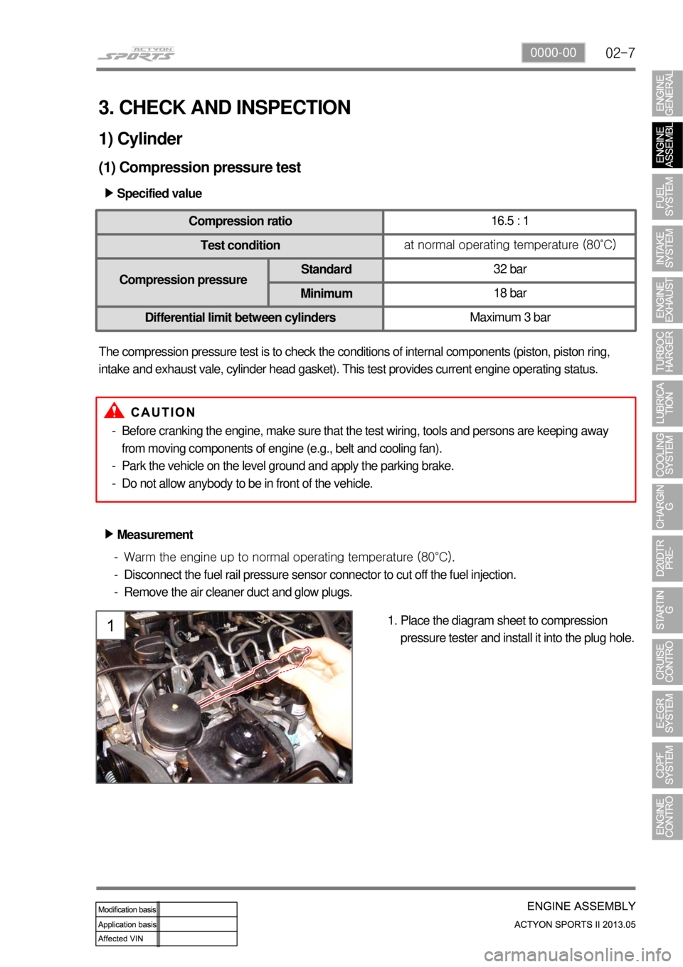
Measurement ▶
<007e0088009900940047009b008f008c0047008c0095008e00900095008c0047009c00970047009b00960047009500960099009400880093004700960097008c00990088009b00900095008e0047009b008c00940097008c00990088009b009c0099008c00
47004f005f005700b6006a00500055>
Disconnect the fuel rail pressure sensor connector to cut off the fuel injection.
Remove the air cleaner duct and glow plugs. -
-
-
Place the diagram sheet to compression
pressure tester and install it into the plug hole. 1.
Page 57 of 751
02-26
Intake/Exhaust Camshafts
2) Camshaft
(1) Overview
Hollow type camshaft contains cam, octagon cam, HP pump gear and intake/\
exhaust gears.
Camshaft operates the intake/exhaust valves, vacuum pump and HP pump, an\
d transfers the engine
oil to vacuum pump through the internal oil passage.
(2) Location
Exhaust CamshaftHP Pump Gear
Octagon cam
(for tooling)
Thrust journal
Connected to
vacuum pumpIntake Camshaft
Cross flow type water jacket (improving cooling performance)
▶
Page 70 of 751
02-390000-00
1) Piston
(1) Overview
Piston assembly contains piston, #1 ring, #2
ring, oil ring, piston pin and snap ring. The
expansion energy from engine is transferred to
the crankshaft through connecting rod to convert
the linear movement to rotating energy.
(2) Layout
#1 ring
Oil ring
Snap ring
#2 ringMaterial: B2+
Skirt coating:
MoS2
Piston cooling gallery for
connecting rod
Wide bowl type (CR 16.5)
Cooling jet
Page 140 of 751

07-6
2. FUNCTIONS OF LUBRICATION
1) Lubrication
It creates a viscous barrier between moving parts that reduces friction, which means less heat and
longer life for those parts. As a lubricant, oil must maintain a protective film to prevent metal-to-metal
contact. It must be fluid enough to allow easy starting and to circulate quickly through the engine, yet
remain thick enough at higher operating temperatures and speeds to provide adequate lubrication.
2) Cooling
Combustion heat and friction energy must be removed from the engine in order to prevent its
overheating. Most of heat energy is taken by the engine oil.
Clean oil passages, proper viscosity and low contamination provide sufficient flow rate of the engine oil
and effective cooling.
3) Sealing
It helps to seal the space between the pistons and the cylinder walls so that compression is more
effective and power is not lost during combustion.
4) Anti-corrosion
As a corrosion inhibitor, oil coats internal engine parts to prevent surface rust on the inside of the engine
which can be caused by blow-by products and water formed in combustion. It must also be capable of
neutralizing the acids that are formed by combusti on blow-by and oil oxidation at high temperatures.
5) Cleaning
The small particles of dirt or other contaminants are suspended in oil and carried away to be filtered out.
As a detergent, engine oil must be able to gather and suspend dirt and other contaminants until the oil
can leave them as it passes through the filter and returns to the internal engine environment.
Page 141 of 751
08-31520-00
1. SPECIFICATION
Unit Description Specification
Cooling system Type Water cooling, forced circulation
Coolant Capacity approx. 8.5 L
Radiator Core size 555W x 582.4H x 27T (over 326,250mm2)
Flow type Cross flow
Min. cooling capacity over 68,000 kcal/h
Antifreeze Type SYC1025 (Long life coolant)
Mixing ratio
(water:antifreeze)50 : 50
Cooling fan module Type Electric
CapacityØ472 x 400W x 5B
Control type PWM type
Coolant reservoir Capacity over 1.5 L
Circulation Closed roof type
Pressure cap Screw type, 1.4bar
Vacuum valve Screw type, 1.4bar
Thermostat Type Wax pallet type
Opening temperature90˚C
Fully open temperature100˚C
Valve lift 8 mm
Page 142 of 751

08-4
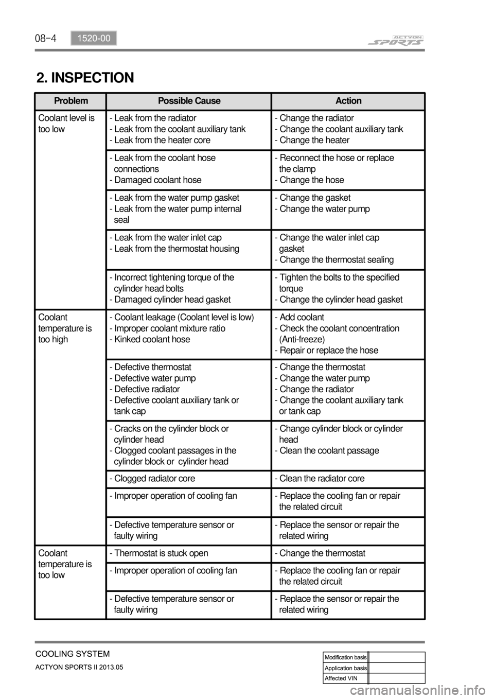
2. INSPECTION
Problem Possible Cause Action
Coolant level is
too low- Leak from the radiator
- Leak from the coolant auxiliary tank
- Leak from the heater core- Change the radiator
- Change the coolant auxiliary tank
- Change the heater
- Leak from the coolant hose
connections
- Damaged coolant hose- Reconnect the hose or replace
the clamp
- Change the hose
- Leak from the water pump gasket
- Leak from the water pump internal
seal- Change the gasket
- Change the water pump
- Leak from the water inlet cap
- Leak from the thermostat housing- Change the water inlet cap
gasket
- Change the thermostat sealing
- Incorrect tightening torque of the
cylinder head bolts
- Damaged cylinder head gasket- Tighten the bolts to the specified
torque
- Change the cylinder head gasket
Coolant
temperature is
too high- Coolant leakage (Coolant level is low)
- Improper coolant mixture ratio
- Kinked coolant hose- Add coolant
- Check the coolant concentration
(Anti-freeze)
- Repair or replace the hose
- Defective thermostat
- Defective water pump
- Defective radiator
- Defective coolant auxiliary tank or
tank cap- Change the thermostat
- Change the water pump
- Change the radiator
- Change the coolant auxiliary tank
or tank cap
- Cracks on the cylinder block or
cylinder head
- Clogged coolant passages in the
cylinder block or cylinder head- Change cylinder block or cylinder
head
- Clean the coolant passage
- Clogged radiator core - Clean the radiator core
- Improper operation of cooling fan - Replace the cooling fan or repair
the related circuit
- Defective temperature sensor or
faulty wiring- Replace the sensor or repair the
related wiring
Coolant
temperature is
too low- Thermostat is stuck open - Change the thermostat
- Improper operation of cooling fan - Replace the cooling fan or repair
the related circuit
- Defective temperature sensor or
faulty wiring- Replace the sensor or repair the
related wiring
Page 145 of 751

08-71520-00
3. CAUTIONS
If 100% of anti-freeze is added, the water pump vane can be damaged and thermal conductivity
can be decreased resulting in poor circulation in the cooling system which leads to overheated
engine.
Use of non-recommended coolant could cause damage to the cooling system and overheating of
the engine.
Opening the coolant reservoir cap while the engine is running or hot can cause burns by hot steam
or water.
To open the coolant reservoir cap, wrap the cap with a wet towel or thick cloth after the engine is
cooled down sufficiently.
If cool water is added to the heated engine, the engine or radiator can be deformed.
The anti-freeze in the coolant can damage the painted surface, so avoid the contact of the coolant
to the painted body.
The anti-freeze and water should be mixed in proper mixture ratio. Never add only water when
adding coolant.
If the anti-freeze content is too low, the coolant can be frozen while the engine can be overheated if
anti-freeze content is too high. -
-
-
-
-
-
-
-
Page 181 of 751
13-31793-00
1. SPECIFICATION
Item Specification
E-EGR valveMotorEGR response time 50 ms
Driven by DC motor
Valve EGR gas flow rate 120 kg/h
Cooling capacity 8.3 kW or more
Cooling fin type Wavy fin
Cooler type U-shaped
E-EGR bypass valve Solenoid valve Drivien byVacuum
(Solenoid valve)
E-EGR cooler