Page 242 of 751
15-42
Relay box in engine compartment
(13) PTC heater control
A. Overview
The supplementary electrical heater is installed in DI engine equipped vehicle as a basic equipment. The
PTC system is operated according to two temperature values measured at the coolant temperature
sensor and HFM sensor. This device is mounted in the heater air outlet and increase the temperature of
air to the passenger compartment. Because PTC system is heated by electrical power, high capacity
alternator is required. PTC does not operate during engine cranking, while the battery voltage is lower
than 11 V or during preheating process of glow plugs.
B. Components
HFM (intake air
temperature)
Coolant temperature
sensorPTC heater
PTC 2 relay (PTC
heater 2, 3)
PTC heater
3 (40A)
PTC heater
2 (40A)
PTC heater
1 (40A)
D20DTR ECU
PTC 1 relay
(PTC heater 1)
Page 244 of 751
15-44
D. Control conditions
Operation Operating condition PTC Heater
HI
(PTC2)- Coolant temperature < 15℃PTC HI ON
LO
(PTC1)- Coolant temperature 15℃ ≤ 65℃, intake air
temperature ≤ -10℃
- Coolant temperature 15℃ < 65 to 60℃, intake air
temperature <-10℃ to 0℃
- Coolant temperature 15℃ ≤ 60℃, intake air
temperature ≤ 0℃ to 5℃PTC LO ON
Stop- A/C blower switch OFF
- Defective ambient air temperature sensor
(including open or short circuit)
- Engine cranking
- Low battery voltage (below 11V)
- During pre-glow process (glow indicator ON)
Operation diagram for PTC heater LO (step 2) ▶
Page 247 of 751
15-470000-00
(15) CDPF control
A. Overview
As the solution for environmental regulations and PM Particle Material) of diesel engine, the low emission
vehicle is getting popular. This vehicle is equipped with an extra filter to collect the soot and burn it again
so that the amount of PM in the exhaust gas passed through the DOC (Diesel Oxidation Catalyst) is
reduced. The CDPF (Catalyst & Diesel Particulate Filter) is an integrated filter including DOC (Diesel
Oxidation Catalyst) and DPF (Diesel Particulate Filter).
For details, refer to Chapter "CDPF".
B. Components
Oxygen
sensorFront
EGT sensorCDPF
(DOC + DPF)Rear
EGT sensor
Differential pressure
sensorD20DTR ECUElectric throttle body
Page 249 of 751

15-490000-00
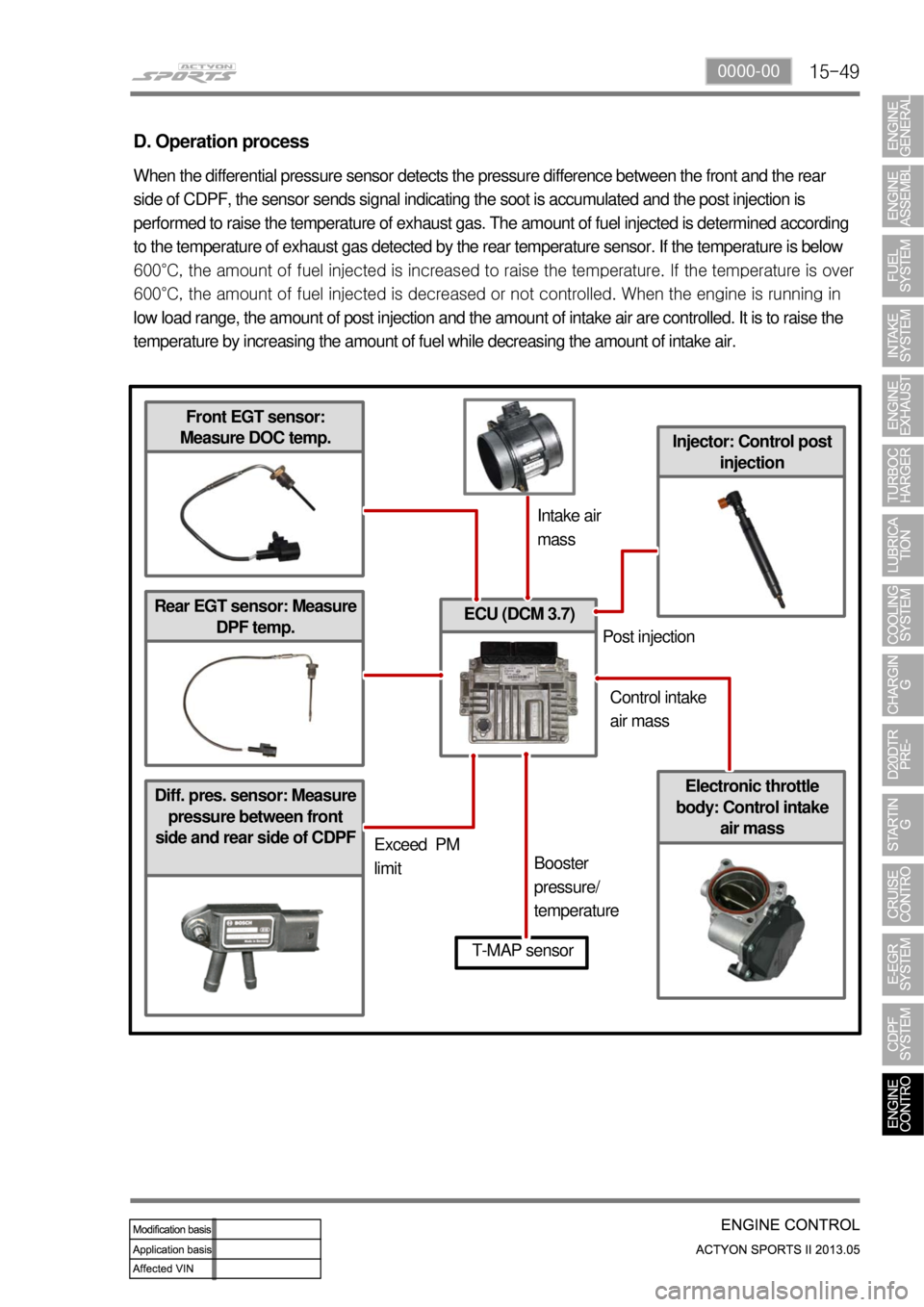
Diff. pres. sensor: Measure
pressure between front
side and rear side of CDPF
ECU (DCM 3.7)
Injector: Control post
injection
D. Operation process
When the differential pressure sensor detects the pressure difference between the front and the rear
side of CDPF, the sensor sends signal indicating the soot is accumulated and the post injection is
performed to raise the temperature of exhaust gas. The amount of fuel injected is determined according
to the temperature of exhaust gas detected by the rear temperature sensor. If the temperature is below
600°C, the amount of fuel injected is increased to raise the tem
perature. If the temperature is over
600°C, the amount of fuel injected is decreased or not controlled. When the engine is running in
low load range, the amount of post injection and the amount of intake air are controlled. It is to raise the
temperature by increasing the amount of fuel while decreasing the amount of intake air.
Front EGT sensor:
Measure DOC temp.
Rear EGT sensor: Measure
DPF temp.
Electronic throttle
body: Control intake
air mass
T-MAP sensor
Intake air
mass
Exceed PM
limitBooster
pressure/
temperaturePost injection
Control intake
air mass
Page 257 of 751
01-8
Front View ▶
NO. FUNCTION NO. FUNCTION
1 HFM Sensor 12 Intake Manifold
2 Intake Air Duct 13 Cylinder Head
3 Cylinder Head Cover 14 Exhaust Manifold
4 Ignition Coi 15 Dipstick Guide Tube and Gauge
5 Spark Plug Connector 16 Connecting Rod
6 Fuel Distributor 17 Crankshaft
7 Injector 18 Engine Mounting Bracket
8 Exhaust Camshaft 19 Starter
9 Intake Camshaft 20 Crankcase
10 Valve Tappet 21 Oil Pump Sprocket
11 Intake Valve 22 Oil Pan
NO. FUNCTION NO. FUNCTION
23 Camshaft Adjuster 29 Oil Pump Drive Chain
24 Oil Filler Cap 30 Oil Strainer
25 Engine Hanger Bracket 31 Oil Pump
26 Cooling Fan and Viscous Clutch 32 Ring Gear and Flywheel of Drive Plate
27 Oil Filter 33 Piston
28 Timing Chain
Side View ▶
Page 274 of 751

02-52211-06
1. FUEL SYSTEM
The function of the fuel metering system is to deliver the correct amount of fuel to the engine under all
operating conditions.
The fuel is delivered to the engine by the individual fuel injectors mounted into the intake manifold nea
r
each cylinder.
The main fuel control sensors are the Mass Air Flow (MAF) sensor and the oxygen (O2) sensors.
The MAF sensor monitors the mass flow of the air being drawn into the engine. An electrically heated
element is mounted in the intake air stream, where it is cooled by the flow of incoming air. Engine Control
Module (ECM) modulates the flow of heating current to maintain the temperature differential between the
heated film and the intake air at a constant level. The amount of heating current required to maintain the
temperature thus provides an index for the mass air flow. This
concept automatically compensates for variations in air density, as this is one of the factors that
determines the amount of warmth that the surrounding air absorbs from the heated element. MAF
sensor is located between the air filter and the throttle valve.
Under high fuel demands, the MAF sensor reads a high mass flow condition, such as wide open throttle.
The ECM uses this information to enrich the mixture, thus increasing the fuel injector on-time, to provide
the correct amount of fuel. When decelerating, the mass flow decreases. This mass flow change is
sensed by the MAF sensor and read by the ECM, which then decreases the fuel injector on-time due to
the low fuel demand conditions.
The O2 sensors are located in the exhaust pipe before catalytic converter. The O2 sensors indicate to
the ECM the amount of oxygen in the exhaust gas, and the ECM changes the air/fuel ratio to the engine
by controlling the fuel injectors. The best air/fuel ratio to minimize exhaust emissions is 14.7 to 1, which
allows the catalytic converter to operate most efficiently. Because
of the constant measuring and adjusting of the air/fuel ratio, the fuel injection system is called a "closed
loop" system.
The ECM uses voltage inputs from several sensors to determine how much fuel to provide to the engine.
The fuel is delivered under one of several conditions, called "modes".
Page 275 of 751

02-6
1) Starting Mode
When the ignition is turned ON, the ECM turns the fuel pump relay on for 1 second. The fuel pump then
builds fuel pressure. The ECM also checks the Engine Coolant Temperature (ECT) sensor and the
Throttle Position (TP) sensor and determines the proper air/fuel ratio for starting the engine. This ranges
from1.5 to 1 at -36 °C (-33 °F) coolant temperature to 14.7 to 1 at 94 °C (201 °F) coolant
temperature. The ECM controls the amountof fuel delivered in the starting mode by changing how long
the fuel injector is turned on and off. This is done by ''pulsing" the fuel injectors for very short times.
2) Run Mode
The run mode has two conditions called ''open loop" and ''closed loop".
3) Open Loop
When the engine is first started and it is above 690 rpm, the system goes into "open loop" operation. In
"open loop", the ECM ignores the signal from the HO2S and calculates the air/fuel ratio based on inputs
from the ECT sensor and the MAF sensor. The ECM stays in "open loop" until the following conditions
are met:
The O2 has a varying voltage output, showing that it is hot enough to operate properly.
The ECT sensor is above a specified temperature (22.5 °C).
A specific amount of time has elapsed after starting the engine. -
-
-
4) Closed Loop
The specific values for the above conditions vary with different engines and are stored in the
Electronically Erasable Programmable Read-Only Memory (EEPROM).
When these conditions are met, the system goes into "closed loop" operation. In "closed loop", the ECM
calculates the air/fuel ratio (fuel injector on- time) based on the signals from the O2 sensors. This allows
the air/fuel ratio to stay very close to 14.7 to 1.
5) Acceleration Mode
The ECM responds to rapid changes in throttle position and airflow and provides extra fuel.
6) Deceleration Mode
The ECM responds to changes in throttle position and airflow and reduces the amount of fuel. When
deceleration is very fast, the ECM can cut off fuel completely for short periods of time.
Page 276 of 751
02-72211-06
7) Battery Voltage Correction Mode
When battery voltage is low, the ECM can compensate for a weak spark delivered by the ignition
module by using the following methods:
Increasing the fuel injector pulse width.
Increasing the idle speed rpm.
Increasing the ignition dwell time. -
-
-
8) Fuel Cut-Off Mode
No fuel is delivered by the fuel injectors when the ignition is off. This prevents dieseling or engine runon.
Also, the fuel is not delivered if there are no reference pulses received from the CKP sensor. This
prevents flooding.