2013 SKODA ROOMSTER lock
[x] Cancel search: lockPage 56 of 219
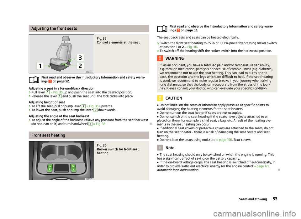
Adjusting the front seatsFig. 35
Control elements at the seat
First read and observe the introductory information and safety warn-
ings on page 52.
Adjusting a seat in a forward/back direction
›
Pull lever
1
» Fig. 35 up and push the seat into the desired position.
›
Release the lever
1
and push the seat until the lock clicks into place.
Adjusting height of seat
›
To lift the seat, pull or pump lever
2
» Fig. 35 upwards.
›
To lower the seat, push or pump the lever
2
downwards.
Adjusting the angle of the seat backrest
›
To adjust the angle of the backrest, relieve any pressure from the seat backrest
(do not lean on it) and turn handwheel
3
» Fig. 35 .
Front seat heating
Fig. 36
Rocker switch for front seat
heatingFirst read and observe the introductory information and safety warn-
ings on page 52.
The seat backrests and seats can be heated electrically.
›
Switch the front seat heating to 25 % or 100 % power by pressing rocker switch
at position 1 or 2 » Fig. 36 .
›
To switch off the heating shift the rocker switch into the horizontal position.
WARNINGIf, as an occupant, you have a subdued pain and/or temperature sensitivity,
e.g. through medication, paralysis or because of chronic illness (e.g. diabetes),
we recommend not to use the seat heating. This can lead to burns on the
back, the posterior and the legs which are difficult to heal. If the seat heating
is used, we recommend to make regular breaks in your journey when driving
long distances, so that the body can recuperate from the stress of the jour- ney. Please consult your doctor, who can evaluate your specific condition.
CAUTION
■ Do not kneel on the seats or otherwise apply pressure at specific points to
avoid damaging the heating elements for the seat heaters.■
Do not turn on the seat heater if seats are not occupied.
■
Do not switch on the seat heating if the seats have objects attached to or
placed on them, for example a child seat, a bag, etc. A fault of the heating ele- ments in the seat heating can occur.
■
If additional seat covers or protective covers are attached to the seats, do not
turn on the seat heater - there is a risk of damaging the seat covers and seat
heating.
■
Do not clean the seats using moisture » page 156, Seat covers .
Note
■
The seat heating should only be switched on when the engine is running. This
has a significant effect of saving on the battery capacity.■
If the on-board voltage drops, the seat heating is switched off automatically, in
order to provide sufficient electrical energy for the engine control » page 171,
Automatic load deactivation .
53Seats and stowing
Page 57 of 219
Rear seats
Introduction
This chapter contains information on the following subjects:
Setting theSetting the seats in the longitudinal direction
54
Setting theinclination of the seat backrest
54
Fold downseat backrest and seat fold down completely
55
Unlocking and removing seats
55
Adjusting seats in crosswise direction
56
Folding the rear seats into the starting position
56
Setting theSetting the seats in the longitudinal direction
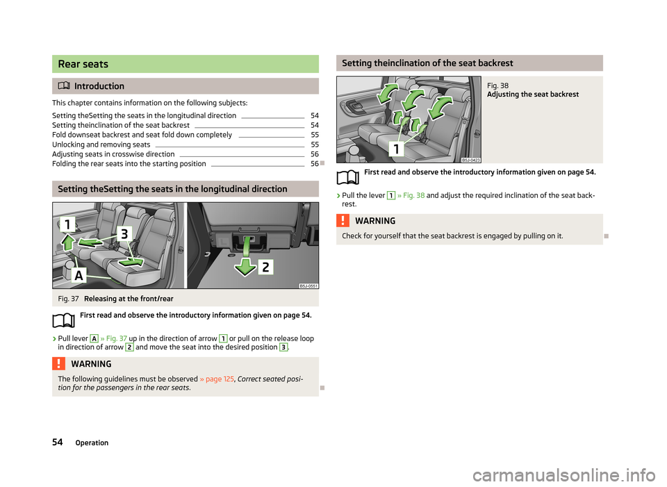
Fig. 37
Releasing at the front/rear
First read and observe the introductory information given on page 54.
›
Pull lever
A
» Fig. 37 up in the direction of arrow
1
or pull on the release loop
in direction of arrow
2
and move the seat into the desired position
3
.
WARNINGThe following guidelines must be observed » page 125, Correct seated posi-
tion for the passengers in the rear seats .
Setting theinclination of the seat backrestFig. 38
Adjusting the seat backrest
First read and observe the introductory information given on page 54.
›
Pull the lever
1
» Fig. 38 and adjust the required inclination of the seat back-
rest.
WARNINGCheck for yourself that the seat backrest is engaged by pulling on it.
54Operation
Page 58 of 219
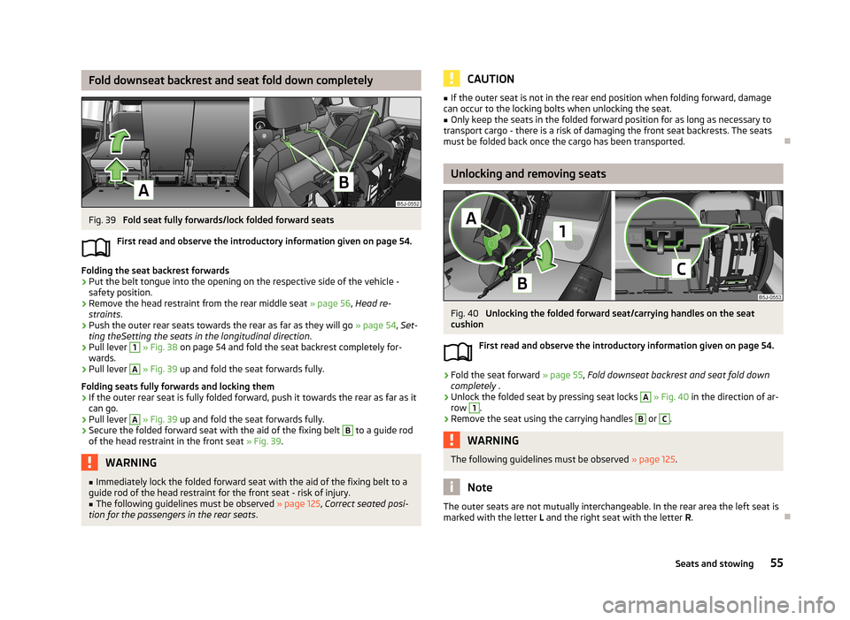
Fold downseat backrest and seat fold down completelyFig. 39
Fold seat fully forwards/lock folded forward seats
First read and observe the introductory information given on page 54.
Folding the seat backrest forwards
›
Put the belt tongue into the opening on the respective side of the vehicle -
safety position.
›
Remove the head restraint from the rear middle seat » page 56, Head re-
straints .
›
Push the outer rear seats towards the rear as far as they will go » page 54, Set-
ting theSetting the seats in the longitudinal direction .
›
Pull lever
1
» Fig. 38 on page 54 and fold the seat backrest completely for-
wards.
›
Pull lever
A
» Fig. 39 up and fold the seat forwards fully.
Folding seats fully forwards and locking them
›
If the outer rear seat is fully folded forward, push it towards the rear as far as it
can go.
›
Pull lever
A
» Fig. 39 up and fold the seat forwards fully.
›
Secure the folded forward seat with the aid of the fixing belt
B
to a guide rod
of the head restraint in the front seat » Fig. 39.
WARNING■
Immediately lock the folded forward seat with the aid of the fixing belt to a
guide rod of the head restraint for the front seat - risk of injury.■
The following guidelines must be observed » page 125, Correct seated posi-
tion for the passengers in the rear seats .CAUTION■
If the outer seat is not in the rear end position when folding forward, damage
can occur to the locking bolts when unlocking the seat.■
Only keep the seats in the folded forward position for as long as necessary to
transport cargo - there is a risk of damaging the front seat backrests. The seats must be folded back once the cargo has been transported.
Unlocking and removing seats
Fig. 40
Unlocking the folded forward seat/carrying handles on the seat
cushion
First read and observe the introductory information given on page 54.
›
Fold the seat forward » page 55, Fold downseat backrest and seat fold down
completely .
›
Unlock the folded seat by pressing seat locks
A
» Fig. 40 in the direction of ar-
row
1
.
›
Remove the seat using the carrying handles
B
or
C
.
WARNINGThe following guidelines must be observed » page 125.
Note
The outer seats are not mutually interchangeable. In the rear area the left seat is
marked with the letter L and the right seat with the letter R.
55Seats and stowing
Page 59 of 219

Adjusting seats in crosswise directionFig. 41
Locking seats
First read and observe the introductory information given on page 54.
›
Remove the middle seat » page 55, Unlocking and removing seats .
›
Fold the outer seat forwards » page 55, Fold downseat backrest and seat fold
down completely and unlock » Fig. 40 on page 55.
›
Move the folded forward and unlocked seat on the guide towards the middle of
the vehicle up to the stop.
›
Lock the folded seat by pressing seat locks
A
» Fig. 41 in the direction of the
arrow.
Folding the rear seats into the starting position
Fig. 42
Folding the seat backrest back
into positionFirst read and observe the introductory information given on page 54.›
If the seat has been removed, first position it on the guide and lock it in place » Fig. 41 on page 56. Pull the seat upwards to ensure that the seat is
locked correctly.
›
Fold the seat in the horizontal position until it can be heard to click. Check for yourself that the seat can no longer be lifted by pulling it up.
›
Press the lever » Fig. 42 and fold back the seat backrest. Check for yourself that
the seat backrest is engaged by pulling on it.
›
Remove the tongue of the lock from the safety position.
WARNING■ The belt locks must be in their original position after folding back the seat
cushions and backrests - they must be ready to use.■
The seat backrests must be securely latched in position so that no objects
from the luggage compartment can slip into the passenger compartment un-
der sudden braking – there is a risk of injury.
■
When folding the seat backrest always make sure that it has safely locked
into position, this is confirmed by the position and a visible marking on the
cover of the lever.
Head restraints
Introduction
This chapter contains information on the following subjects:
headrest adjust
57
Best protection is achieved if the top edge of the head restraint is at the same
level as the upper part of your head.
The head restraints must be adjusted to match the size of the seat occupant. Cor-
rectly adjusted head restraints together with the seat belts offer effective protec-
tion for the occupants » page 124.
56Operation
Page 60 of 219
WARNING■The head restraints must be correctly adjusted in order to offer effective
protection for the occupants in the event of an accident.■
Never drive with the head restraints removed - risk of injury.
■
If the rear seats are occupied, the rear head restraint must not be in the
lower position.
headrest adjust
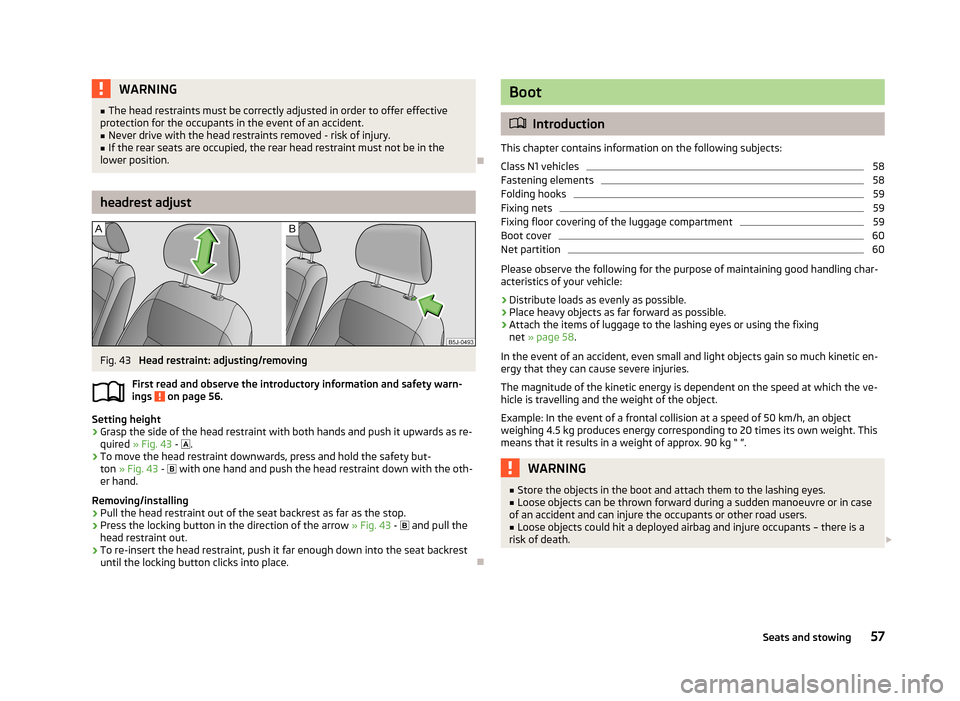
Fig. 43
Head restraint: adjusting/removing
First read and observe the introductory information and safety warn- ings
on page 56.
Setting height
›
Grasp the side of the head restraint with both hands and push it upwards as re-
quired » Fig. 43 -
.
›
To move the head restraint downwards, press and hold the safety but-
ton » Fig. 43 -
with one hand and push the head restraint down with the oth-
er hand.
Removing/installing
›
Pull the head restraint out of the seat backrest as far as the stop.
›
Press the locking button in the direction of the arrow » Fig. 43 -
and pull the
head restraint out.
›
To re-insert the head restraint, push it far enough down into the seat backrest until the locking button clicks into place.
Boot
Introduction
This chapter contains information on the following subjects:
Class N1 vehicles
58
Fastening elements
58
Folding hooks
59
Fixing nets
59
Fixing floor covering of the luggage compartment
59
Boot cover
60
Net partition
60
Please observe the following for the purpose of maintaining good handling char-
acteristics of your vehicle:
›
Distribute loads as evenly as possible.
›
Place heavy objects as far forward as possible.
›
Attach the items of luggage to the lashing eyes or using the fixing net » page 58 .
In the event of an accident, even small and light objects gain so much kinetic en-
ergy that they can cause severe injuries.
The magnitude of the kinetic energy is dependent on the speed at which the ve-
hicle is travelling and the weight of the object.
Example: In the event of a frontal collision at a speed of 50 km/h, an object
weighing 4.5 kg produces energy corresponding to 20 times its own weight. This
means that it results in a weight of approx. 90 kg “ ”.
WARNING■ Store the objects in the boot and attach them to the lashing eyes.■Loose objects can be thrown forward during a sudden manoeuvre or in case
of an accident and can injure the occupants or other road users.■
Loose objects could hit a deployed airbag and injure occupants – there is a
risk of death.
57Seats and stowing
Page 65 of 219
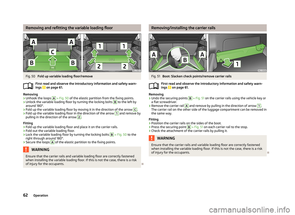
Removing and refitting the variable loading floorFig. 50
Fold up variable loading floor/remove
First read and observe the introductory information and safety warn- ings
on page 61.
Removing
›
Unhook the loops
A
» Fig. 50 of the elastic partition from the fixing points.
›
Unlock the variable loading floor by turning the locking bolts
B
to the left by
around 180°.
›
Fold up the variable loading floor by moving it in the direction of the arrow
C
.
›
Fold up the variable loading floor in the direction of the arrow
1
and remove by
pulling in the direction of the arrow
2
.
Fitting
›
Fold up the variable loading floor and place it on the carrier rails.
›
Fold out the variable loading floor.
›
Lock the variable loading floor by turning the locking bolts
B
» Fig. 50 to the
right through around 180°.
›
Secure the loops
A
of the elastic partition to the fixing points.
WARNINGEnsure that the carrier rails and variable loading floor are correctly fastened
when installing the variable loading floor. If this is not the case, there is a risk
of injury for the occupants.
Removing/installing the carrier railsFig. 51
Boot: Slacken check points/remove carrier rails
First read and observe the introductory information and safety warn-
ings
on page 61.
Removing
›
Undo the securing points
B
» Fig. 51 on the carrier rails using the vehicle key or
a flat screwdriver.
›
Remove the carrier rail
A
and remove by pulling in the direction of arrow
1
.
The carrier rail on the other side of the luggage compartment can be removed in
the same way.
Fitting
›
Position the carrier rails on the sides of the boot.
›
Press the securing point
B
» Fig. 51 on each carrier rail to the stop.
›
Check the attachment of the carrier rails by pulling it.
WARNINGEnsure that the carrier rails and variable loading floor are correctly fastened
when installing the variable loading floor. If this is not the case, there is a risk of injury for the occupants.
62Operation
Page 66 of 219
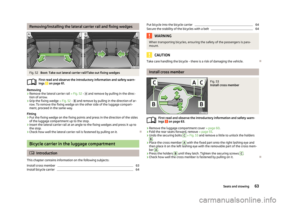
Removing/installing the lateral carrier rail and fixing wedgesFig. 52
Boot: Take out lateral carrier rail/Take out fixing wedges
First read and observe the introductory information and safety warn- ings
on page 61.
Removing
›
Remove the lateral carrier rail » Fig. 52 -
and remove by pulling in the direc-
tion of arrow.
›
Grip the fixing wedge » Fig. 52 -
and remove by pulling in the direction of ar-
row. To remove the fixing wedge on the other side of the luggage compart-
ment, proceed in the same way.
Fitting
›
Put the fixing wedge on the fixing points and press in the direction of the sides
of the luggage compartment up to the stop.
›
Insert the lateral carrier rail at an angle to the fixing wedges and press it up to
the stop.
›
Check how well the lateral carrier rail is fastened by pulling on it.
Bicycle carrier in the luggage compartment
Introduction
This chapter contains information on the following subjects:
Install cross member
63
Install bicycle carrier
64Put bicycle into the bicycle carrier64Secure the stability of the bicycles with a belt64WARNINGWhen transporting bicycles, ensuring the safety of the passengers is para-
mount.
CAUTION
Take care handling the bicycle - there is a risk of damaging the vehicle.
Install cross member
Fig. 53
Install cross member
First read and observe the introductory information and safety warn- ings on page 63.
›
Remove the luggage compartment cover » page 60.
›
Fold the rear seats forward, remove » page 55.
›
Undo the securing bolts
C
» Fig. 53 and remove a little to unlock the holders
B
.
›
Place the cross member
A
with the fixed part onto the right lashing eye and
then place it on the left lashing eye with the removable part of the cross mem-
ber
A
.
›
Press the holders
B
until they latch. Tighten the securing screws
C
.
›
Check how well the cross member is fastened by pulling on it.
63Seats and stowing
Page 68 of 219
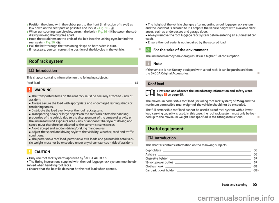
›Position the clamp with the rubber part to the front (in direction of travel) as
low down on the seat post as possible and lock it » Fig. 56 - .›
When transporting two bicycles, stretch the belt » Fig. 56 - between the sad-
dles by moving the bicycles apart.
›
Hook the carabiners on the ends of the belt into the lashing eyes behind the rear seats » Fig. 56 - .
›
Pull the belt through the tensioning clasps on both sides in turn.
›
If necessary, you can correct the position of the bicycles in the vehicle.
Roof rack system
Introduction
This chapter contains information on the following subjects:
Roof load
65WARNING■ The transported items on the roof rack must be securely attached – risk of
accident!■
Always secure the load with appropriate and undamaged lashing straps or
tensioning straps.
■
Distribute the load evenly over the roof rack system.
■
Transporting heavy or large objects on the roof rack alters the handling
properties of the vehicle due to the displacement of the centre of gravity or
the increased wind exposure area – risk of accident! The style of driving and
speed must therefore be adapted to the current circumstances.
■
Avoid abrupt and sudden driving/braking manoeuvres.
■
Adjust the speed and driving style to the visibility, weather, road and traffic
conditions.
■
The permissible roof load, permissible axle loads and permissible total vehi-
cle weight must not be exceeded under any circumstances – risk of accident!
CAUTION
■ Only use roof rack systems approved by ŠKODA AUTO a.s.■The fitting instructions supplied with the roof luggage rack system must be ob-
served when handling roof racks.■
Ensure that the boot lid does not hit the roof load when opened.
■ The height of the vehicle changes after mounting a roof luggage rack system
and the load that is secured to it. Compare the vehicle height with available clear- ances, such as underpasses and garage doors.■
Always remove the roof luggage rack system before entering an automated car
wash.
■
Ensure the roof aerial is not impaired by the secured load.
For the sake of the environment
The increased aerodynamic drag results in a higher fuel consumption.
Note
If the vehicle is not factory-equipped with a roof rack, it can be purchased from
the ŠKODA Original Accessories.
Roof load
First read and observe the introductory information and safety warn-
ings
on page 65.
The maximum permissible roof load (including roof rack system) of 75 kg and the
maximum permissible total weight of the vehicle should not be exceeded.
The full permissible roof load cannot be used if a roof rack system with a lower
load carrying capacity is used. In this case, the roof rack system must only be loa-
ded up to the maximum weight limit specified in the fitting instructions.
Useful equipment
Introduction
This chapter contains information on the following subjects:
Cupholders
66
Ashtray
66
Cigarette lighter
67
12-volt power outlet
67
Clothes hook
68
Car park ticket holder
68
65Seats and stowing