2013 SKODA ROOMSTER warning
[x] Cancel search: warningPage 118 of 219

START-STOP
Introduction
This chapter contains information on the following subjects:
Starting/shutting down the engine
115
Operating conditions for the system
115
Manually activating/deactivating the system
116
Information messages
116
The START-STOP system helps you to save fuel while at the same time reducing
harmful exhaust emissions and CO 2 emissions.
The function is automatically activated each time the ignition is switched on.
In the start-stop mode, the engine automatically switches to the vehicle's idle phase, e.g. when stopped at traffic lights. The engine restarts automatically
where necessary.
The system can work only if the following basic conditions are met. The driver's door is closed.
The driver has fastened the seat belt. The bonnet is closed.The driving speed exceeded 4 km/h after the last stop.
No trailer is coupled.
WARNING■ The brake servo unit and power steering only operate if the engine is run-
ning.■
Never let the vehicle roll with the engine switched off.
CAUTION
Always deactivate the START-STOP system before driving through wa-
ter » page 108 .Note■
If the driver's seat belt is removed for more than 30 seconds or the driver's door
is opened during stop mode, the engine will have to be started manually.■
After manually starting the engine, automatic engine shut down is not possible
until the vehicle has travelled the required minimum distance for START-STOP mode.
■
Changes to the outdoor temperature can have an effect on the internal temper-
ature of the vehicle battery even after several hours. If the vehicle remains out-
doors for a long time in minus temperatures or in direct sunlight, it can take sev-
eral hours until the internal temperature of the vehicle battery reaches a suitable
temperature for proper operation of the START STOP system.
■
If Climatronic is running in automatic mode, the engine may not switch off auto-
matically under certain conditions.
Starting/shutting down the engine
First read and observe the introductory information and safety warn-ings
on page 115.
›
Stop the vehicle (where necessary, apply the handbrake).
›
Shift the gear lever to Neutral.
›
Release the clutch pedal.
Automatic engine shut down (STOP phase) runs. The
warning symbol appears
in the instrument cluster display.
›
Depress the clutch pedal.
The new start procedure runs (START phase). The
warning symbol goes out.
Operating conditions for the system
First read and observe the introductory information and safety warn-
ings
on page 115.
The START-STOP system is very complex. Some of the procedures are hard to check without servicing.
No engine shut down runs
Before each STOP phase, the system checks whether certain conditions have
been met. No engine shut down runs in the following situations.
115Assist systems
Page 119 of 219
›The engine has not yet reached the minimum temperature for the START STOP
mode.
› The temperature inside the vehicle has not reached the desired temperature
set in the air-conditioning system/heating.
› The external temperature is very low/high.
› Intensive windscreen deicing (Climatronic) or windscreen deicing/ventilation is
switched on at the maximum air temperature setting (manual air conditioning
system).
› The parking aid is activated.
› The charge state of the vehicle battery is too low.
› The stationary vehicle is on a steep hill or a steep slope.
› The idling speed is too high.
› The steering angle is too great (manoeuvring).
The
warning symbol is being shown in the instrument cluster display.
The automatic start procedure runs again During the STOP phase, the engine fires up without any active driver intervention,
e.g. in the following situations.
› The vehicle has begun to roll, e.g. on a slope.
› The difference between the temperature setting of the air-conditioning sys-
tem/heating and the temperature of the interior is too great.
› Intensive windscreen deicing (Climatronic) or windscreen deicing/ventilation is
switched on at the maximum air temperature setting (manual air conditioning
system).
› The brake pedal was pressed several times (the pressure in the braking system
is too low).
› The charge state of the vehicle battery is too low.
› The current consumption is too high.
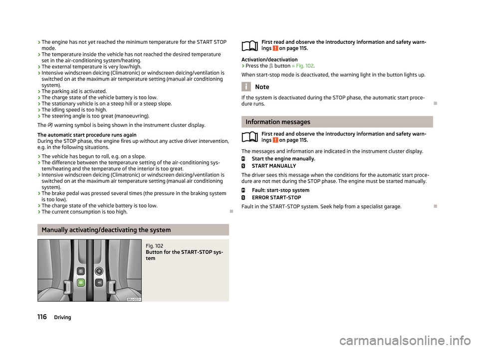
Manually activating/deactivating the system
Fig. 102
Button for the START-STOP sys-
tem
First read and observe the introductory information and safety warn-
ings on page 115.
Activation/deactivation
›
Press the button » Fig. 102 .
When start-stop mode is deactivated, the warning light in the button lights up.
Note
If the system is deactivated during the STOP phase, the automatic start proce-
dure runs.
Information messages
First read and observe the introductory information and safety warn-
ings
on page 115.
The messages and information are indicated in the instrument cluster display.
Start the engine manually.START MANUALLY
The driver sees this message when the conditions for the automatic start proce- dure are not met during the STOP phase. The engine must be started manually.
Fault: start-stop system
ERROR START-STOP
Fault in the START-STOP system. Seek help from a specialist garage.
116Driving
Page 120 of 219
Towing a trailer
Towing device
Introduction
This chapter contains information on the following subjects:
Description
117
Adjusting the ready position
118
Fitting the ball head
118
Check proper fitting
119
Removing the ball head
119
Use and care
120
If your vehicle has already been factory-fitted with towing equipment or is fitted
with towing equipment from ŠKODA Original Accessories, then it meets all of the technical requirements and national legal provisions for towing a trailer.
Your vehicle is fitted with a 13-pin power socket for the electrical connection be-tween the vehicle and trailer. If the trailer that is to be towed has a 7-pin connec-
tor , you can use a suitable adapter from ŠKODA Original Accessories.
The maximum trailer drawbar load is 50 kg/h.
WARNING■
Check that the ball head is seated correctly and is secured in the mounting
recess before starting any journey.■
Do not use the ball head if it is not correctly inserted in the mounting recess.
■
Do not use the towing equipment if it is damaged or incomplete.
■
Do not modify or adapt the towing equipment in any way.
■
Never release the ball head while the trailer is still coupled.
CAUTION
Take care with the ball head to avoid damaging the paintwork on the bumper.
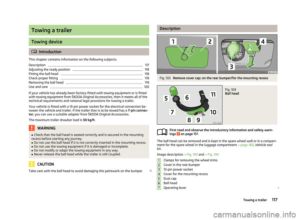
DescriptionFig. 103
Remove cover cap: on the rear bumper/for the mounting recess
Fig. 104
Ball head
First read and observe the introductory information and safety warn-
ings on page 117.
The ball head can be removed and is kept in the spare wheel well or in a compart- ment for the spare wheel in the luggage compartment » page 180, Vehicle tool
kit .
Image description » Fig. 103 and » Fig. 104
Clamps for removing the wheel trims
Cover in the rear bumper
13-pin power socket
Cover for the mounting recess
Dust cap
Ball head
Operating lever
1234567117Towing a trailer
Page 122 of 219
WARNING■Carefully remove the cap for the mounting recess - there is a risk of hand
injury.■
Keep your hands outside the lever's range of motion when attaching the ball
head – there is a risk of finger injury.
■
Never attempt to pull the operating lever upwards forcibly to turn the key.
Doing so would mean the ball head is not attached correctly.
CAUTION
■ After removing the key, always replace the cap on the lock of the operating lev-
er – there is a risk of dirt getting into the lock.■
Keep the mounting recess of the towing equipment clean at all times. Such dirt
prevents the ball head from being attached securely.
■
After removing the ball head, always place the cap on the mounting recess.
■
Remove the cover from the rear bumper with care - there is a risk of paint dam-
age to the bumper and the cap.
Note
Store cover 2 and cover 4 » Fig. 103 on page 117 in a suitable place in the lug-
gage compartment after removing them.
Check proper fitting
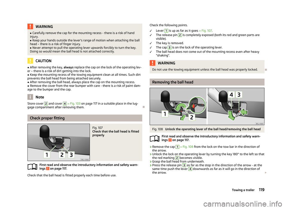
Fig. 107
Check that the ball head is fitted
properly
First read and observe the introductory information and safety warn-
ings on page 117.
Check that the ball head is fitted properly each time before use.
Check the following points.
Lever 1
is up as far as it goes » Fig. 107.
The release pin
2
is completely exposed (both its red and green parts are
visible).
The key is removed.
The cap
3
is on the lock of the operating lever.
The ball head does not come out of the mounting recess even after heavy
“shaking”.
WARNINGDo not use the towing equipment unless the ball head was properly locked.
Removing the ball head
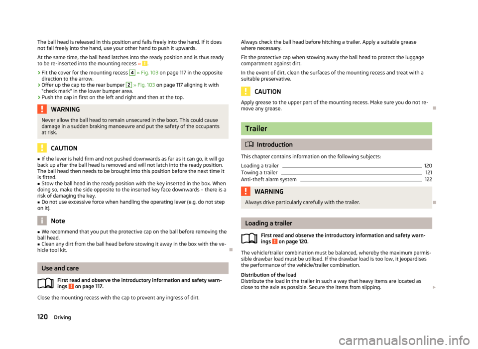
Fig. 108
Unlock the operating lever of the ball head/removing the ball head
First read and observe the introductory information and safety warn- ings
on page 117.
›
Remove the cap
1
» Fig. 108 from the lock on the tow bar in the direction of
the arrow.
›
Unlock the lock on the operating lever by turning the key 180° to the left so that
the red marking
2
becomes visible.
›
Grasp the ball head from underneath.
›
Press the release pin
3
as far as the stop in the direction of the arrow - at the
same time push the lever
4
downwards as far as it will go in the direction of
the arrow.
119Towing a trailer
Page 123 of 219
The ball head is released in this position and falls freely into the hand. If it does
not fall freely into the hand, use your other hand to push it upwards.
At the same time, the ball head latches into the ready position and is thus readyto be re-inserted into the mounting recess »
.
›
Fit the cover for the mounting recess
4
» Fig. 103 on page 117 in the opposite
direction to the arrow.
›
Offer up the cap to the rear bumper
2
» Fig. 103 on page 117 aligning it with
“check mark” in the lower bumper area.
›
Push the cap in first on the left and right and then at the top.
WARNINGNever allow the ball head to remain unsecured in the boot. This could cause damage in a sudden braking manoeuvre and put the safety of the occupantsat risk.
CAUTION
■ If the lever is held firm and not pushed downwards as far as it can go, it will go
back up after the ball head is removed and will not latch into the ready position.
The ball head then needs to be brought into this position before the next time it
is fitted.■
Stow the ball head in the ready position with the key inserted in the box. When
doing so, make the side opposite to the inserted key face downwards – there is a
risk of damaging the key.
■
Do not use excessive force when handling the operating lever (e.g. do not step
on it).
Note
■ We recommend that you put the protective cap on the ball before removing the
ball head.■
Clean any dirt from the ball head before stowing it away in the box with the ve-
hicle tool kit.
Use and care
First read and observe the introductory information and safety warn-
ings
on page 117.
Close the mounting recess with the cap to prevent any ingress of dirt.
Always check the ball head before hitching a trailer. Apply a suitable grease where necessary.
Fit the protective cap when stowing away the ball head to protect the luggage
compartment against dirt.
In the event of dirt, clean the surfaces of the mounting recess and treat with a
suitable preservative.
CAUTION
Apply grease to the upper part of the mounting recess. Make sure you do not re-
move any grease.
Trailer
Introduction
This chapter contains information on the following subjects:
Loading a trailer
120
Towing a trailer
121
Anti-theft alarm system
122WARNINGAlways drive particularly carefully with the trailer.
Loading a trailer
First read and observe the introductory information and safety warn-
ings
on page 120.
The vehicle/trailer combination must be balanced, whereby the maximum permis-
sible drawbar load must be utilised. If the drawbar load is too low, it jeopardises the performance of the vehicle/trailer combination.
Distribution of the load
Distribute the load in the trailer in such a way that heavy items are located as close to the axle as possible. Secure the items from slipping.
120Driving
Page 124 of 219

The distribution of the weight is very poor if your vehicle is unladen and the trail-
er is laden. Maintain a particularly low speed if you cannot avoid driving with this
combination.
Tyre pressure
Correct the tyre inflation pressure on your vehicle for a “full load” » page 173,
Service life of tyres .
Trailer load
The permissible trailer load must not be exceeded under any circumstan- ces » page 199 , Technical data .
The trailer loads specified apply only to altitudes up to 1 000 metres above mean
sea level.
The engine output falls as altitude increases, as does the ability to climb. There-
fore, for every additional 1000 m in height (or part), the maximum permissible
towed weight must be reduced by 10 %.
The towed weight comprises the actual weights of the (loaded) towing vehicleand the (loaded) trailer.
The trailer and drawbar load information on the type plate of the towing equip-
ment are merely test data for the towing equipment. The vehicle-specific values
are detailed in the vehicle documents.WARNING■ Do not exceed the maximum permissible axle and drawbar load and the
maximum permissible total or towed weight of the vehicle and the trailer –
there is the risk of an accident and serious injury.■
Slipping loads can significantly affect the stability and safety of the vehicle/
trailer combination – there is the risk of an accident and serious injury.
Towing a trailer
First read and observe the introductory information and safety warn-
ings
on page 120.
Exterior mirrors
You have to have additional exterior mirrors fitted if you are not able to see the
traffic behind the trailer with the standard rear-view mirrors. The national legal requirements must be observed.
Headlights
The front of the vehicle can be lifted when a trailer is being towed and the head- lights can dazzle other road users.
Adjust the headlight setting on the headlight range control » page 42, Headlight
beam adjustment .
Driving speed
For safety reasons, do not drive faster than 80 km/h when towing a trailer.
Immediately reduce your speed as soon as even the slightest swaying of the trail- er is detected. Never attempt to stop the trailer from “swaying” by accelerating.
Brakes
Apply the brakes in good time! If the trailer is fitted with a trailer brake, apply the
brakes gently at first, then brake firmly. This will avoid brake jolts resulting from
the trailer wheels locking.
On downhill sections shift down a gear in good time to also use the engine as a
brake.
Engine overheating
The speed must be reduced immediately if the needle for the coolant tempera-
ture gauge moves into the right-hand area or the red area of the scale.
Stop and switch off the engine if the warning light
in the instrument cluster
starts to flash. Wait a few minutes and check the level of coolant » page 166,
Checking the coolant level .
The following guidelines must be observed » page 22,
Coolant .
The coolant temperature can be reduced by switching on the heating.WARNING■ Adapt your speed to the conditions of the road surface and to the traffic sit-
uation.■
Improper or incorrectly connected electric cables can energise the trailer and
cause functional faults to the vehicle's entire electrical system as well as acci-
dents and severe injuries.
■
Work on the electrical system must only be carried out by specialist garages.
■
Never directly connect the trailer's electrical system with the electrical con-
nections for the tail lights or other current sources.
121Towing a trailer
Page 126 of 219
Safety
Passive Safety
General information
Introduction
This chapter contains information on the following subjects:
Safety equipment
123
Before setting off
123
What influences the driving safety?
124
In this section you will find important information, tips and notes on the subject
of passive safety in your vehicle.
We have combined everything here which you should be familiar with, for exam- ple, regarding seat belts, airbags, child seats and safety of children.
WARNING■ This chapter contains important information on how to use the vehicle for
the driver and his occupants.■
You can find further information on safety concerning you and those travel-
ling with you in the following chapters of this owner's manual.
■
The complete on-board literature should always be in the vehicle. This ap-
plies in particular, if you rent out or sell the vehicle.
Safety equipment
First read and observe the introductory information and safety warn-ings
on page 123.
The following list contains only part of the safety equipment in your vehicle.
› Three-point seat belts for all the seats.
› Belt force limiters for the front seats.
› Belt tensioners for the front seats.
› Seat belt height adjusters for the front seats.
›
Front airbag for the driver and the front passenger.
› Side airbags.
› Head airbags.
› Anchoring points for child seats using the ISOFIX system.
› Anchoring points for child seats using the TOP TETHER system.
› Head restraints adjustable for height.
› Adjustable steering column.
The specified safety equipment works together, in order to optimally protect you
and those travelling with you in accident situations.
The safety equipment does not protect you or the people travelling with you, if
you or your occupants adopt an incorrect seated position or the equipment is not
correctly adjusted or used.
If the seat belt is not fastened properly, this may result in injuries if an airbag is
activated in the event of an accident.
Before setting off
First read and observe the introductory information and safety warn-
ings
on page 123.
For your own safety and the safety of the people travelling with you, please pay
attention to the following points before setting off.
› Ensure that the lighting and the turn signal system are functioning properly.
› Check the tyre inflation pressure.
› Ensure that all of the windows offer good visibility to the outside.
› Secure all items of luggage
» page 57.
› Ensure that no objects can obstruct the pedals.
› Adjust the mirrors, the front seat and head restraint to your body size.
› Advise your passengers to adjust the head restraints to their body size.
› Protect children in suitable child seats with correctly fastened seat
belts » page 139 , Transporting children safely .
› Adopt the correct seated position
» page 124. Tell your passengers to assume
the correct seated position.
› Correctly fasten the seat belt. Also inform passengers to fasten the seat belt
correctly » page 127 , Using seat belts .
123Passive Safety
Page 127 of 219

What influences the driving safety?First read and observe the introductory information and safety warn-ings
on page 123.
The driver is fully responsible for himself and his occupants. If your driving safety is effected, you place yourself and the oncoming traffic at risk.
The following guidelines must therefore be observed. › Do not become distracted from concentrating on the traffic situation, e.g. by
your passengers or mobile phone calls.
› Never drive when your driving ability is impaired, e.g. due to medication, alcohol
or drugs.
› Keep to the traffic regulations and the permissible speed limit.
› Always adjust the driving speed to the road, traffic and weather conditions.
› Take regular breaks on long journeys – at least every two hours.
Correct seated position
Introduction
This chapter contains information on the following subjects:
Correct seated position for the driver
125
Correct seated position for the front passenger
125
Correct seated position for the passengers in the rear seats
125
Examples of incorrect seated positions
125WARNINGGeneral information■The front seats and head restraints must be adjusted to match the body
size at all times and the seat belt must always be fastened properly to provide the most effective levels of protection to the passengers.■
If the occupant adopts an incorrect seated position, he is exposed to life-
threatening injuries, in case he is hit by a deployed airbag.
■
If the occupants on the rear seats are not sitting upright, the risk of injury is
increased due to incorrect routing of the seat belt.
■
The seat backrests must not be tilted too far back when driving, as this will
impair the function of the seat belts and of the airbag system – risk of injury!
WARNINGInformation for the driver■Always assume the correct seated position before setting off and do not
change this position while driving. Also advise your passengers to adopt the
correct seated position and not to change this position while the car is mov-
ing.■
Maintain a distance of at least 25 cm to the steering wheel. Not maintaining
this minimum distance will mean that the airbag system will not be able to
properly protect you - hazard!
■
When driving, hold the steering wheel with both hands firmly on the outer
edge in the 9 o'clock and 3 o'clock position. Never hold the steering wheel in
the 12 o'clock position or in any other way (e.g. in the middle or inner edge of
the steering wheel). In such cases, you could severely injure the arms, hands
and head when the driver airbag is deployed.
■
Ensure that there are no objects in the driver's footwell, as these may get
caught in the pedal apparatus when driving or braking. You would then no longer be able to operate the clutch, brake or acceleration pedals.
WARNINGInformation for the front seat passenger■Maintain a distance of at least 25 cm from the dash panel. Not maintaining
this minimum distance will mean that the airbag system will not be able to
properly protect you - there is a risk that you could be killed.■
Always keep your feet in the footwell when the car is being driven - never
place your feet on the instrument panel, out of the window or on the seats.
You will be exposed to increased risk of injury if it becomes necessary to apply
the brakes or in the event of an accident. You may suffer fatal injuries when
an airbag is deployed if you have adopted an incorrect seating position.
124Safety