Page 169 of 193

›Switch off the ignition and all of the lights before replacing a bulb.
› Faulty bulbs must only be replaced with the same type of bulbs. The designa-
tion is located on the light socket or the glass bulb.
› A stowage compartment for replacement bulbs is located in a plastic box in
the spare wheel or underneath the floor covering in the boot.WARNING■ Always read and observe the warning notes before completing any work
in the engine compartment » page 131, Engine compartment .■
Accidents can be caused if the road in front of the vehicle is not suffi-
ciently illuminated and the vehicle cannot be seen or can only be seen with
difficulty by other road users.
■
H7 and H15 bulbs are pressurised and may burst when changing the bulb -
risk of injury! We therefore recommended wearing gloves and safety
glasses when changing a bulb.
■
Gas discharge bulbs (xenon bulbs) operate with a high voltage, professio-
nal knowledge is required – risk of death!
■
Switch off the respective vehicle light when changing the bulb.
CAUTION
Do not take hold of the glass bulb with naked fingers (even the smallest
amount of dirt reduces the working life of the light bulb). Use a clean cloth,
napkin, or similar.
Note
■ This Owner's Manual only describes the replacement of bulbs where it is pos-
sible to replace the bulbs on your own without any complications arising. Other
bulbs must be replaced by a specialist garage.■
We recommend that a box of replacement bulbs always be carried in the ve-
hicle. Replacement bulbs can be purchased from ŠKODAOriginal Accessories.
■
We recommend having the headlight settings checked by a specialist garage
after replacing a bulb in the main, low or fog beam.
■
In case of failure of a xenon gas discharge lamp or an LED diode, visit a spe-
cialist garage.
Bulb arrangement in the headlightsFig. 159
Principle sketch: Headlights
Read and observe and on page 167 first.
Bulb arrangement » Fig. 159
Low beam » page 167 or low beam with xenon gas discharge lamp
Main beam, separate daytime running lights, and parking light » page 168
Turn signal light (at the front) » page 168
Replacing the low beam bulb
Fig. 160
Headlight with halogen bulb:
Bulb for low beam
Read and observe and on page 167 first.
›
Remove the protective cap
A
» Fig. 159 on page 167 .
›
Remove the connector with the bulb by jiggling it out in the direction of the
arrow » Fig. 160 .
›
Remove the connector.
›
Insert a new light bulb in such a way that the fixing lugs of the bulb fit in the
recesses of the reflector.
›
Attach the connector.
›
Fit the protective cap
A
» Fig. 159 on page 167 .
ABC167Fuses and light bulbs
Page 170 of 193

Replacing bulb for main beam, daytime running lights and parking
lightFig. 161
Bulbs for main beam, daytime running lights, and parking light
Read and observe
and on page 167 first.
Removing/replacing the bulb for main beam and separate daytime running
lights
›
Remove the protective cap
B
» Fig. 159 on page 167 .
›
Turn the bulb holder
A
» Fig. 161 as far as it goes in the direction of the ar-
row and remove it.
›
Replace the bulb, insert the bulb holder with the new bulb and turn in the
opposite direction to that of the arrow as far as it goes.
›
Fit protective cap
B
» Fig. 159 on page 167 Insert.
Removing/replacing the bulb for the parking light
›
Remove the protective cap
B
» Fig. 159 on page 167 .
›
Remove the bulb holder with the bulb by jiggling it out in the direction of the
arrow
1
» Fig. 161 .
›
Remove the faulty bulb from the holder in the direction of the arrow
2
.
›
Insert a new bulb in the bulb holder up to the stop.
›
Replace the bulb holder in the headlamp with the bulb.
›
Fit protective cap
B
» Fig. 159 on page 167 Insert.
Changing the front turn signal bulbFig. 162
Principle sketch: Bulb for indica-
tor
Read and observe and on page 167 first.
›
Turn the socket with the bulb » Fig. 162 as far as it will go in the direction of
the arrow and then remove it.
›
Remove the bulb, insert the new bulb into the socket and turn in the oppo-
site direction to that of the arrow to the stop.
Replacing the bulb for the fog light
Fig. 163
Front bumper: Protective grille/removing the fog light
168Do-it-yourself
Page 171 of 193

Fig. 164
Replacing the light bulb
Read and observe and on page 167 first.
Removing the protective grille
›
Undo the protective grille in the area of the arrow » Fig. 163 -
using the
clamp for removing the wheel trims » page 150, Vehicle tool kit .
›
Remove the protective grille in the direction of the arrow
1
» Fig. 163 .
Changing light bulbs for fog lights
›
Unscrew the screws » Fig. 163 -
marked with the arrows 1)
.
›
Unlock the fuse in the direction of the arrow
2
with the screwdriver.
›
Remove the headlight in the direction of arrow
3
.
›
Remove the connector » Fig. 164.
›
Turn the lamp socket in the direction of arrow
4
» Fig. 164 and pull it out.
›
Insert the bulb holder with the new bulb into the headlight and turn counter
to the direction of arrow
4
.
›
Attach the connector.
›
Replace the fog light by inserting it in the opposite direction of the arrow
3
» Fig. 163 and tighten.
›
Insert the protective grille and carefully press it in.
The protective grille must engage firmly.
Replacing the bulb for the licence plate lightFig. 165
Remove the number plate light/replace the bulb
Read and observe
and on page 167 first.
›
Open the boot lid.
›
Push in the lamp in the direction of the arrow
1
» Fig. 165 .
The lamp comes loose.
›
Swivel out the lamp in the direction of the arrow
2
and remove it.
›
Remove the faulty bulb from the holder in the direction of the arrow
3
.
›
Insert a new bulb into the holder.
›
Reinsert the lamp in the opposite direction to the arrow
1
.
›
Push on the light until the spring clicks into place.
Check that the light is securely inserted.
1)
The screwdriver is part of the tool kit.
169Fuses and light bulbs
Page 172 of 193

Rear lampFig. 166
Remove cover/light
Fig. 167
Installing the lamp connector/lamp
Read and observe
and on page 167 first.
Removing
›
Open the boot lid.
›
Insert the clamp for removing the wheel trims » page 150, Vehicle tool kit
into the hole at the position indicated by the arrow » Fig. 166 -
.
›
Remove the cover in the direction of the arrow
1
-
» Fig. 166 .
›
Use the screwdriver from the tool kit to unscrew the lamp » Fig. 166 -
.
›
Grasp the light and carefully remove with shaky movements in the direction
of arrow
2
.
›
Carefully remove the connector from the tail lamp » Fig. 167 -
.
Installing
›
Insert the connector into the lamp and lock it securely.
›
Insert the lamp into the mounts in the body » Fig. 167 -
.
›Carefully press the tail lamp into the body so that the bolts 2
» Fig. 168 on
page 170 on the lamp engage into the mounts in the body » .
Ensure that the cable bundle does not become pinched between the body and
the lamp.›
Screw the tail lamp into place and install the cover.
The cover must engage securely.
CAUTION
■ Ensure that the cable bundle does not become pinched between the body
and the lamp when it is being refitted – risk of damage to the electrical instal-
lation and risk of water ingress.■
If you are not sure whether the cable bundle has become pinched, we recom-
mend that you have the light connection checked by a specialist garage.
■
Ensure that the vehicle paintwork and the tail lamp are not damaged when
removing and installing the tail lamp.
Replacing bulbs in rear light
Fig. 168
Outer part of the lamp/inner part of the lamp
Read and observe
and on page 167 first.
Outer part of the lamp
›
Turn the bulb holder
1
» Fig. 168 in an anti-clockwise direction and remove
it from the lamp housing.
›
Replace the bulb, reinsert the holder with the bulb into the lamp housing and
turn to the stop in a clockwise direction.
Inner parts of the lamp
›
Unlock the bulb holder using the locking latches marked with ar-
rows » Fig. 168 -
and remove the bulb holder from the tail lamp.
170Do-it-yourself
Page 173 of 193
›Turn the respective bulb
» Fig. 168 until it stops counter-clockwise and re-
move it from the bulb holder.›
Insert a new bulb into the holder and turn in a clockwise direction to the
stop.
›
Insert guide mandrels
3
» Fig. 168 of the bulb holder into the lamp.
All locking mechanisms must audibly snap into place.
171Fuses and light bulbs
Page 174 of 193

Technical data
Technical data
Vehicle data
Introduction
This chapter contains information on the following subjects:
Vehicle characteristics
172
Operating weight and payload
172
Measurement of fuel consumption and CO 2 emissions according to ECE
Regulations and EU Directives
173
Dimensions
174
Angle
175
Vehicle-specific details per engine type
176
The details given in the vehicle's technical documentation always take prece-
dence over the details in the Owner's Manual.
The listed performance values were determined without performance-reduc- ing equipment, e.g. air conditioning system.
Vehicle characteristics
Fig. 169
Vehicle data sticker/type plate
Vehicle data sticker
The vehicle data sticker » Fig. 169 -
is located on the base of the luggage
compartment and is also stuck into the service schedule.
The vehicle data sticker contains the following data.
Vehicle identification number (VIN)
Vehicle type
Gearbox code/paint number/interior equipment/engine output/engine
code
Partial vehicle description
Type plate
The type plate » Fig. 169 -
is located at the bottom of the B-pillar on the
driver's side.
The type plate contains the following data. Vehicle identification number (VIN)
Maximum permissible gross weight
Maximum permissible towed weight (towing vehicle and trailer)
Maximum permissible front axle load
Maximum permissible rear axle load
Vehicle identification number (VIN)
The vehicle identification number - VIN (vehicle body number) is stamped into
the engine compartment on the right hand suspension strut dome. This num-
ber is also located on a sign on the lower left hand edge below the windscreen
(together with a VIN bar code), and on the type plate.
Engine number
The engine number (three-digit identifier and serial number) is stamped on the engine block.WARNINGDo not exceed the specified maximum permissible weights – risk of acci-
dent and damage!
Operating weight and payload
Operating weight
This value represents the minimum operating weight without additional
weight-increasing equipment such as air conditioning system, spare wheel, or
trailer hitch.
The specified operating weight is for orientation purposes only.
123456789172Technical data
Page 175 of 193
, the weight
of the operating fluids, the tool kit, and a fuel tank filled to 90 % capacity.
Operating weight of the vehicle » page")
The operating weight also contains the weight of the driver (75 kg), the weight
of the operating fluids, the tool kit, and a fuel tank filled to 90 % capacity.
Operating weight of the vehicle » page 176, Vehicle-specific details per engine
type .
Payload
It is possible to calculate the approximate maximum payload from the differ-
ence between the permissible total weight and the operating weight.
The payload consists of the following weights.
› The weight of the passengers.
› The weight of all items of luggage and other loads.
› The weight of the roof, including the roof rack system.
› The weight of the equipment that is excluded from the operating weight.
› Trailer drawbar load when towing a trailer (max. 50 kg).
Note
If required, you can find out the precise weight of your vehicle at a specialist
garage.
Measurement of fuel consumption and CO 2 emissions according to
ECE Regulations and EU Directives
The data on fuel consumption and CO 2 emissions were not available at the
time of going to press.
The data on fuel consumption and CO 2 emissions are given on the ŠKODA
websites or in the sales and technical vehicle documentation.
The measurement of the intra-urban cycle begins with a cold start of the en-
gine. Afterwards urban driving is simulated.
In the extra-urban driving cycle, the vehicle is accelerated and decelerated in
all gears, corresponding to daily routine driving conditions. The driving speed
varies between 0 and 120 km/h.
The calculation of the combined fuel consumption considers a weighting of
about 37 % for the intra-urban cycle and 63 % for the extra-urban cycle.
Note■ The fuel consumption and emission levels given on the ŠKODA websites or in
the commercial and technical vehicle documentation have been established in
accordance with rules and under conditions that are set out by legal or techni-
cal rules for the determination of operational and technical data of motor vehi-
cles.■
Depending on the extent of the equipment, the driving style, traffic condi-
tions, weather influences and vehicle condition, consumption values can in
practice result in fuel economy figures in the use of the vehicle that differ from
the fuel consumption values listed on the ŠKODA websites or in the commer-
cial and technical vehicle documentation.
173Technical data
Page 176 of 193
DimensionsFig. 170
Principle sketch: Vehicle dimensions
Vehicle dimensions (mm)
» Fig. 170SpecificationValueAHeightBasic dimension1459/1471 a)Vehicles with a rough road package.1472/1484 a)B
Front track
Basic dimension1457For vehicles fitted with the 1.2 l/55 kW MPI and 1.2 l/63 kW TSI engines and 14"
wheel rims.1463CWidth1706D
Rear track
Basic dimension1494For vehicles fitted with the 1.2 l/55 kW MPI and 1.2 l/63 kW TSI engines and 14"
wheel rims.1500EWidth including exterior mirror1940FClearanceBasic dimension134Vehicles with a rough road package.141GWheel base2602HLength4304a)
Valid for vehicles with the Amundsen+ navigation system.
174Technical data
 1
1 2
2 3
3 4
4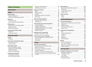 5
5 6
6 7
7 8
8 9
9 10
10 11
11 12
12 13
13 14
14 15
15 16
16 17
17 18
18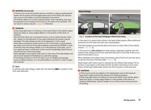 19
19 20
20 21
21 22
22 23
23 24
24 25
25 26
26 27
27 28
28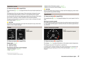 29
29 30
30 31
31 32
32 33
33 34
34 35
35 36
36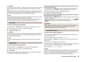 37
37 38
38 39
39 40
40 41
41 42
42 43
43 44
44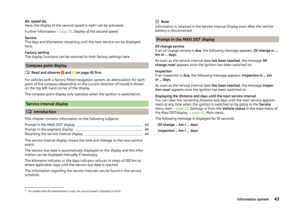 45
45 46
46 47
47 48
48 49
49 50
50 51
51 52
52 53
53 54
54 55
55 56
56 57
57 58
58 59
59 60
60 61
61 62
62 63
63 64
64 65
65 66
66 67
67 68
68 69
69 70
70 71
71 72
72 73
73 74
74 75
75 76
76 77
77 78
78 79
79 80
80 81
81 82
82 83
83 84
84 85
85 86
86 87
87 88
88 89
89 90
90 91
91 92
92 93
93 94
94 95
95 96
96 97
97 98
98 99
99 100
100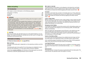 101
101 102
102 103
103 104
104 105
105 106
106 107
107 108
108 109
109 110
110 111
111 112
112 113
113 114
114 115
115 116
116 117
117 118
118 119
119 120
120 121
121 122
122 123
123 124
124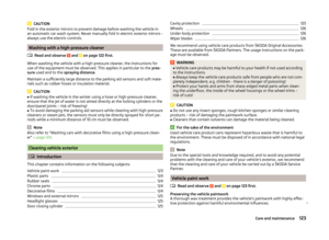 125
125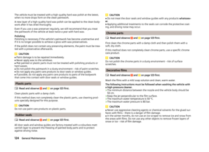 126
126 127
127 128
128 129
129 130
130 131
131 132
132 133
133 134
134 135
135 136
136 137
137 138
138 139
139 140
140 141
141 142
142 143
143 144
144 145
145 146
146 147
147 148
148 149
149 150
150 151
151 152
152 153
153 154
154 155
155 156
156 157
157 158
158 159
159 160
160 161
161 162
162 163
163 164
164 165
165 166
166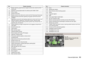 167
167 168
168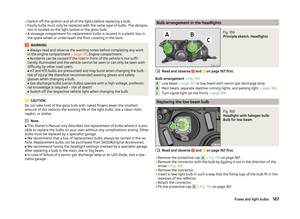 169
169 170
170 171
171 172
172 173
173 174
174 175
175 176
176 177
177 178
178 179
179 180
180 181
181 182
182 183
183 184
184 185
185 186
186 187
187 188
188 189
189 190
190 191
191 192
192

» Fig. 170SpecificationValueAHeightBasic dimension1459/1471 a)Vehicles with a rough road package.1472/1484 a)B
Front t")