Page 145 of 193
■You must have your tyres replaced with new ones at the latest when the
wear indicators have been worn down.■
Worn tyres impair necessary adhesion to the road surface, particula")
WARNING (Continued)■You must have your tyres replaced with new ones at the latest when the
wear indicators have been worn down.■
Worn tyres impair necessary adhesion to the road surface, particularly at
high speeds on wet roads. This could lead to “aquaplaning” (uncontrolled
vehicle movement – “swimming” on a wet road surface).
CAUTION
■ Protect the tyres from contact with oil, grease and fuel.■Replace lost valve caps.■
If, in the event of a puncture, it is necessary to fit a spare wheel with a tyre
without a dedicated running direction or with the opposite direction of rota-
tion, drive carefully as the optimal characteristics of the tyre are no longer ap-
plicable in this situation.
For the sake of the environment
Tyres that are insufficiently inflated increase your fuel consumption.
Note
■ We recommend that any works on the wheels or tyres be carried out by a
specialist garage.■
We recommend that you use wheel rims, tyres, full wheel trims and snow
chains from ŠKODA Original Accessories.
Service life of tyres
Fig. 130
Principle illustration: Replace tyre tread with wear indicators /
wheels
Fig. 131
Open the fuel filler flap with a table of tyre sizes and tyre pres-
sures / inflate tyres
Read and observe
and on page 142 first.
The service life of tyres depends on the inflation pressure, driving style and
other circumstances.
Sticker with prescribed tyre inflation pressure values » Fig. 131
Position of the CNG label
Standard filling for half load
Comfort inflation pressure for half load 1)
Standard filling pressure for a full load
Following the advice below can extend the service life of your tyres.
Tyre pressure
Check the tyre pressure, including that of the spare wheel, at least once a
month and also before setting off on a long journey.
The sticker with prescribed tyre inflation filling values is located on the inside
of the tank flap
A
» Fig. 131 .
In some vehicles, the tyre pressure can be adjusted to the comfort inflation
pressure value » Fig. 131
C
and a higher driving comfort can therefore be ach-
ieved.
With comfort inflation pressure, the fuel consumption can rise slightly.
The tyre pressure should be at the highest pressure specified for your vehicle
at all times.
ABCD1)
Valid for some vehicles.
143Wheels
Page 146 of 193

Always check the inflation pressure when the tyres are cold. Do not reduce the
higher pressure on warm tyres.
With greater additional load, adjust the tyre inflation pressure accordingly.
Driving style
Fast cornering, sharp acceleration and braking increase the wear of your tyres.
Balancing wheels
The wheels of a new vehicle are balanced. When driving, however, there are a
range of factors that may result in an imbalance. This may become apparent by
a “vibration” in the steering.
Have the wheels re-balanced after replacing the tyres.
Wheel alignment errors
Incorrect wheel alignment at the front or rear leads to excess wear of the
tyres.
Tyre damage
Drive over kerbs and other such obstacles slowly and at right angles wherever
possible in order to avoid damage to tyres and wheel trims.
We recommend checking your tyres and wheel rims for damage (punctures,
cuts, splits and bulges, etc.) on a regular basis. Remove foreign bodies (e.g.
small stones) from the tyre tread immediately.
Replacing wheels
If significantly greater wear is present on the front tyres, we recommend
swapping the front wheels with the rear wheels as shown in the dia-
gram » Fig. 130 -
. You will then obtain approximately the same life for all the
tyres.
We recommend that you swap the tyres every 10,000 km in order to achieve
even wear on all tyres and to ensure optimal service life for the tyres.
Storing tyres
Identify disassembled tyres so that the previous direction of rotation can be maintained if the tyres are reassembled.
Always store wheels or tyres in a cool, dry place that is as dark as possible.
Tyres which are not fixed to a wheel trim should be stored upright.Wear indicators
The base of the tread of the tyres has 1.6 mm high wear indicators installed.
These wear indicators are evenly spaced around the circumference of the tyre,
depending on the make » Fig. 130-
. Markings on the walls of the tyres
through the letters “TWI”, triangular symbols or other symbols identify the po-
sition of the wear indicators.
Tyre age
Tyres age and lose their original characteristics, even if they are not being
used. Therefore, we recommend not using summer or winter tyres older than 6
or 4 years old respectively.
New tyres
Read and observe
and on page 142 first.
Only use radial tyres of the same type, size (rolling circumference) and tread
pattern on one axle on all four wheels.
The tyre/wheel combinations which are approved for your vehicle are indica-
ted in your vehicle documents.
Where possible, replace tyres by axle. Always fit the tyres with the deeper
tread depth to the front wheels.
Explanation of tyre markings
195/55 R 15 85 H
What this means is:
195Tyre width in mm » Fig. 131 on page 14365Height/width ratio in % » Fig. 131 on page 143RCode letter for the type of tyre – Radial » Fig. 131 on page 14315Diameter of wheel in inches » Fig. 131 on page 14385Load index » HSpeed symbol »
The date of manufacture is stated on the tyre wall (possibly on the inside). e.g.
DOT ... 11 14...
means, for example, that the tyre was manufactured in the week 11 of 2014.
144General Maintenance
Page 147 of 193
487500515530545615630650690
Speed symbol
The maximum speed symbol indi")
Load index
The load index indicates the maximum permissible load for each individual
tyre.Load index838485868791929395Load
(In kg)487500515530545615630650690
Speed symbol
The maximum speed symbol indicates the maximum permissible vehicle speed
with fitted tyres in each category.
Speed iconRSTUHVWMaximum speed
(in km/h)170180190200210240270
CAUTION
The information about the load index and the speed symbol is listed in your
vehicle documents.
Unidirectional tyres
Read and observe
and on page 142 first.
The direction of rotation of the tyres is marked by arrows on the wall of the
tyre .
The indicated direction of rotation must be adhered to in order to ensure the
optimal characteristics of these tyres.
These characteristics mainly relate to the following.
› Increased driving stability.
› Reduced risk of aquaplaning.
› Reduced tyre noise and tyre wear.
Tyre control display
Introduction
This chapter contains information on the following subjects:
Setting
146
Display
146
Monitors the tyre pressure display and warns of a change in tyre pressure.
The system must be calibrated if one of the following is evident. › Change of tyre inflation pressure.
› Change one or more wheels.
› Change in position of a wheel on the vehicle.
› The warning light comes on while driving.
WARNINGInformation on tyre pressure■The tyre control display does not absolve the driver of the responsibility
to ensure the correct tyre inflation pressure. Check the tyre inflation pres-
sure at regular intervals.■
Too low or too high inflation pressure impairs handling.
■
If the inflation pressure is too low, the tyre will have to overcome a higher
rolling resistance. This will cause a significant increase in the temperature
of the tyre, especially at higher speeds. This can result in tread separation
and a tyre blow out.
■
The system cannot warn in case of very rapid tyre inflation pressure loss,
e.g. in case of sudden tyre damage. In this case, carefully bring the vehicle
to a standstill without sudden steering movements or sharp braking.
CAUTION
■ To ensure a proper functioning of the tyre control display, it is necessary to
repeat the basic setting every 10,000 km or once a year.■
The tyre pressure monitor does not replace the need to check tyre pressure
regularly.
145Wheels
Page 148 of 193

SettingFig. 132
Button for setting the tyre infla-
tion pressure control value
Read and observe and on page 145 first.
›
Inflate all of the tyres to the specified inflation pressure » page 143.
›
Switch on the ignition.
›
Press the symbol button
» Fig. 132 for longer than 2 seconds.
If the warning light in the instrument cluster lights up and does not go out
after the system configuration, this indicates a system fault.
If there is a blinking light in the instrument cluster, then there is a system
fault.
Display
Read and observe
and on page 145 first.
The control light in the instrument cluster lights up when any of the follow-
ing conditions are met.
› The tyre inflation pressure is low.
› The structure of the tyre is damaged.
› The vehicle is loaded on one side.
› The wheels of one axle are loaded more heavily (e.g. when towing a trailer or
when driving uphill or downhill).
› Snow chains are mounted.
› The spare wheel is mounted.
› One wheel per axle was changed.
WARNING■
When illuminated control lights light up in the instrument cluster lights,
immediately reduce speed and avoid violent steering and brake manoeu-
vres. Stop the vehicle as soon as possible and inspect the tyres and their
inflation pressure.■
Under certain circumstances (e.g. sporty style of driving, wintry or un-
paved roads) the warning light
in the instrument cluster may be delayed
or not light up at all.
Reserve and temporary spare wheel
Introduction
This chapter contains information on the following subjects:
Change
147
Spare wheel
147
Fit a wheel in the appropriate dimensions and design as soon as possible.
WARNING■ If, in the event of a puncture, it is necessary to fit a spare wheel with a
tyre without a dedicated running direction or with the opposite direction of
rotation, drive carefully as the optimal characteristics of the tyre are no lon-
ger applicable in this situation.■
If the dimensions or design of the spare wheel differ from the tyres fitted
to the vehicle (e.g. winter tyres or low-profile tyres), it must only be used
briefly in the event of a puncture and if an appropriately cautious style of
driving is adopted.
146General Maintenance
Page 149 of 193

ChangeFig. 133
Fixing the spare or temporary
spare wheel
Read and observe on page 146 first.
The spare or temporary spare wheel is located in a well under the floor cover-
ing in the boot and is fixed in place with a special bolt » Fig. 133.
Take out the wheel
›
Open the boot lid.
›
Lift up the floor in the luggage compartment.
›
Remove the box with the tool kit.
›
Unscrew the nut » Fig. 133anti-clockwise.
›
Take out the wheel.
Stow the wheel
›
Place the wheel into the spare wheel well with the wheel rim pointing down-
ward.
›
Screw the nut » Fig. 133clockwise until the wheel is safely secured.
›
Place the box with the tool kit back into the spare wheel and secure it with
the tape.
›
Fold back the floor in the luggage compartment.
›
Close the boot lid.
Spare wheel
Read and observe
on page 146 first.
A warning label is displayed on the rim of the temporary spare wheel.
Please note the following if you intend to use the temporary spare wheel. › The warning label must not be covered after installing the wheel.
› Be particularly observant when driving.
› The temporary spare wheel is inflated to the maximum inflation pressure for
the vehicle » Fig. 130 on page 143 .
› Only use this temporary spare wheel to reach the nearest specialist garage,
as it is not intended for long-term use.WARNING■ Never drive with more than one temporary spare wheel mounted!■Only use the temporary spare wheel when absolutely necessary.■
Never use the temporary spare wheel if it is damaged.
■
If the dimensions or design of the temporary spare wheel differ from the
fitted tyres, never drive faster than 80 km/h (or 50 mph).
■
Avoid accelerating at full throttle, sharp braking and fast cornering.
■
The snow chains cannot be used on the temporary spare wheel.
■
Observe the instructions on the warning sign of the temporary spare
wheel.
Winter operation
Introduction
This chapter contains information on the following subjects:
Winter tyres
147
Snow chains
148
Winter tyres
Fitting winter tyres will significantly improve the handling of your vehicle when
driving in wintry road conditions. Summer tyres have less grip on ice, snow and
at temperatures below 7 °C. This is especially true of vehicles fitted with wide
tyres or high-speed tyres .
In order to achieve the best possible handling properties, winter tyres must be
fitted on all four wheels, the minimum tread depth must be 4 mm and tyres
must be no older than 4 years.
Winter tyres of a lower speed category can be used provided that the permissi-
ble maximum speed of these tyres is not exceeded even if the possible maxi-
mum speed of the vehicle is higher.
The speed limit for winter tyres can be set in the MAXI DOT display in the
menu item Winter tyres » page 42 .
147Wheels
Page 150 of 193

For the sake of the environmentFit the summer tyres on again in good time as they provide better handling
properties, a shorter braking distance, less tyre noise, and reduced tyre wear
on roads which are free of snow and ice as well as at temperatures above 7 °C.
The fuel consumption is also lower.
Snow chains
When driving in wintry road conditions, snow chains improve not only traction,
but also the braking performance.
Snow chains must only be mounted on the front wheels.
For technical reasons, it is only permissible to fit snow chains with the follow-
ing wheel/tyre combinations.
Wheel sizeDepth (D)Tyre size5J x 14 a)35 mm175/706J x 15 b)38 mm185/606J x 15b)38 mm195/55a)
Only fit snow chains with links and locks not larger than
9 mm.
b)
Only fit snow chains with links and locks not larger than 13 mm.
WARNINGThe chains must be removed when driving on roads which are free of snow.
They adversely affect the handling of your vehicle, damage the tyres and
are rapidly destroyed.
CAUTION
Remove the full wheel trims » page 152 before fitting the snow chains.148General Maintenance
Page 151 of 193

Do-it-yourself
Emergency equipment and self-help
Emergency equipment
Introduction
This chapter contains information on the following subjects:
First aid kit and warning triangle
149
reflective vest
149
fire extinguisher
150
Vehicle tool kit
150
First aid kit and warning triangle
Fig. 134
First-aid kit / warning triangle
The first aid kit and warning triangle are located in the luggage compartment
of the vehicle.
First-aid box
The first-aid box can be attached by a strap to the right-hand side of the
boot » Fig. 134 -
.
Warning triangle
The warning triangle can be inserted into the shroud of the rear wall and se-
cured with a rubber band » Fig. 134-
.
WARNINGThe first-aid kit and warning triangle must always be secured safely so that
they do not come loose when making an emergency braking or in a vehicle
collision which could cause injuries to occupants.
Note
■ Pay attention to the expiration date of the first-aid kit.■We recommend using a first-aid kit from ŠKODA Original Accessories, which
are available from a ŠKODA Partner.
reflective vest
Fig. 135
Reflective vest
The reflective vest is located in a holder under the driver's seat » Fig. 135.
WARNINGDo not put anything else except the reflective vest into the holder – other-
wise it may fall out of the holder – risk of obstruction or limitation in oper-
ating the pedal!
CAUTION
Do not put anything else except the reflective vest into the holder – risk of
damage to the holder.149Emergency equipment and self-help
Page 152 of 193

fire extinguisherFig. 136
Fire extinguisher
The fire extinguisher is attached by two straps in a holder underneath the driv-
er's seat.
Removing/attaching
›
Loosen the two straps by pulling the buckles in the direction of the ar-
row » Fig. 136 .
›
Remove the fire extinguisher.
Follow these steps in the reverse order for attachment.
Please read carefully the instructions which are attached to the fire extin-
guisher.
The fire extinguisher must be checked by an authorised person once a year.
The national legal requirements must be observed.
WARNINGThe fire extinguisher must always be secured safely so that they do not
come loose when making an emergency braking or in a vehicle collision
which could cause injuries to occupants.
Note
■ The fire extinguisher must comply with national legal requirements.■Pay attention to the expiration date of the fire extinguisher. Proper function-
ing of the fire extinguisher is not assured once it has passed its expiry date.■
The fire extinguisher is part of the scope of delivery in certain countries only.
Vehicle tool kitFig. 137
Vehicle tool kit
The vehicle tool kit and the jack with sticker are housed in a plastic box in the
spare wheel or in the storage space for the spare wheel. There is also space
here for the removable ball rod for the trailer towing device. The box is attach-
ed with a strap on the spare wheel.
Depending on the equipment, not all the components listed in the on-board
tool kit have to be contained in it.
Possible components of the on-board tool kit » Fig. 137
Screwdriver
Spanner for removing and installing the tail light
Adapter for anti-theft wheel bolts
Towing eyelet
Clamps for removing the wheel trims
Car jack
Wheel wrench
Extraction pliers for wheel bolt caps
Replacement bulb set
Screw the car jack back into its initial position after use in order to store it back
in the box with the vehicle tool kit.
123456789150Do-it-yourself
 1
1 2
2 3
3 4
4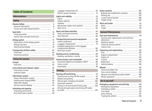 5
5 6
6 7
7 8
8 9
9 10
10 11
11 12
12 13
13 14
14 15
15 16
16 17
17 18
18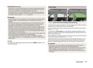 19
19 20
20 21
21 22
22 23
23 24
24 25
25 26
26 27
27 28
28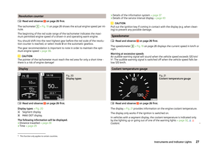 29
29 30
30 31
31 32
32 33
33 34
34 35
35 36
36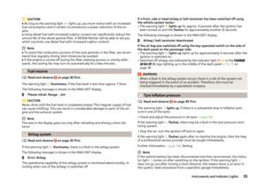 37
37 38
38 39
39 40
40 41
41 42
42 43
43 44
44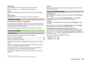 45
45 46
46 47
47 48
48 49
49 50
50 51
51 52
52 53
53 54
54 55
55 56
56 57
57 58
58 59
59 60
60 61
61 62
62 63
63 64
64 65
65 66
66 67
67 68
68 69
69 70
70 71
71 72
72 73
73 74
74 75
75 76
76 77
77 78
78 79
79 80
80 81
81 82
82 83
83 84
84 85
85 86
86 87
87 88
88 89
89 90
90 91
91 92
92 93
93 94
94 95
95 96
96 97
97 98
98 99
99 100
100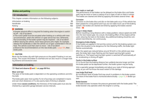 101
101 102
102 103
103 104
104 105
105 106
106 107
107 108
108 109
109 110
110 111
111 112
112 113
113 114
114 115
115 116
116 117
117 118
118 119
119 120
120 121
121 122
122 123
123 124
124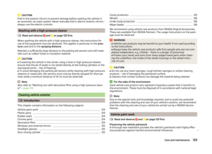 125
125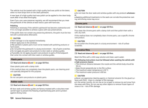 126
126 127
127 128
128 129
129 130
130 131
131 132
132 133
133 134
134 135
135 136
136 137
137 138
138 139
139 140
140 141
141 142
142 143
143 144
144 145
145 146
146 147
147 148
148 149
149 150
150 151
151 152
152 153
153 154
154 155
155 156
156 157
157 158
158 159
159 160
160 161
161 162
162 163
163 164
164 165
165 166
166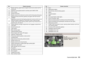 167
167 168
168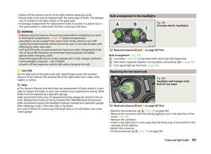 169
169 170
170 171
171 172
172 173
173 174
174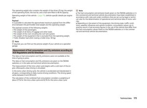 175
175 176
176 177
177 178
178 179
179 180
180 181
181 182
182 183
183 184
184 185
185 186
186 187
187 188
188 189
189 190
190 191
191 192
192