Page 185 of 315

WARNING
The jack provided is only intended to
be used for replacing tyres on the
car with which it is supplied, or on
same-model vehicles. Never use the jack for
other purposes, such as lifting other car
models. Never use it for repair operations
under the car. Incorrectly positioning the
jack may cause the car to fall. Do not use the
jack for loads higher than the one shown
on its label. Never install snow chains on the
space-saver wheel; if a front tyre (driving
wheel) is punctured and you need to use
snow chains, use a standard wheel from the
rear axle and install the space-saver wheel
on the rear axle. In this way, with two
normal drive wheels, it is possible to use
snow chains.
WARNING
Fit the wheel cap correctly to prevent
it from coming free in motion. Never
tamper with the inflating valve. Never
introduce tools of any kind between rim and
tyre. Check tyre and space-saver wheel
pressures regularly, referring to the values
shown in the "Technical specifications"
section.JACK
Important notes:
❒the jack weight is 1,76 kg;
❒the jack requires no adjustment;
❒the jack cannot be repaired and in the event of a
fault it must be replaced by another original
one;
❒no tool other than its cranking device may be
fitted on the jack.
181GETTING TO KNOW
YOUR CAR
SAFETY
STARTING AND
DRIVING
WARNING LIGHTS
AND MESSAGESIN AN EMERGENCYSERVICING AND
MAINTENANCE
TECHNICAL
SPECIFICATIONS
INDEX
Page 186 of 315
To change a wheel proceed as follows:
❒Stop the car in a position that is not dangerous
for oncoming traffic where you can change the
wheel safely. The ground must be flat and
sufficiently compact;
❒switch off the engine, pull up the handbrake
and engage the 1
stgear or the reverse gear.
Wear the reflective safety jacket (compulsory by
law in certain countries) before getting out of
the car;
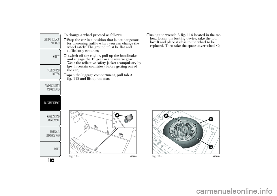
❒open the luggage compartment, pull tab A
fig. 115 and lift up the mat;❒using the wrench A fig. 116 located in the tool
box, loosen the locking device, take the tool
box B and place it close to the wheel to be
replaced. Then take the space-saver wheel C;
fig. 115
L0F0099
fig. 116
L0F0183
182
GETTING TO KNOW
YOUR CAR
SAFETY
STARTING AND
DRIVING
WARNING LIGHTS
AND MESSAGESIN AN EMERGENCYSERVICING AND
MAINTENANCE
TECHNICAL
SPECIFICATIONS
INDEX
Page 187 of 315

❒take the wrench A fig. 117 and loosen the fixing
bolts by about one turn. For versions with alloy
rims, shake the car to facilitate detachment of
the rim from the wheel hub.
❒position the jack under the car, near the wheel
to be changed;
❒operate the device A fig. 118 to extend the jack
until the top of the jack B fig. 119 fits correctly
into the side member C (next to the mark on
the side member);
❒alert other passengers that the car is about to be
raised; all persons should be kept away from the
car until it has been lowered;❒fit handle D fig. 118 into the housing in device
A, operate the jack and raise the car until the
wheel is a few centimetres from the ground;
❒remove the wheel cap after loosening the 3
fixing bolts and finally loosen the fourth bolt
and extract the wheel (only for versions with
wheel caps fixed by bolts);
❒make sure the contact surfaces between
space-saver wheel and hub are clean so that the
fastening bolts will not come loose;
❒fit the space-saver wheel by inserting the first
bolt for two threads into the hole closest to the
valve;
❒take the wrench A fig. 117 and fully tighten the
fixing bolts;
❒operate the jack handle D to lower the car. Then
extract the jack;
fig. 117
L0F0179
fig. 118
L0F0025
183GETTING TO KNOW
YOUR CAR
SAFETY
STARTING AND
DRIVING
WARNING LIGHTS
AND MESSAGESIN AN EMERGENCYSERVICING AND
MAINTENANCE
TECHNICAL
SPECIFICATIONS
INDEX
Page 188 of 315

❒use the wrench A provided to fully tighten the
bolts in a criss-cross fashion as per the order
illustrated in fig. 120;
❒when replacing an alloy wheel it is advisable to
place it upside down, with the aesthetic part
facing upwards.Restore the standard wheel as soon as possible,
because, once placed in the associated
compartment, the luggage compartment load
platform is rendered uneven as the standard wheel
is larger than the spare wheel.
REFITTING THE STANDARD WHEEL
Following the procedure described previously,
raise the car and remove the space-saver wheel.
Versions with steel rims
Proceed as follows:
❒make sure the contact surfaces between
standard wheel and hub are clean so that the
fastening bolts will not come loose;
❒fit the standard wheel inserting the 4 bolts into
the holes;
❒using the wrench provided, tighten the fastening
bolts; ❒press-fit the hub cap, aligning the special
splining (on the cap) with the inflation valve;
❒lower the car and remove the jack;
❒using the wrench provided, fully tighten the
bolts in the sequence shown previously.
fig. 119
L0F0024
fig. 120
L0F0182
184
GETTING TO KNOW
YOUR CAR
SAFETY
STARTING AND
DRIVING
WARNING LIGHTS
AND MESSAGESIN AN EMERGENCYSERVICING AND
MAINTENANCE
TECHNICAL
SPECIFICATIONS
INDEX
Page 189 of 315

Versions with alloy wheels
❒insert the wheel on the hub and using the
wrench provided tighten the bolts;
❒lower the car and remove the jack;
❒using the wrench provided, fully tighten the
bolts in the sequence shown ;
❒reinstall the pressure-fitted hub cap, making
sure that the reference hole on the wheel is
aligned with the reference hole on the cap.
IMPORTANT If it is not fitted properly, the hub
cap may detach itself when the car is running.
After tyre replacement
❒stow the space-saver wheel in the compartment
provided in the boot;
❒insert the jack and the other tools in the
container;
❒arrange the container and tools on the
space-saver wheel;
❒correctly reposition the boot stiff cover.
185GETTING TO KNOW
YOUR CAR
SAFETY
STARTING AND
DRIVING
WARNING LIGHTS
AND MESSAGESIN AN EMERGENCYSERVICING AND
MAINTENANCE
TECHNICAL
SPECIFICATIONS
INDEX
QUICK TYRE REPAIR KIT - Fix&GoIt is located in a special container in the luggage
compartment fig. 121. The container also contains a
screwdriver and the tow hook.
The Fix&Go kit fig. 122 consists of:
❒spray bottle A with the sealant, equipped with
filling pipe B, separated by the compressor C;
❒compressor C with pressure gauge, valve-fitting
to couple the bottle A, cable with supply socket
D and pipe N to restore pressure (the same is
inside the body as shown);
❒adhesive label under the spray bottle A, with the
message “max. 80 km/h” to be placed where
the driver can easily see it (for example on the
dashboard) after repairing the tyre;
fig. 121
L0F0307
Page 190 of 315

186
GETTING TO KNOW
YOUR CAR
SAFETY
STARTING AND
DRIVING
WARNING LIGHTS
AND MESSAGESIN AN EMERGENCYSERVICING AND
MAINTENANCE
TECHNICAL
SPECIFICATIONS
INDEX
❒instruction booklet fig. 123, explaining the
quick and correct use of the Fix&Go;
❒protective gloves.
fig. 122
L0F0300
fig. 123
L0F0301
WARNING
Give the booklet to the technicians
who will be handling the tyre that
was treated using the Fix&Go kit.
WARNING
In the event of a puncture caused by
foreign bodies, the kit may be used to
repair tyres showing damage on the track or
shoulder up to max 4 mm diameter. Holes
and damage on the tyre side walls cannot be
repaired. Do not attempt to use the Fix&Go
kit if the tyre was damaged as a result of
being used when underinflated.
WARNING
If the wheel rim has been damaged
(bent so as to cause pressure loss), the
wheel may not be repaired. Do not remove
the foreign body (screws or nails) from the
tyre.
IMPORTANT INFORMATION
The sealing fluid of the quick tyre repair kit is
effective at external temperatures of between
-20°C and +50°C.
Page 191 of 315

187GETTING TO KNOW
YOUR CAR
SAFETY
STARTING AND
DRIVING
WARNING LIGHTS
AND MESSAGESIN AN EMERGENCYSERVICING AND
MAINTENANCE
TECHNICAL
SPECIFICATIONS
INDEX
The sealing fluid has an expiry date.
WARNING
Never operate the compressor for
longer than 20 consecutive minutes.
Risk of overheating. The Fix&Go kit is not
suitable for definitive repairs, so the
repaired tyres may only be used temporarily.
WARNING
The bottle contains ethylene glycol. It
contains latex that might cause
allergic reactions. It is harmful if swallowed.
It is irritant for the eyes. May cause a
reaction if inhaled or on contact. Avoid
contact with eyes, skin and clothes. In the
event of contact, wash immediately with
plenty of water. If ingested, do not induce
vomiting. Rinse out your mouth, drink large
quantities of water and seek immediate
medical attention. Keep out of the reach of
children. The product must not be used
by asthmatics. Do not inhale the vapours
during insertion and suction. Call a doctor
immediately if allergic reactions are noted.
Store the spray bottle away from heat
sources. The sealing fluid has an expiry
date.
Replace the bottle if the sealing fluid
has expired. Dispose of the bottle
and the sealant liquid properly. Have
the sealing fluid and the bottle disposed of in
compliance with national and local
regulations.
INFLATION PROCEDURE
WARNING
Wear the protective gloves provided
with the Fix&Go kit.
To carry out the inflation procedure proceed as
follows:
❒engage the handbrake;
❒place the Fix&Go kit close to the tyre to be
repaired;
❒locate the filler pipe fig. 124 already
connected to the spray bottle A;
❒open the side lid E fig. 125 then connect the
spray bottle A to the fitting, following the
direction of the arrow;
❒undo the cap of the tyre valve F and connect the
filling pipe B tightening the relevant ring nut on
the tyre valve;
❒Make sure that the switch G fig. 126 is in position
0(off), then start the engine;
Page 192 of 315
188
GETTING TO KNOW
YOUR CAR
SAFETY
STARTING AND
DRIVING
WARNING LIGHTS
AND MESSAGESIN AN EMERGENCYSERVICING AND
MAINTENANCE
TECHNICAL
SPECIFICATIONS
INDEX
❒place the electric plug H fig. 127 in the cigar
lighter socket of the car (12 V);
❒start the compressor, placing the switch G to
position1(on);
fig. 124
L0F0302
fig. 126
L0F0304
❒inflate the tyre to the pressure specified (see
"Cold tyre inflation pressure" paragraph in
the "Technical specifications" section);
fig. 125
L0F0303