Page 57 of 95

13. If necessary, add prediluted engine coolant to the coolant reservoir
until the coolant level is within the COLD FILL RANGE as listed on the
reservoir. After any coolant has been added, check the coolant
concentration. SeeEngine and secondary cooling system coolant
earlier in the chapter for more information.
Whenever coolant has been added, the coolant level in the reservoir
should be checked the next few times you drive the vehicle. If needed,
add prediluted engine coolant to bring the coolant to the proper level.
Recycled engine coolant
Ford Motor Company does not recommend the use of recycled engine
coolant since a Ford-approved recycling process is not yet available.
Always dispose of used automotive fluids in a responsible manner. Follow
your community’s regulations and standards for recycling and disposing
of automotive fluids.
Coolant refill capacity
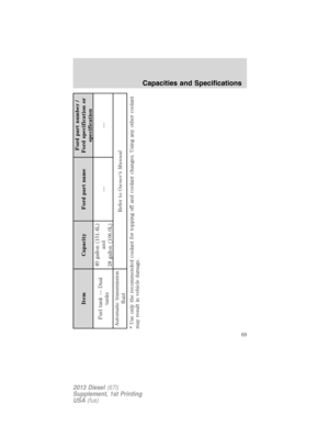
To find out how much fluid your vehicle’s cooling system can hold, refer
to theCapacities and Specificationschapter.
Severe climates
If you drive in extremely cold climates:
•It may be necessary to have a Ford authorized dealer increase the
coolant concentration above 50%.
•A coolant concentration of 60% will provide improved freeze point
protection. Engine coolant concentrations above 60% will decrease the
overheat protection characteristics of the engine coolant and may
cause engine damage.
If you drive in extremely hot climates:
•It may be necessary to have a Ford authorized dealer decrease the
coolant concentration to 40%.
•A coolant concentration of 40% will provide improved overheat
protection. Engine coolant concentrations below 40% will decrease the
corrosion/freeze protection characteristics of the engine coolant and
may cause engine damage.
Vehicles driven year-round in non-extreme climates should use
prediluted engine coolant for optimum cooling system and engine
protection.
Maintenance
56
2013 Diesel(67l)
Supplement, 1st Printing
USA(fus)
Page 58 of 95
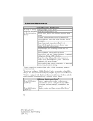
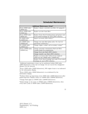
, as listed in the
scheduled maintenance informationchapter, the coolant corrosion
inhib")
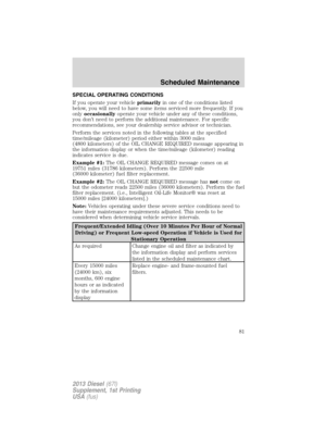
Checking coolant corrosion inhibitor additive strength
At specific mileage intervals of 15,000 miles (24,000 km), as listed in the
scheduled maintenance informationchapter, the coolant corrosion
inhibitor additive should be checked. The optional information display, if
equipped, will also display the messageCHECK COOLANT ADDITIVE
at this time. The purpose of checking is to verify the correct engine
coolant concentration (freeze point protection) and corrosion inhibitor
additive level (strength) of the coolant for maximum engine performance
and protection. Three products are available for ensuring the life and
health of the coolant: one tool, a test kit and a coolant inhibitor additive:
•Rotunda tool 300–ROB75240 available from your dealer –
recommended refractometer to test coolant concentration.
•
Rotunda 328-R071–ELC (Antifreeze Coolant ELC Contamination Kit) –
Evaluates the corrosion inhibitor additive strength. Note the first step is
to verify the vehicle’s coolant concentration is in the correct range of 40
– 60%. Coolant concentrations outside this range will not provide valid
test results. If the report results in a pass (i.e., the cooling system does
not show excessive contamination/the corrosion inhibitor additive
strength is sufficient), no action is required. If the report results as
insufficient (does not pass), the corrosion inhibitor additive strength of
the coolant is too low. If the ENGINE COOLING SYSTEM corrosion
inhibitor additive strength is low, add 48 fluid oz. of Motorcraft®
Specialty Orange Engine Coolant Revitalizer. If the SECONDARY
COOLING SYSTEM corrosion inhibitor additive strength is low, add 16
fluid oz. of Motorcraft® Specialty Orange Engine Coolant Revitalizer.
•Motorcraft® Specialty Orange Engine Coolant Revitalizer – Additive to
boost the corrosion inhibitor level based upon the test results of the
Antifreeze Coolant ELC Contamination Kit. The Revitalizer may be
added two times over the life of the coolant. If additional dosages are
required, the cooling system must be flushed and refilled per the
instructions in the Workshop Manual.
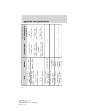
Refer to theCapacities and Specificationschapter for the proper
coolant and additive specifications.
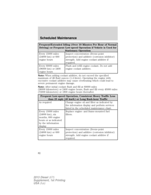
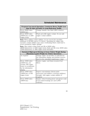
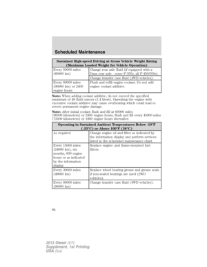
Coolant change
At specific mileage intervals, as listed in thescheduled maintenance
information,the coolant should be changed. The optional information
display, if equipped, will also display the messageCOOLANT CHANGE
REQUIREDat this time.
Refer to theCapacities and Specificationschapter for the proper coolant.
Maintenance
57
2013 Diesel(67l)
Supplement, 1st Printing
USA(fus)
Page 59 of 95

Your vehicle is equipped with an engine driven cooling fan drive (also
called a fan clutch). This fan drive changes the fan speed to match the
vehicle’s changi")
Engine-driven cooling fan (fan clutch)
Your vehicle is equipped with an engine driven cooling fan drive (also
called a fan clutch). This fan drive changes the fan speed to match the
vehicle’s changing cooling air flow requirements. Fan speed, fan noise
level and fuel consumption all will increase based on the driving
conditions that include trailer towing, hill climbing, heavy loads, high
speed and high ambient temperature, individually or in combination.
The fan drive is designed to provide the minimum fan speed (and
resulting minimum fan noise and fuel consumption) required to meet the
ever changing vehicle cooling air flow requirements. You will hear the
amount of fan noise increasing and decreasing as the engine power
requirements and vehicle driving conditions change as you drive. This is
to be expected as being normal to the operation of your vehicle. High
levels of fan noise might also be heard when your engine is first started,
and should normally decrease after driving for a short time.
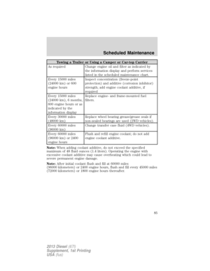
AIR FILTER RESTRICTION GAUGE AND AIR FILTER REPLACEMENT
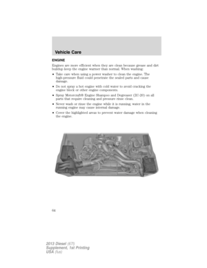
WARNING:To reduce the risk of vehicle damage and/or
personal burn injuries do not start your engine with the air filter
removed and do not remove it while the engine is running.
Note:Vehicle operation in heavy snowfall or extreme rain conditions
may feed excessive amounts of snow/water into the air intake system.
This could plug/soak the air filter with snow and may cause the engine to
lose power and possibly shut down.
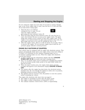
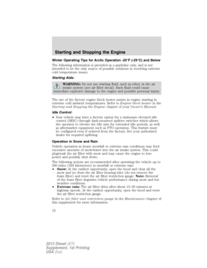
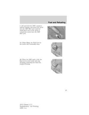
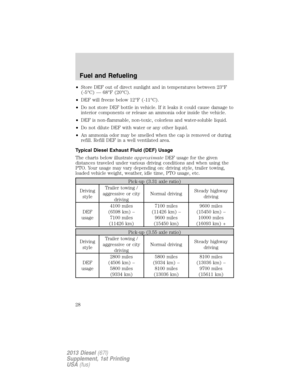
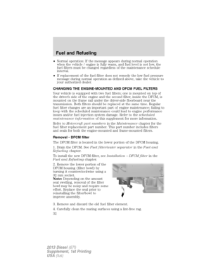
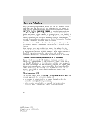
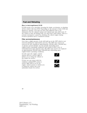
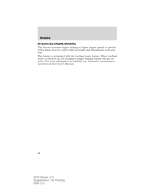
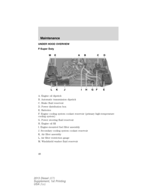
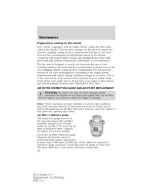
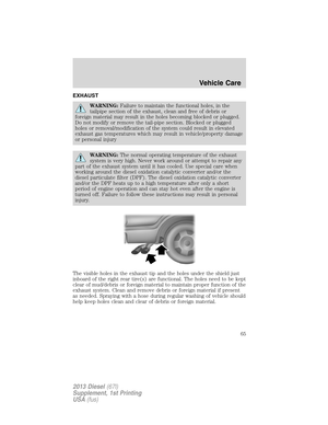
Air filter restriction gauge:
The restriction gauge, located on
the upper housing of the air filter
assembly, measures the vacuum
inside the air filter. The more the air
filter is restricted (dirty, clogged),
the higher the vacuum reading
Check the air filter restriction gauge
whenever the hood is raised to
perform general engine maintenance
at least every 7,500 miles (12,000 km). If the vehicle is operated in
extremely dusty conditions, check and reset the gauge at least every
500 miles (800 km), or two weeks, whichever comes first.
Maintenance
58
2013 Diesel(67l)
Supplement, 1st Printing
USA(fus)
Page 60 of 95

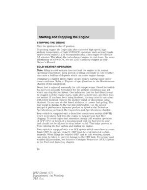
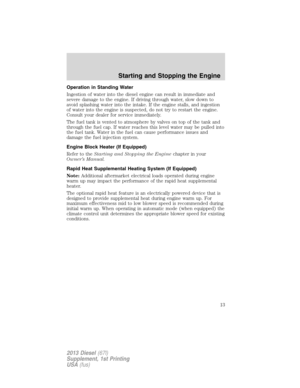
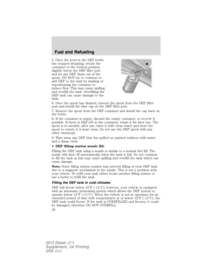
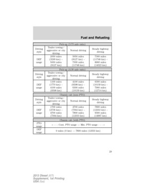
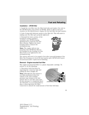
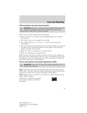
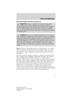
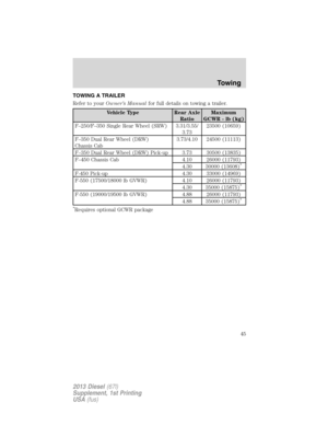
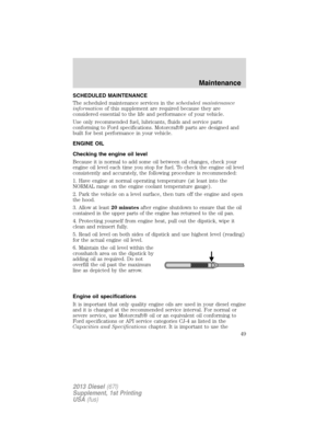
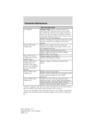
Change the air filter when the gauge reads near the “change filter” line
and the chamber is filled with yellow. Engine performance and fuel
economy are adversely affected when the maximum restriction is
reached.
Blowing-out the air filter element with compressed air is not
recommended as the compressed air may damage the filter paper.
Note:It is not possible to determine the level of filter clogging by visual
appearance alone. A filter which appears to be dirty may actually have
several thousand miles (kilometers) of life remaining.
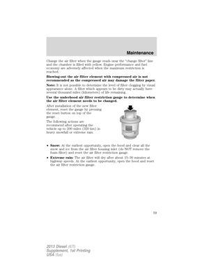
Use the underhood air filter restriction gauge to determine when
the air filter element needs to be changed.
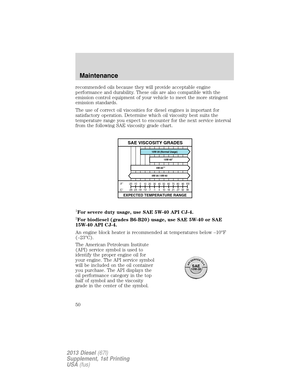
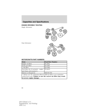
After installation of the new filter
element, reset the gauge by pressing
the reset button on top of the
gauge.
The following actions are
recommend after operating the
vehicle up to 200 miles (320 km) in
heavy snowfall or extreme rain:
•Snow:At the earliest opportunity, open the hood and clear all the
snow and ice from the air filter housing inlet (do NOT remove the
foam filter) and reset the air filter restriction gauge.
•Extreme rain:The air filter will dry after about 15–30 minutes at
highway speeds. At the earliest opportunity, open the hood and reset
the air filter restriction gauge.
Maintenance
59
2013 Diesel(67l)
Supplement, 1st Printing
USA(fus)
Page 61 of 95
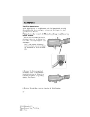
Air filter replacement:
When replacing the air filter element, use the Motorcraft® air filter
element listed inMotorcraft part numbersin theCapacities and
Specificationschapter.
Failure to use the correct air filter element may result in severe
engine damage.
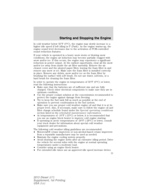
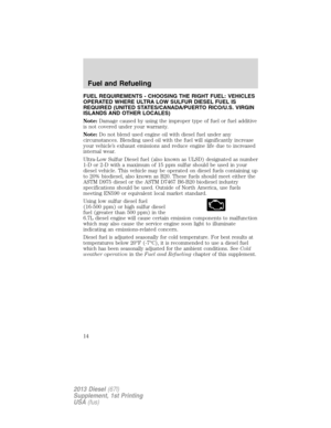
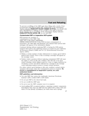
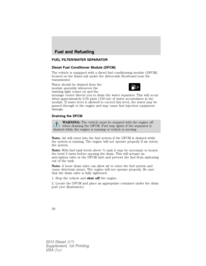
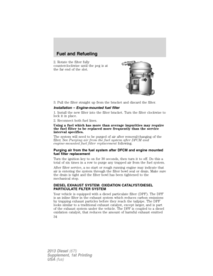
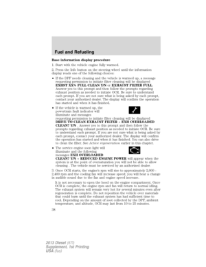
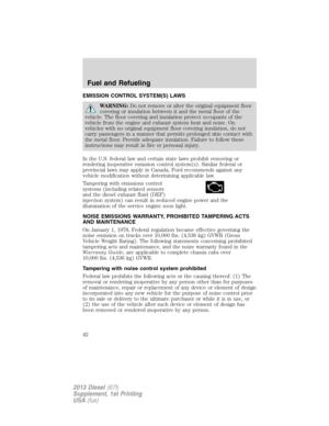
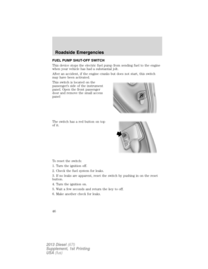
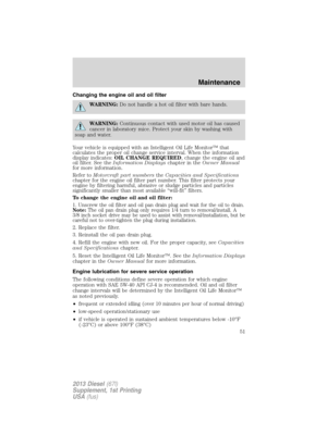
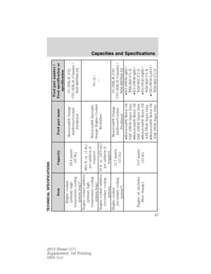
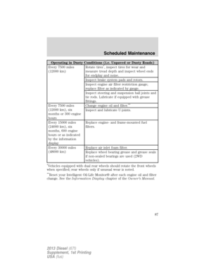
1. Locate the mass air flow sensor
electrical connector on the air inlet
tube. This connector will need to be
unplugged.
Unlock the locking clip on the
connector, then squeeze and pull
the connector off of the air inlet
tube.
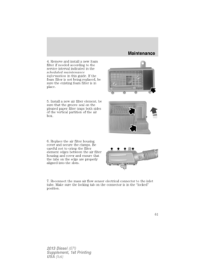
2. Release the four clamps that
secure the cover to the air filter
housing. Push the air filter cover
forward (away from you) and up
slightly to release it.
3. Remove the air filter element from the air filter housing.
Maintenance
60
2013 Diesel(67l)
Supplement, 1st Printing
USA(fus)
Page 62 of 95
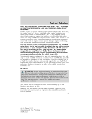
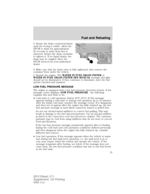
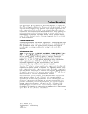
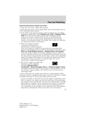
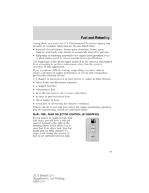
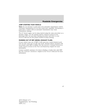
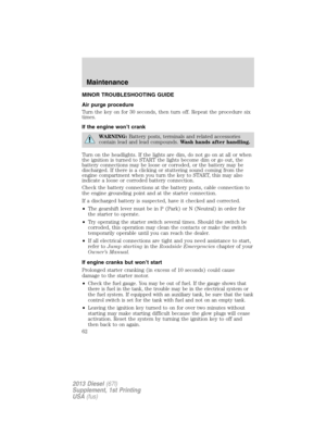
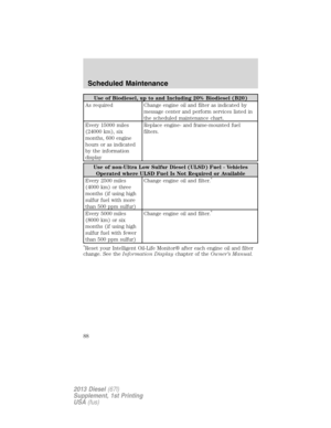
4. Remove and install a new foam
filter if needed according to the
service interval indicated in the
scheduled maintenance
informationin this guide. If the
foam filter is not being replaced, be
sure the existing foam filter is in
place.
5. Install a new air filter element. be
sure that the groove seal on the
pleated paper filter traps both sides
of the vertical partition of the air
box.
6. Replace the air filter housing
cover and secure the clamps. Be
careful not to crimp the filter
element edges between the air filter
housing and cover and ensure that
the tabs on the edge are properly
aligned into the slots.
7. Reconnect the mass air flow sensor electrical connector to the inlet
tube. Make sure the locking tab on the connector is in the “locked”
position.
Maintenance
61
2013 Diesel(67l)
Supplement, 1st Printing
USA(fus)
Page 63 of 95

MINOR TROUBLESHOOTING GUIDE
Air purge procedure
Turn the key on for 30 seconds, then turn off. Repeat the procedure six
times.
If the engine won’t crank
WARNING:Battery posts, terminals and related accessories
contain lead and lead compounds.Wash hands after handling.
Turn on the headlights. If the lights are dim, do not go on at all or when
the ignition is turned to START the lights become dim or go out, the
battery connections may be loose or corroded, or the battery may be
discharged. If there is a clicking or stuttering sound coming from the
engine compartment when you turn the key to START, this may also
indicate a loose or corroded battery connection.
Check the battery connections at the battery posts, cable connection to
the engine grounding point and at the starter connection.
If a discharged battery is suspected, have it checked and corrected.
•The gearshift lever must be in P (Park) or N (Neutral) in order for
the starter to operate.
•Try operating the starter switch several times. Should the switch be
corroded, this operation may clean the contacts or make the switch
temporarily operable until you can reach the dealer.
•If all electrical connections are tight and you need assistance to start,
refer toJump startingin theRoadside Emergencieschapter of your
Owner’s Manual.
If engine cranks but won’t start
Prolonged starter cranking (in excess of 10 seconds) could cause
damage to the starter motor.
•
Check the fuel gauge. You may be out of fuel. If the gauge shows that
there is fuel in the tank, the trouble may be in the electrical system or
the fuel system. If equipped with an auxiliary tank, be sure that the tank
control switch is set for the tank with fuel and not on an empty tank.
•Leaving the ignition key turned to on for over two minutes without
starting may make starting difficult because the glow plugs will cease
activation. Reset the system by turning the ignition key to off and
then back to on again.
Maintenance
62
2013 Diesel(67l)
Supplement, 1st Printing
USA(fus)
Page 64 of 95

If the engine runs hot
The following could cause the engine to overheat:
•Lack of coolant.
•Dirty cooling system.
•Plugged radiator fins, A/C condenser and/or oil cooler.
•Malfunctioning fan drive.
•Driving with frozen coolant.
•Sticking thermostat.
•Overloading or pulling heavy trailers during hot weather.
•Grill or radiator air blockage.
•Slipping or missing drive belt.
•Plugged or very dirty air filter.
If fuses burn out
WARNING:Replacement fuses and circuit breakers must always
be the same rating as the original equipment shown. Never
replace a fuse or circuit breaker with one of a higher rating. Higher
rated fuses or circuit breakers could allow circuit overloading in the
event of a circuit malfunction, resulting in severe vehicle damage or
personal injury due to fire.
Burned-out or blown fuses usually indicate an electrical short-circuit,
although a fuse may occasionally burn out from vibration. Insert a second
fuse. If this fuse immediately burns out and you cannot locate the cause,
return your vehicle to your dealer for a circuit check.
Refer to theOwner’s Manualfor replacement of fuses.
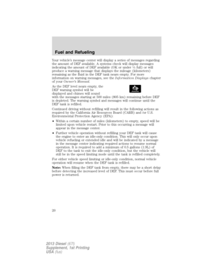
Selective catalytic reduction (SCR) system speed limit and
Idle-only modes
If the vehicle’s speed is limited or in an idle-only mode, the SCR system
may be limiting the vehicle’s functions due to low or contaminated diesel
exhaust fluid (DEF). Check the DEF. SeeSelective catalytic reduction
(SCR) systemin theFuel and Refuelingchapter for more information.
Maintenance
63
2013 Diesel(67l)
Supplement, 1st Printing
USA(fus)