Page 623 of 715

09-154891-01
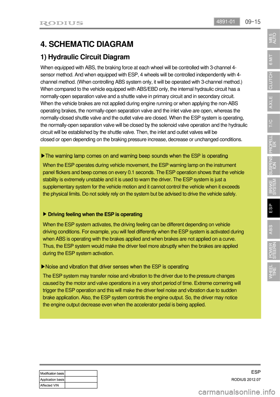
4. SCHEMATIC DIAGRAM
When equipped with ABS, the braking force at each wheel will be controlled with 3-channel 4-
sensor method. And when equipped with ESP, 4 wheels will be controlled independently with 4-
channel method. (When controlling ABS system only, it will be operated with 3-channel method.)
When compared to the vehicle equipped with ABS/EBD only, the internal hydraulic circuit has a
normally-open separation valve and a shuttle valve in primary circuit and in secondary circuit.
When the vehicle brakes are not applied during engine running or when applying the non-ABS
operating brakes, the normally-open separation valve and the inlet valve are open, whereas the
normally-closed shuttle valve and the outlet valve are closed. When the ESP system is operating,
the normally-open separation valve will be closed by the solenoid valve operation and the hydraulic
circuit will be established by the shuttle valve. Then, the inlet and outlet valves will be
closed or open depending on the braking pressure increase, decrease or unchanged conditions.
▶The warning lamp comes on and warning beep sounds when the ESP is operating
Driving feeling when the ESP is operating ▶
▶Noise and vibration that driver senses when the ESP is operating
1) Hydraulic Circuit Diagram
When the ESP operates during vehicle movement, the ESP warning lamp on the instrument
panel flickers and beep comes on every 0.1 seconds. The ESP operation shows that the vehicle
stability is extremely unstable and it is used to warn the driver. The ESP system is just a
supplementary system for the vehicle motion and it cannot control the vehicle when it exceeds
the physical limits. Do not solely rely on the system but be advised to drive the vehicle safely.
When the ESP system activates, the driving feeling can be different depending on vehicle
driving conditions. For example, you will feel differently when the ESP system is activated during
when ABS is operating with the brakes applied and when brakes are not applied on a curve.
Thus, the ESP system would make the driver feel more abruptly when the brakes are applied
during the ESP system activation.
The ESP system may transfer noise and vibration to the driver due to the pressure changes
caused by the motor and valve operations in a very short period of time. Extreme cornering will
trigger the ESP operation and this will make the driver feel noise and vibration due to sudden
brake application. Also, the ESP system controls the engine output. So, the driver may notice
the engine output decrease even when the accelerator pedal is being applied.
Page 624 of 715
09-16
(1) Hydraulic Circuit Diagram
When compared to the vehicle equipped with ABS/EBD only, the internal hydraulic circuit has a
normally-open separation valve and a shuttle valve in primary circuit and in secondary circuit.
When the vehicle brakes are not applied during engine running or when applying the non-ABS
operating brakes, the normally-open separation valve and the inlet valve are open, whereas the
normally-closed shuttle valve and the outlet valve are closed.
When the ESP system is operating, the normally-open separation valve will be closed by the
solenoid valve operation and the hydraulic circuit will be established by the shuttle valve. Then,
the inlet and outlet valves will be closed or open depending on the braking pressure RISE, HOLD
or DUMP conditions.
Page 645 of 715

11-74610-00
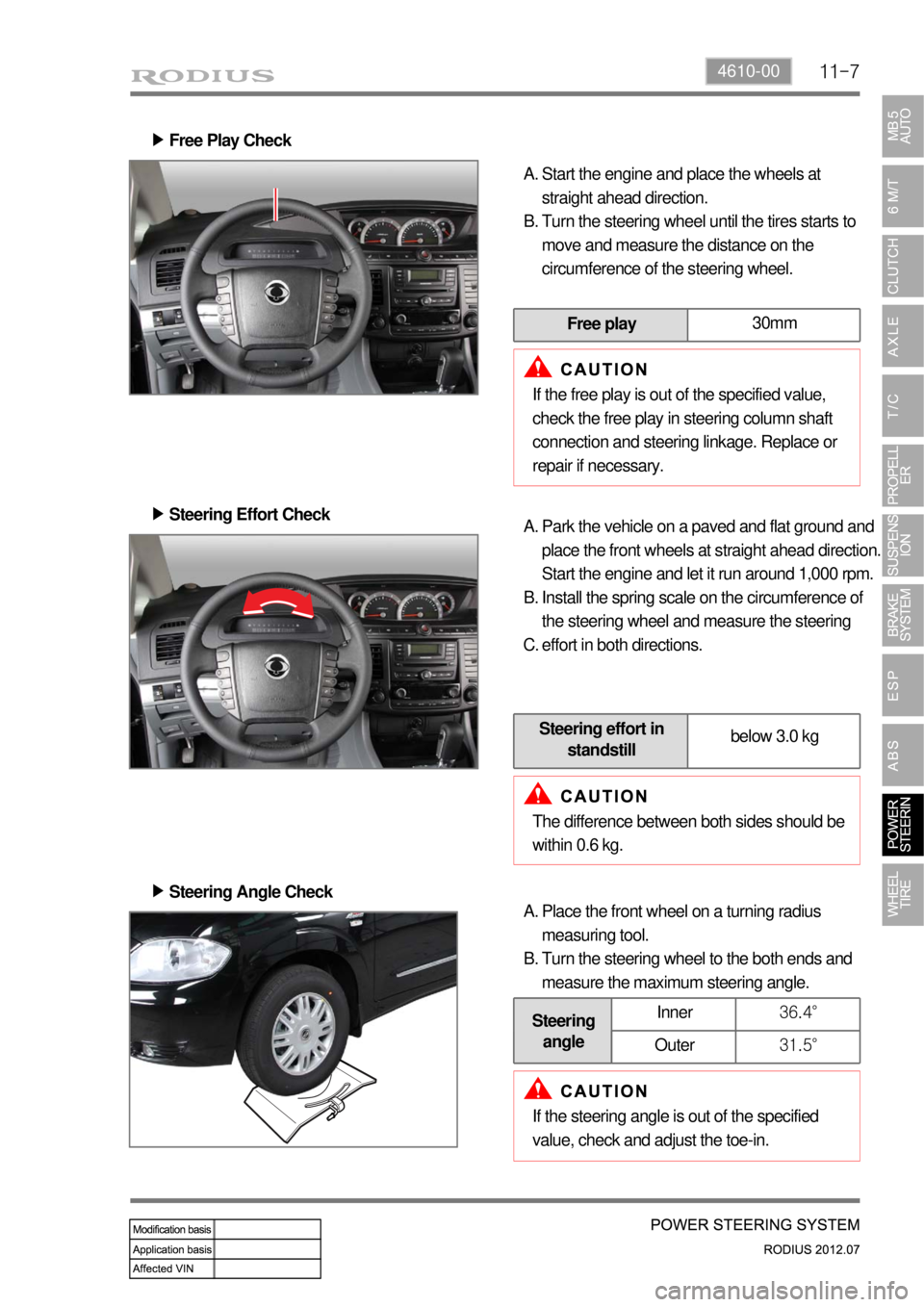
Free Play Check ▶
Start the engine and place the wheels at
straight ahead direction.
Turn the steering wheel until the tires starts to
move and measure the distance on the
circumference of the steering wheel. A.
B.
Free play30mm
If the free play is out of the specified value,
check the free play in steering column shaft
connection and steering linkage. Replace or
repair if necessary.
Steering Effort Check ▶
Park the vehicle on a paved and flat ground and
place the front wheels at straight ahead direction.
Start the engine and let it run around 1,000 rpm.
Install the spring scale on the circumference of
the steering wheel and measure the steering
effort in both directions. A.
B.
C.
Steering effort in
standstillbelow 3.0 kg
The difference between both sides should be
within 0.6 kg.
Steering Angle Check ▶
Place the front wheel on a turning radius
measuring tool.
Turn the steering wheel to the both ends and
measure the maximum steering angle. A.
B.
Steering
angleInner36.4°
Outer31.5°
If the steering angle is out of the specified
value, check and adjust the toe-in.
Page 646 of 715

11-8
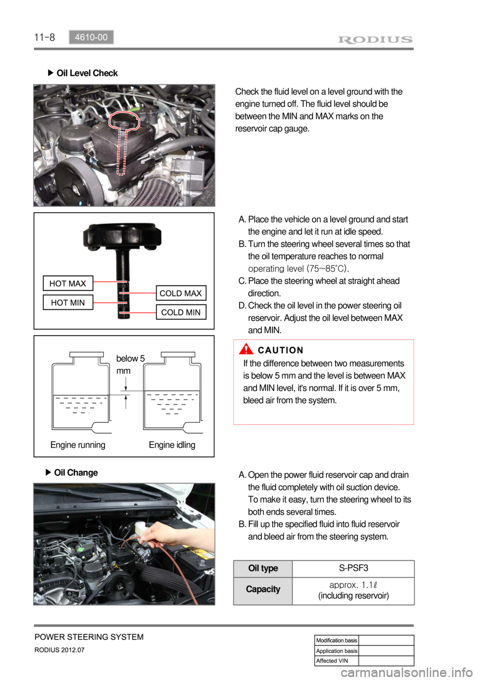
Oil Level Check ▶
Check the fluid level on a level ground with the
engine turned off. The fluid level should be
between the MIN and MAX marks on the
reservoir cap gauge.
Place the vehicle on a level ground and start
the engine and let it run at idle speed.
Turn the steering wheel several times so that
the oil temperature reaches to normal
operating level (75~85˚C).
Place the steering wheel at straight ahead
direction.
Check the oil level in the power steering oil
reservoir. Adjust the oil level between MAX
and MIN. A.
B.
C.
D.
Oil Change ▶
If the difference between two measurements
is below 5 mm and the level is between MAX
and MIN level, it's normal. If it is over 5 mm,
bleed air from the system.
Open the power fluid reservoir cap and drain
the fluid completely with oil suction device.
To make it easy, turn the steering wheel to its
both ends several times.
Fill up the specified fluid into fluid reservoir
and bleed air from the steering system. A.
B.
Oil typeS-PSF3
Capacityapprox. 1.1ℓ
(including reservoir)
below 5
mm
Engine running Engine idling
Page 647 of 715
11-94610-00
Air Bleeding ▶
The air bleeding should be done after servicing the
power steering system and when the difference
between two measurements (cooled and normal
temperature) is prominent.
Normal AbnormalLift up the vehicle very carefully.
Turn the steering wheel to its both ends
several times and add the oil up to MAX line
in the steering oil reservoir.
Periodically crank the starting motor and turn
the steering wheel to its both ends without
any interruption.
Check the oil level again. If the oil level is
fluctuated, repeat the procedures from step 3
to step 5.
Start the engine.
Turn the steering wheel to its both ends until
any bubble can be found in the steering oil
reservoir.
Perform the test drive and check the steering
wheel for normal operation and noise.
If the oil level abruptly goes up, bleed the air
from the system again. A.
B.
C.
D.
E.
F.
G.
H.
If the air bleeding is not properly performed,
the life span of the power steering pump may
be shortened. -
Page 648 of 715
11-10
Oil Pump Pressure Check ▶
Check the oil pump pressure to locate any defect
in oil pump.
Before checking the pressure, check the oil
level and belt tension. Prepare the empty
container to collect the spilled oil during the
service.
Unscrew the pressure line fitting in power
steering pump.
Install the pressure gauge between the
power steering pump and the power steering
oil pressure line.
Place the shift lever to neutral position. Apply
the parking brake.
Open the valve in pressure gauge. Start the
engine and let it run at idle speed.
Turn the steering wheel several times so that
the oil temperature reaches to normal
operating level. A.
B.
C.
D.
E.
Fully close the valve in pressure gauge and
measure the oil pressure. F.
To prevent internal damage, do not close the
gauge valve over 10 seconds.
Keep the oil temperature at proper range. -
-
Relief pressure90 ± 3 bar
Page 649 of 715
11-114610-00
Measure the oil pressure with the gauge valve
fully open. G.
Pressure at no load3 ~ 5bar
If the pump pressure is in specified range, the
pump is normal. If not, replace the power
steering pump H.
Turn the steering wheel righ or left until it
stops with the engine idling ans valve fully
open. I.
Oil pressure78 ~ 83bar
Page 657 of 715
01-2
Front air conditioner module assembly - inside instrument panel
Compressor - engine rightAQS/Air source selection
switch
Sun load sensor - instrument
panel upper left
1. SYSTEM LAYOUT AND COMPONENTS
Type Air cindotioner controller
FATC
Manual air
conditioner
It change sun load coming through
front windshield into current to input to
FATC controller. *
Air mix door
actuator
PTC (If equipped)
Duct temperature
sensor
Mode door
actuator
Air conditioner wiring
Thermo AMP
Air source door
actuator
Air conditioner
filter
Bloewr motor
Blower high speed relayPower transistor