Page 362 of 600

1914-01
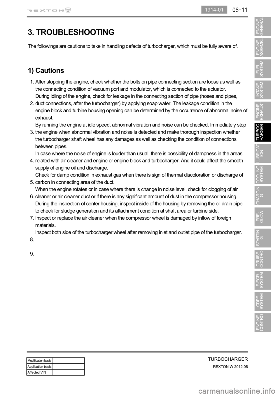
3. TROUBLESHOOTING
The followings are cautions to take in handling defects of turbocharger, which must be fully aware of.
1) Cautions
After stopping the engine, check whether the bolts on pipe connecting section are loose as well as
the connecting condition of vacuum port and modulator, which is connected to the actuator.
During idling of the engine, check for leakage in the connecting section of pipe (hoses and pipes,
duct connections, after the turbocharger) by applying soap water. The leakage condition in the
engine block and turbine housing opening can be determined by the occurrence of abnormal noise o
f
exhaust.
By running the engine at idle speed, abnormal vibration and noise can be checked. Immediately stop
the engine when abnormal vibration and noise is detected and make thorough inspection whether
the turbocharger shaft wheel has any damages as well as checking the condition of connections
between pipes.
In case where the noise of engine is louder than usual, there is possibility of dampness in the areas
related with air cleaner and engine or engine block and turbocharger. And it could affect the smooth
supply of engine oil and discharge.
Check for damp condition in exhaust gas when there is sign of thermal discoloration or discharge of
carbon in connecting area of the duct.
When the engine rotates or in case where there is change in noise level, check for clogging of air
cleaner or air cleaner duct or if there is any significant amount of dust in the compressor housing.
During the inspection of center housing, inspect inside of the housing by removing the oil drain pipe
to check for sludge generation and its attachment condition at shaft area or turbine side.
Inspect or replace the air cleaner when the compressor wheel is damaged by inflow of foreign
materials.
Inspect both side of the turbocharger wheel after removing inlet and outlet pipe of the turbocharger. 1.
2.
3.
4.
5.
6.
7.
8.
9.
Page 375 of 600

2. MAINTENANCE
1) Level Check
Park the vehicle on a level ground and apply the parking brake. Stop the engine and wait more than 5
minutes.
Pull out the dipstick and wipe it with a clean cloth. Reinsert it all the way.
Pull out it again and check the oil level.
The oil level should be between the maximum (Max) mark and minimum (Min) mark on the oil dipstick.
Oil should be replenished before the level goes below the minimum mark. -
-
-
Operating vehicle with insufficient amount of oil can damage the engine. Make sure the engine oil
level is correct and add oil if necessary.
2) Replenishment
If the level gets to the lower point, open the filler cap on top of the cylinder block and add the genuine oil
without exceeding the level of the upper mark.
Recheck the oil level after 5 minutes.
Regularly check the engine oil level and add Ssangyong genuine engine oil if necessary.
Clean the dipstick with clean cloth so that any foreign materials cannot get into the engine.
The oil should not go above the upper mark on the dipstick.
The engine oil may be consumed more if the engine is new. -
-
-
-
Engine oil dipstickEngine oil filler
Page 379 of 600

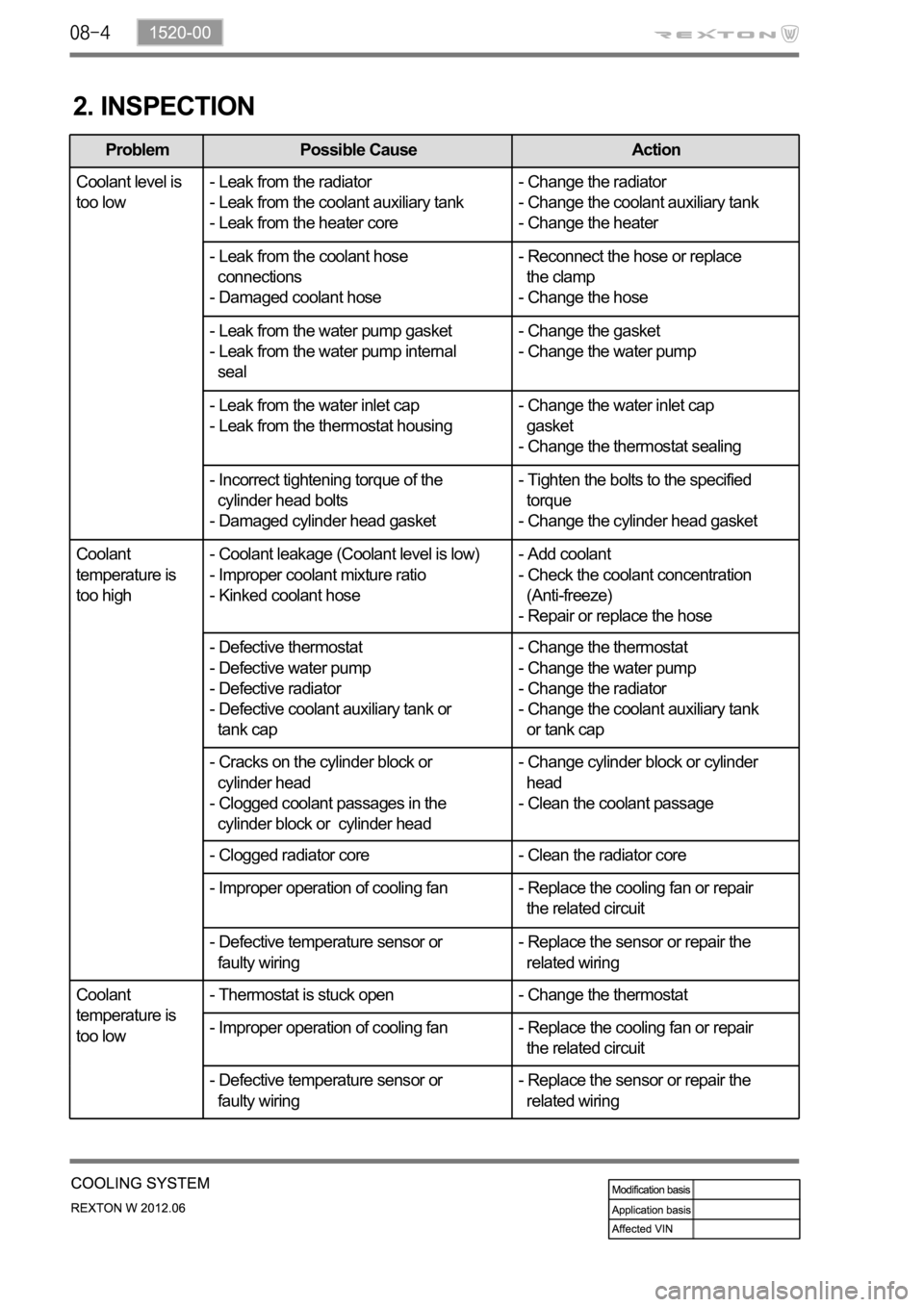
2. INSPECTION
Problem Possible Cause Action
Coolant level is
too low- Leak from the radiator
- Leak from the coolant auxiliary tank
- Leak from the heater core- Change the radiator
- Change the coolant auxiliary tank
- Change the heater
- Leak from the coolant hose
connections
- Damaged coolant hose- Reconnect the hose or replace
the clamp
- Change the hose
- Leak from the water pump gasket
- Leak from the water pump internal
seal- Change the gasket
- Change the water pump
- Leak from the water inlet cap
- Leak from the thermostat housing- Change the water inlet cap
gasket
- Change the thermostat sealing
- Incorrect tightening torque of the
cylinder head bolts
- Damaged cylinder head gasket- Tighten the bolts to the specified
torque
- Change the cylinder head gasket
Coolant
temperature is
too high- Coolant leakage (Coolant level is low)
- Improper coolant mixture ratio
- Kinked coolant hose- Add coolant
- Check the coolant concentration
(Anti-freeze)
- Repair or replace the hose
- Defective thermostat
- Defective water pump
- Defective radiator
- Defective coolant auxiliary tank or
tank cap- Change the thermostat
- Change the water pump
- Change the radiator
- Change the coolant auxiliary tank
or tank cap
- Cracks on the cylinder block or
cylinder head
- Clogged coolant passages in the
cylinder block or cylinder head- Change cylinder block or cylinder
head
- Clean the coolant passage
- Clogged radiator core - Clean the radiator core
- Improper operation of cooling fan - Replace the cooling fan or repair
the related circuit
- Defective temperature sensor or
faulty wiring- Replace the sensor or repair the
related wiring
Coolant
temperature is
too low- Thermostat is stuck open - Change the thermostat
- Improper operation of cooling fan - Replace the cooling fan or repair
the related circuit
- Defective temperature sensor or
faulty wiring- Replace the sensor or repair the
related wiring
Page 390 of 600

(3) Starting with jumper cable
If the battery is weak or terminated, the battery from another vehicle can be used with jumper cables to
start the engine.
Connecting order
The positive (+) terminal of the discharged battery
The positive (+) terminal of the booster battery
The negative (-) terminal of the booster battery
Connect one end of the other jumper cable to the body of the discharged vehicle, such as the engine
block or a front towing hook. 1.
2.
3.
4.
Starting
Prepare a set of jumper cables.
Place another vehicle that has the same 12 V of power near to the discharged vehicle.
Switch off all electrical accessories for the discharged vehicle.
Apply the parking brake and shift the transaxle to the P position (automatic transaxle) or neutral (N)
position (manual transaxle).
Connect the jumper cables.
Try to start the discharged vehicle while accelerating the engine rpm in the booster vehicle.
Attempt to start the engine with the discharged battery.
After starting the engine, carefully disconnect the jumper cables in the reverse sequence of
connection. 1.
2.
3.
4.
5.
6.
7.
8.
Page 405 of 600
1461-01
1. SPECIFICATION
Description Specification
Capacity 12 V, 2.3 kW
Engagement Meshed type
Rotating direction Clockwise
Pinion gear manufacturing Cooled forging
Solenoid operating voltage Max. 8 V
Weight 2.5 kg
Bracket manufacturing Aluminum die casting
Page 444 of 600
2. SYSTEM OPERATION
1) Input/Output of ECU
(1) ECU Block diagram
Page 454 of 600

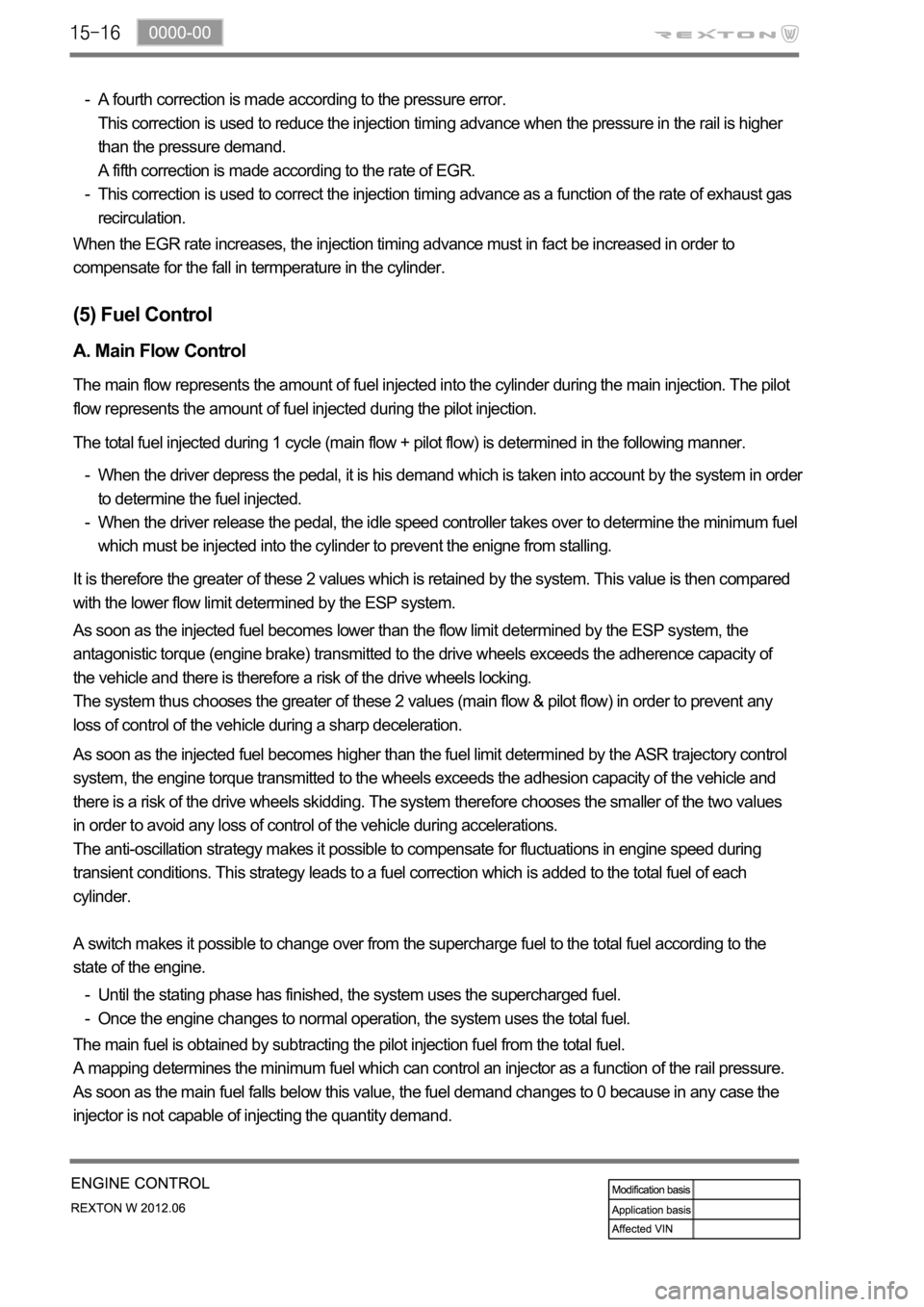
A fourth correction is made according to the pressure error.
This correction is used to reduce the injection timing advance when the pressure in the rail is higher
than the pressure demand.
A fifth correction is made according to the rate of EGR.
This correction is used to correct the injection timing advance as a function of the rate of exhaust gas
recirculation. -
-
<003a004b0048005100030057004b004800030028002a0035000300550044005700480003004c00510046005500480044005600480056000f00030057004b00480003004c0051004d004800460057004c0052005100030057004c0050004c0051004a000300
44004700590044005100460048000300500058005600570003[in fact be increased in order to
compensate for the fall in termperature in the cylinder.
A. Main Flow Control
The main flow represents the amount of fuel injected into the cylinder during the main injection. The pilot
flow represents the amount of fuel injected during the pilot injection.
The total fuel injected during 1 cycle (main flow + pilot flow) is determined in the following manner.
When the driver depress the pedal, it is his demand which is taken into account by the system in order
to determine the fuel injected.
When the driver release the pedal, the idle speed controller takes over to determine the minimum fuel
which must be injected into the cylinder to prevent the enigne from stalling. -
-
It is therefore the greater of these 2 values which is retained by the system. This value is then compared
with the lower flow limit determined by the ESP system.
As soon as the injected fuel becomes lower than the flow limit determined by the ESP system, the
antagonistic torque (engine brake) transmitted to the drive wheels exceeds the adherence capacity of
the vehicle and there is therefore a risk of the drive wheels locking.
The system thus chooses the greater of these 2 values (main flow & pilot flow) in order to prevent any
loss of control of the vehicle during a sharp deceleration.
As soon as the injected fuel becomes higher than the fuel limit determined by the ASR trajectory control
system, the engine torque transmitted to the wheels exceeds the adhesion capacity of the vehicle and
there is a risk of the drive wheels skidding. The system therefore chooses the smaller of the two values
in order to avoid any loss of control of the vehicle during accelerations.
The anti-oscillation strategy makes it possible to compensate for fluctuations in engine speed during
transient conditions. This strategy leads to a fuel correction which is added to the total fuel of each
cylinder.
A switch makes it possible to change over from the supercharge fuel to the total fuel according to the
state of the engine.
Until the stating phase has finished, the system uses the supercharged fuel.
Once the engine changes to normal operation, the system uses the total fuel. -
-
(5) Fuel Control
The main fuel is obtained by subtracting the pilot injection fuel from the total fuel.
A mapping determines the minimum fuel which can control an injector as a function of the rail pressure.
As soon as the main fuel falls below this value, the fuel demand changes to 0 because in any case the
injector is not capable of injecting the quantity demand.
Page 462 of 600

(8) Swirl control
A. Overview
Variable swirl valve
The strong swirl caused by intake air is important element for anti-locking function in diesel engine. The
swirl control valve partially closes the intake port to generate the swirl according to the engine conditions.
When the engine load is in low or medium range, the swirl could not be generated because the air flow is
slow. To generate strong swirl, there are two passages in intake manifold, and one of them has the valve
to open and close the passage. When the valve closes the passage, the air flow through the another
passage will be faster, and the strong swirl will be generated by the internal structure of the passage. This
swirl makes the better mixture of air and fuel, eventually the combustion efficiency in combustion
chamber could be improved. This provides the enhanced fuel consumption, power and EGR ratio.
Components
HFMCrankshaft position sensorVariable swirl valve
Coolant temperature
sensorAccekerator pedal
moduleD20DTR ECU