Page 222 of 600

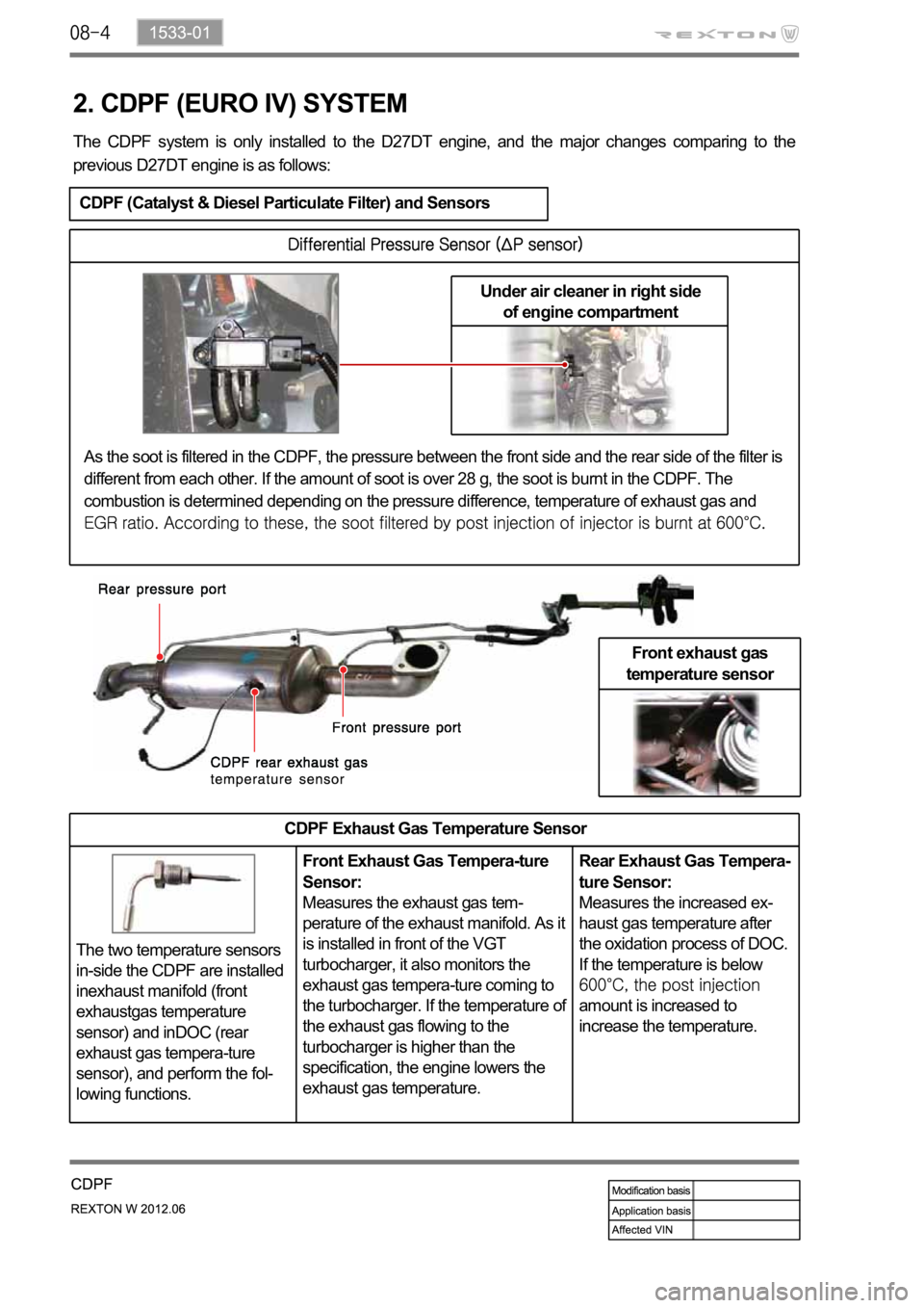
Under air cleaner in right side
of engine compartment
2. CDPF (EURO IV) SYSTEM
The CDPF system is only installed to the D27DT engine, and the major changes comparing to the
previous D27DT engine is as follows:
CDPF (Catalyst & Diesel Particulate Filter) and Sensors
Front exhaust gas
temperature sensor
CDPF Exhaust Gas Temperature Sensor
The two temperature sensors
in-side the CDPF are installed
inexhaust manifold (front
exhaustgas temperature
sensor) and inDOC (rear
exhaust gas tempera-ture
sensor), and perform the fol-
lowing functions.Front Exhaust Gas Tempera-ture
Sensor:
Measures the exhaust gas tem-
perature of the exhaust manifold. As it
is installed in front of the VGT
turbocharger, it also monitors the
exhaust gas tempera-ture coming to
the turbocharger. If the temperature of
the exhaust gas flowing to the
turbocharger is higher than the
specification, the engine lowers the
exhaust gas temperature.Rear Exhaust Gas Tempera-
ture Sensor:
Measures the increased ex-
haust gas temperature after
the oxidation process of DOC.
If the temperature is below
amount is increased to
increase the temperature.
As the soot is filtered in the CDPF, the pressure between the front side and the rear side of the filter is
different from each other. If the amount of soot is over 28 g, the soot is burnt in the CDPF. The
combustion is determined depending on the pressure difference, temperature of exhaust gas and
Page 226 of 600

2) System Composition for Soot Combustion
When the engine is running in low load range, the temperature of exhaust gas is decreased as the
amount of fuel supplied is decreased. To burn the soot filtered in the CDPF, the control system should
be installed to check the operating range and increase the temperature of exhaust gas by controlling the
amount of fuel supplied and intake air.
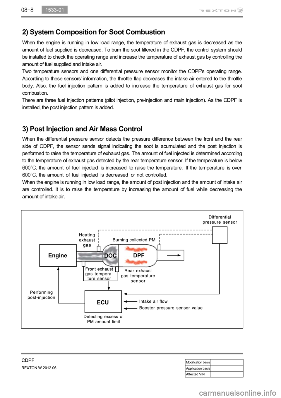
Two temperature sensors and one differential pressure sensor monitor the CDPF's operating range.
According to these sensors' information, the throttle flap decreases the intake air entered to the throttle
body. Also, the fuel injection pattern is added to increase the temperature of exhaust gas for soot
combustion.
There are three fuel injection patterns (pilot injection, pre-injection and main injection). As the CDPF is
installed, the post injection pattern is added.
3) Post Injection and Air Mass Control
When the differential pressure sensor detects the pressure difference between the front and the rear
side of CDPF, the sensor sends signal indicating the soot is acumulated and the post injection is
performed to raise the temperature of exhaust gas. The amount of fuel injected is determined according
to the temperature of exhaust gas detected by the rear temperature sensor. If the temperature is below
the amount of fuel injected is increased to raise the temperature. If the temperature is over
the amount of fuel injected is decreased or not controlled.
When the engine is running in low load range, the amount of post injection and the amount of intake ai
r
are controlled. It is to raise the temperature by increasing the amount of fuel while decreasing the
amount of intake air.
Page 261 of 600
0000-00
1) Service Interval
DescriptionDaily
inspectionWeekly
inspectionService interval
Engine oil & oil
filterInspection - EU Change every 20,000 km or 12 months
(The service interval should be
shortened under severe conditions)
General Change every 15,000 km or 12 months
(The service interval should be
shortened under severe conditions)
Coolant Inspection - Change every 200,000 km or 5 years
Air cleaner
element- Inspection Diesel EU Change every 20,000 km
(The service interval should
be shortened under severe
conditions)
General Clean every 7,500 km,
change every 15,000 km
(The service interval should
be shortened under severe
conditions)
Gasoline Clean every 15,000 km, replace every
60,000 km (The service interval should
be shortened under severe conditions)
Fuel filter - - EU Change every 40,000 km (Draining
water from fuel filter: whenever replacing
the engine oil)
General Change every 45,000 km (Draining
water from fuel filter: whenever replacing
the engine oil)
Page 267 of 600
0000-00
Hot water inlet pipe2 -
1 -
1 -
4 25~2.5Nm -
4 -
2 -
6 -
6 -
1 -
2 -
2 -
1 10~14Nm -
1 -
M8 10
-
M8 3
-
1
-
M8 1
-
T/C oil supply pipe M6(to block) 1
-
M6
(to turbocharger)1
-
T/C oil return pipe
2 -
(to turbocharger)2
-
EGR valve
3 -
EGR pipe bolt (to exhaust
manifold)
2 -
EGR pipe bolt (to EGR
cooler)
2 -
Name SizeNumbers of
fastenerTightening
torque (Nm)Note (total
tightening
torque)
Hot water inlet pipe
2 -
Alternator
1 -
1 -
Air conditioner
compressor
4 25~2.5Nm -
Air conditioner bracket
4 -
Intake manifold
2 -
6 -
Oil filter module
6 -
1 -
2 -
Knock sensor
2 -
Camshaft position sensor
1 10~14Nm -
T-MAP pressure sensor
1 -
Exhaust manifold M8 10
-
Turbocharger M8 3
-
T/C support bolt M8 1
-
Page 323 of 600
2210-01
3) DI Engine Fuel System Pressure Test
(1) Test device (Tool kit)
Device for high pressure
Device for low pressure
(2) Pre-check
Check-tighten fuel supply line
Check fuel level in fuel tank
Check air in fuel supply line (bubble in fuel supply line or fuel)
Check fuel supply line for leaks (low pressure and high pressure)
Check that specified fuel is used
Check fuel filter for contamination -
-
-
-
-
-
Page 328 of 600
(6) Low Pressure System Pressure Test
Inspection procedure
All wirings/connectors and fuel lines should be
connected and the engine should work
properly.
Prepare a special tool for low pressure test
and clean it thoroughly to prevent foreign
materials from entering. 1.
2.
Disconnect the key connector for fuel filter connection, and connect both connectors to the fuel filter
and hose. 3.
Start the engine and check visually for clogged low pressure fuel system, excessive air or air entry.
If the fuel flow is not sufficient or air is in the fuel, repair the leak area. 4.
5.
Page 341 of 600
1719-00
1. SPECIFICATION
Shorten the service interval under severe conditions such as driving on a dusty road or offroad. *
Unit Description Specification
Air cleaner elementFilter type Dry, filter element
Initial resistance Max. 300 mmAq
Service interval EU: Change every 20,000 km
GEN: Change every 15,000 km
Air cleaner assemblyWeight 103.9 kg
Operating temperature
IntercoolerCore material Aluminum
Size 614W x 192H x 30T
Core size 614W x 192H x 30T
Tank material Plastic (Molding)
Efficiency 80%
Page 360 of 600
1914-01
Turbine Side: Inflow of foreign materials from engine
Compressor Side: such as air filter, muffler and nut 3.