2012 SSANGYONG NEW REXTON wheel torque
[x] Cancel search: wheel torquePage 271 of 600

2. TIGHTENING TORQUE
Component SizeBolt
QuantitySpecified torque
(Nm)Remark
(Total torque)
Main bearing cap
10 Not re-usable
Connecting rod cap
850 to 80 Nm
Rear cover
6-
Oil pump
3-
Flywheel
860 to 100 Nm
Crankshaft center bolt
1660 to 720 Nm
Not re-usable
Oil pan
18-
2-
2-
2-
2-
HP pump main nut
1-
HP pump bolt
3-
Cylinder head
12 85Nm-
Camshaft cap
16-
4-
Exhaust stud bolt 10
-
Exhaust sprocket bolt
1-
Chain tensioner screw
bolt
1-
Coolant temperature
sensor1
-
Auto tensioner
1-
1-
Coolant pump
1-
Page 304 of 600

0000-00
Torque change curve of engine and drive shaft
Compression stroke Combustion stroke
Small changes from engine (k):
Damper increases the torque changes to clutchLarge changes from engine (j):
Damper decreases the torque changes to
transaxle by absorbing the impact
3) Operation
Compensating the irregular operation of engine: The secondary flywheel operates almost evenly so
does not cause gear noises
The mass of the primary flywheel is less than conventional flywheel so the engine irregularity
increases more (less pulsation absorbing effect).
Transaxle protection function: Reduces the torsional vibration to powertrain (transaxle) by reducing
the irregularity of engine. -
-
-
Page 305 of 600

4) Features
Reduced vibration noise from the powertrain by blocking the torsional vibrations
Enhanced vehicle silence and riding comforts: reduced engine torque fluctuation
Reduced shifting shocks
Smooth acceleration and deceleration -
-
-
-
5) Advantages
Improved torque response by using 3-stage type spring: Strengthens the torque response in all
ranges (low, medium, and high speed) by applying respective spring constant at each range.
Stable revolution of the primary and secondary wheel by using planetary gear: Works as auxiliary
damper against spring changes
Less heat generation due to no direct friction against spring surface: Plastic material is covered on
the spring outer surface
Increased durability by using plastic bushing (extends the lifetime of grease) -
-
-
-
6) Drive Plate
Drive plate receives the power from the start motor when starting the engine. With this, the drive plate
initially drives the power train system. And, it is connected to the torque converter to transfer the engine
torque to the power train system.
Trigger ring
Drive plate
Components
Page 372 of 600

1914-01
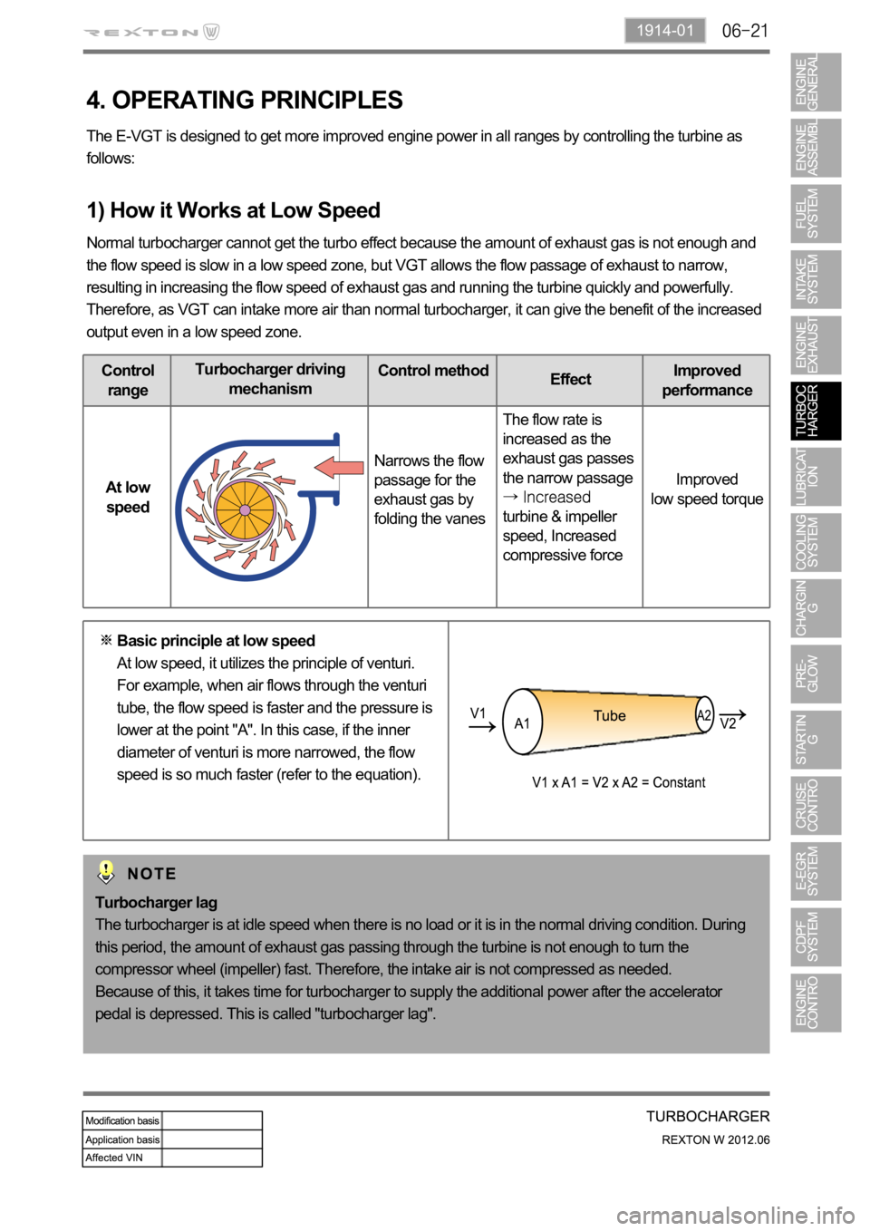
Control
rangeTurbocharger driving
mechanismControl method
EffectImproved
performance
At low
speedNarrows the flow
passage for the
exhaust gas by
folding the vanesThe flow rate is
increased as the
exhaust gas passes
the narrow passage
turbine & impeller
speed, Increased
compressive forceImproved
low speed torque
4. OPERATING PRINCIPLES
The E-VGT is designed to get more improved engine power in all ranges by controlling the turbine as
follows:
1) How it Works at Low Speed
Normal turbocharger cannot get the turbo effect because the amount of exhaust gas is not enough and
the flow speed is slow in a low speed zone, but VGT allows the flow passage of exhaust to narrow,
resulting in increasing the flow speed of exhaust gas and running the turbine quickly and powerfully.
Therefore, as VGT can intake more air than normal turbocharger, it can give the benefit of the increased
output even in a low speed zone.
Turbocharger lag
The turbocharger is at idle speed when there is no load or it is in the normal driving condition. During
this period, the amount of exhaust gas passing through the turbine is not enough to turn the
compressor wheel (impeller) fast. Therefore, the intake air is not compressed as needed.
Because of this, it takes time for turbocharger to supply the additional power after the accelerator
pedal is depressed. This is called "turbocharger lag". Basic principle at low speed
At low speed, it utilizes the principle of venturi.
For example, when air flows through the venturi
tube, the flow speed is faster and the pressure is
lower at the point "A". In this case, if the inner
diameter of venturi is more narrowed, the flow
speed is so much faster (refer to the equation).
Page 454 of 600

A fourth correction is made according to the pressure error.
This correction is used to reduce the injection timing advance when the pressure in the rail is higher
than the pressure demand.
A fifth correction is made according to the rate of EGR.
This correction is used to correct the injection timing advance as a function of the rate of exhaust gas
recirculation. -
-
<003a004b0048005100030057004b004800030028002a0035000300550044005700480003004c00510046005500480044005600480056000f00030057004b00480003004c0051004d004800460057004c0052005100030057004c0050004c0051004a000300
44004700590044005100460048000300500058005600570003[in fact be increased in order to
compensate for the fall in termperature in the cylinder.
A. Main Flow Control
The main flow represents the amount of fuel injected into the cylinder during the main injection. The pilot
flow represents the amount of fuel injected during the pilot injection.
The total fuel injected during 1 cycle (main flow + pilot flow) is determined in the following manner.
When the driver depress the pedal, it is his demand which is taken into account by the system in order
to determine the fuel injected.
When the driver release the pedal, the idle speed controller takes over to determine the minimum fuel
which must be injected into the cylinder to prevent the enigne from stalling. -
-
It is therefore the greater of these 2 values which is retained by the system. This value is then compared
with the lower flow limit determined by the ESP system.
As soon as the injected fuel becomes lower than the flow limit determined by the ESP system, the
antagonistic torque (engine brake) transmitted to the drive wheels exceeds the adherence capacity of
the vehicle and there is therefore a risk of the drive wheels locking.
The system thus chooses the greater of these 2 values (main flow & pilot flow) in order to prevent any
loss of control of the vehicle during a sharp deceleration.
As soon as the injected fuel becomes higher than the fuel limit determined by the ASR trajectory control
system, the engine torque transmitted to the wheels exceeds the adhesion capacity of the vehicle and
there is a risk of the drive wheels skidding. The system therefore chooses the smaller of the two values
in order to avoid any loss of control of the vehicle during accelerations.
The anti-oscillation strategy makes it possible to compensate for fluctuations in engine speed during
transient conditions. This strategy leads to a fuel correction which is added to the total fuel of each
cylinder.
A switch makes it possible to change over from the supercharge fuel to the total fuel according to the
state of the engine.
Until the stating phase has finished, the system uses the supercharged fuel.
Once the engine changes to normal operation, the system uses the total fuel. -
-
(5) Fuel Control
The main fuel is obtained by subtracting the pilot injection fuel from the total fuel.
A mapping determines the minimum fuel which can control an injector as a function of the rail pressure.
As soon as the main fuel falls below this value, the fuel demand changes to 0 because in any case the
injector is not capable of injecting the quantity demand.
Page 508 of 600

2) Cautions on Service Procedures
Before lifting up the vehicle with a lift, correctly support the lifting points.
When using a jack, park the vehicle on a level ground and place the wheel chocks under the
tires. Position the jack under the frame and lift up the vehicle and then support with chassis
stand before service work.
Make sure to disconnect the negative (-) cable from the battery to prevent any damage to
electric systems.
If you have to work on vehicle, cover the seats and floor with protection covers to avoid any
damage and contamination.
Brake fluid and anti-freeze can damage the painted surface of body. So carefully handle them
during service work.
To improve the efficiency of service work, use only recommended and specified tools.
Use only Ssangyong genuine spare parts.
Never reuse the cotter pin, gasket, O-ring, oil seal, lock washer and self-locking nut. Replace
them with new ones. If reused, normal functions cannot be maintained.
Store the disassembled parts as a set based on disassembly order and unit.
Pay particular attention not to miss or mix the fasteners.
If necessary, especially for inspection, clean the removed parts completely.
Apply the oil or grease on the running and sliding surfaces before installation. Use the specified
sealant and gasket to prevent leakage if necessary.
Tighten the fasteners with the specified tightening torque.
As a final stage of service work, check if the serviced system is working properly and the
problem has been eliminated clearly. 1.
2.
3.
4.
5.
6.
7.
8.
9.
10.
11.
12.
13.
14.
Page 591 of 600

0000-00
2) Cautions on Service Procedures
Before lifting up the vehicle with a lift, correctly support the lifting points.
When using a jack, park the vehicle on a level ground and place the wheel chocks under the
tires. Position the jack under the frame and lift up the vehicle and then support with chassis
stand before service work.
Make sure to disconnect the negative (-) cable from the battery to prevent any damage to
electric systems.
If you have to work on vehicle, cover the seats and floor with protection covers to avoid any
damage and contamination.
Brake fluid and anti-freeze can damage the painted surface of body. So carefully handle them
during service work.
To improve the efficiency of service work, use only recommended and specified tools.
Use only Ssangyong genuine spare parts.
Never reuse the cotter pin, gasket, O-ring, oil seal, lock washer and self-locking nut. Replace
them with new ones. If reused, normal functions cannot be maintained.
Store the disassembled parts as a set based on disassembly order and unit.
Pay particular attention not to miss or mix the fasteners.
If necessary, especially for inspection, clean the removed parts completely.
Apply the oil or grease on the running and sliding surfaces before installation. Use the specified
sealant and gasket to prevent leakage if necessary.
Tighten the fasteners with the specified tightening torque.
As a final stage of service work, check if the serviced system is working properly and the
problem has been eliminated clearly. 1.
2.
3.
4.
5.
6.
7.
8.
9.
10.
11.
12.
13.
14.