Page 196 of 600
0000-00
Schematic Diagram
Page 236 of 600
Page 239 of 600
0000-00
Coolant Flow in Engine
2. SCHEMATIC DIAGRAM
Cylinder block side
Cylinder head side
-
-
Page 243 of 600
Circuit Diagram
Specifications
Description Specification
Rated voltage DC 12V
Operating voltage DC 8~15V
Operating temperature
Relay operating voltage Over 6.5V
Relay OFF voltage OVER 1.5v
Relay coil resistance
Voltage drop Below 150Mv in each glow plug (Current: 16A)
Parasitic current Max. 1mA
Page 248 of 600
8510-23
2. CONFIGURATION
1) Circuit Diagram
The engine ECU detects the operating conditions of cruise control system, and monitors the braking
performance, vehicle speed, road conditions and ESP system operation. If the engine ECU determines
that there are not any problem to drive in cruise control mode, the vehicle can be operated by cruise
switch signals (decelerating, accelerating, cruising).
Page 274 of 600
0000-00
3. CHECK AND INSPECTION
1) Cylinder
(1) Compression pressure test
Specified value
Compression ratio16.5 : 1
Test condition
Compression pressureStandard32 bar
Minimum18 bar
Differential limit between cylindersMaximum 3 bar
The compression pressure test is to check the conditions of internal components (piston, piston ring,
intake and exhaust vale, cylinder head gasket). This test provides current engine operating status.
Before cranking the engine, make sure that the test wiring, tools and persons are keeping away
from moving components of engine (e.g., belt and cooling fan).
Park the vehicle on the level ground and apply the parking brake.
Do not allow anybody to be in front of the vehicle. -
-
-
Measurement
Disconnect the fuel rail pressure sensor connector to cut off the fuel injection.
Remove the air cleaner duct and glow plugs. -
-
-
Place the diagram sheet to compression
pressure tester and install it into the plug hole. 1.
Page 335 of 600
2210-01
1. OVERVIEW
The components in fuel system supply the fuel and generate the high pressure to inject the fuel to each
injector. They are controlled by the engine ECU.
The common rail fuel injection system consists of fuel tank, fuel line, low pressure line which supplies low
pressure fuel to the low pressure pump (including high pressure pump), common rail which distributes
and accumulates the high pressurized fuel from the fuel pump, high pressure line which connected to
the injector, and the engine control unit (ECU) which calculates the accelerator pedal position and
controls the overall performance of vehicle based on the input signals from various sensors.
1) Fuel Flow Diagram
Page 338 of 600

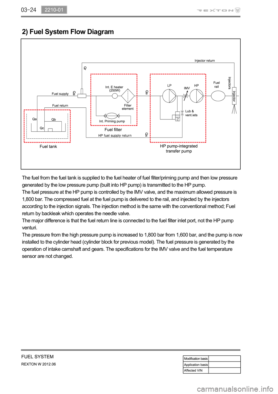
2) Fuel System Flow Diagram
The fuel from the fuel tank is supplied to the fuel heater of fuel filter/priming pump and then low pressure
generated by the low pressure pump (built into HP pump) is transmitted to the HP pump.
The fuel pressure at the HP pump is controlled by the IMV valve, and the maximum allowed pressure is
1,800 bar. The compressed fuel at the fuel pump is delivered to the rail, and injected by the injectors
according to the injection signals. The injection method is the same with the conventional method; Fuel
return by backleak which operates the needle valve.
The major difference is that the fuel return line is connected to the fuel filter inlet port, not the HP pump
venturi.
The pressure from the high pressure pump is increased to 1,800 bar from 1,600 bar, and the pump is now
installed to the cylinder head (cylinder block for previous model). The fuel pressure is generated by the
operation of intake camshaft and gears. The specifications for the IMV valve and the fuel temperature
sensor are not changed.