Page 230 of 600
2) Fuel Injection During CDPF Regeneration
3) Warning Lamp Related To CDPF
CDPF regeneration process (warning lamp NOT illuminated)
The CDPF system enters the regeneration mode when the
driving distance becomes approx. 600 to 1,200 km (may
differ by the driving condition and driving style). Then, the
engine ECU performs the CDPF regeneration operation.
However, the driver is not in-formed with this operation by an
y
engine warning lamp or vehicle signal, so he/she may not
detect this operation. The control logic at the post-injection
dur-ing the regeneration process is to increase the fuel
injection volume and control the intake air volume (by the
throttle body) in order to increase the tem-perature of the
exhaust gas. The driver may not feel any particular difference
from the vehicle.
No illumination
Page 261 of 600
0000-00
1) Service Interval
DescriptionDaily
inspectionWeekly
inspectionService interval
Engine oil & oil
filterInspection - EU Change every 20,000 km or 12 months
(The service interval should be
shortened under severe conditions)
General Change every 15,000 km or 12 months
(The service interval should be
shortened under severe conditions)
Coolant Inspection - Change every 200,000 km or 5 years
Air cleaner
element- Inspection Diesel EU Change every 20,000 km
(The service interval should
be shortened under severe
conditions)
General Clean every 7,500 km,
change every 15,000 km
(The service interval should
be shortened under severe
conditions)
Gasoline Clean every 15,000 km, replace every
60,000 km (The service interval should
be shortened under severe conditions)
Fuel filter - - EU Change every 40,000 km (Draining
water from fuel filter: whenever replacing
the engine oil)
General Change every 45,000 km (Draining
water from fuel filter: whenever replacing
the engine oil)
Page 267 of 600
0000-00
Hot water inlet pipe2 -
1 -
1 -
4 25~2.5Nm -
4 -
2 -
6 -
6 -
1 -
2 -
2 -
1 10~14Nm -
1 -
M8 10
-
M8 3
-
1
-
M8 1
-
T/C oil supply pipe M6(to block) 1
-
M6
(to turbocharger)1
-
T/C oil return pipe
2 -
(to turbocharger)2
-
EGR valve
3 -
EGR pipe bolt (to exhaust
manifold)
2 -
EGR pipe bolt (to EGR
cooler)
2 -
Name SizeNumbers of
fastenerTightening
torque (Nm)Note (total
tightening
torque)
Hot water inlet pipe
2 -
Alternator
1 -
1 -
Air conditioner
compressor
4 25~2.5Nm -
Air conditioner bracket
4 -
Intake manifold
2 -
6 -
Oil filter module
6 -
1 -
2 -
Knock sensor
2 -
Camshaft position sensor
1 10~14Nm -
T-MAP pressure sensor
1 -
Exhaust manifold M8 10
-
Turbocharger M8 3
-
T/C support bolt M8 1
-
Page 274 of 600
0000-00
3. CHECK AND INSPECTION
1) Cylinder
(1) Compression pressure test
Specified value
Compression ratio16.5 : 1
Test condition
Compression pressureStandard32 bar
Minimum18 bar
Differential limit between cylindersMaximum 3 bar
The compression pressure test is to check the conditions of internal components (piston, piston ring,
intake and exhaust vale, cylinder head gasket). This test provides current engine operating status.
Before cranking the engine, make sure that the test wiring, tools and persons are keeping away
from moving components of engine (e.g., belt and cooling fan).
Park the vehicle on the level ground and apply the parking brake.
Do not allow anybody to be in front of the vehicle. -
-
-
Measurement
Disconnect the fuel rail pressure sensor connector to cut off the fuel injection.
Remove the air cleaner duct and glow plugs. -
-
-
Place the diagram sheet to compression
pressure tester and install it into the plug hole. 1.
Page 340 of 600

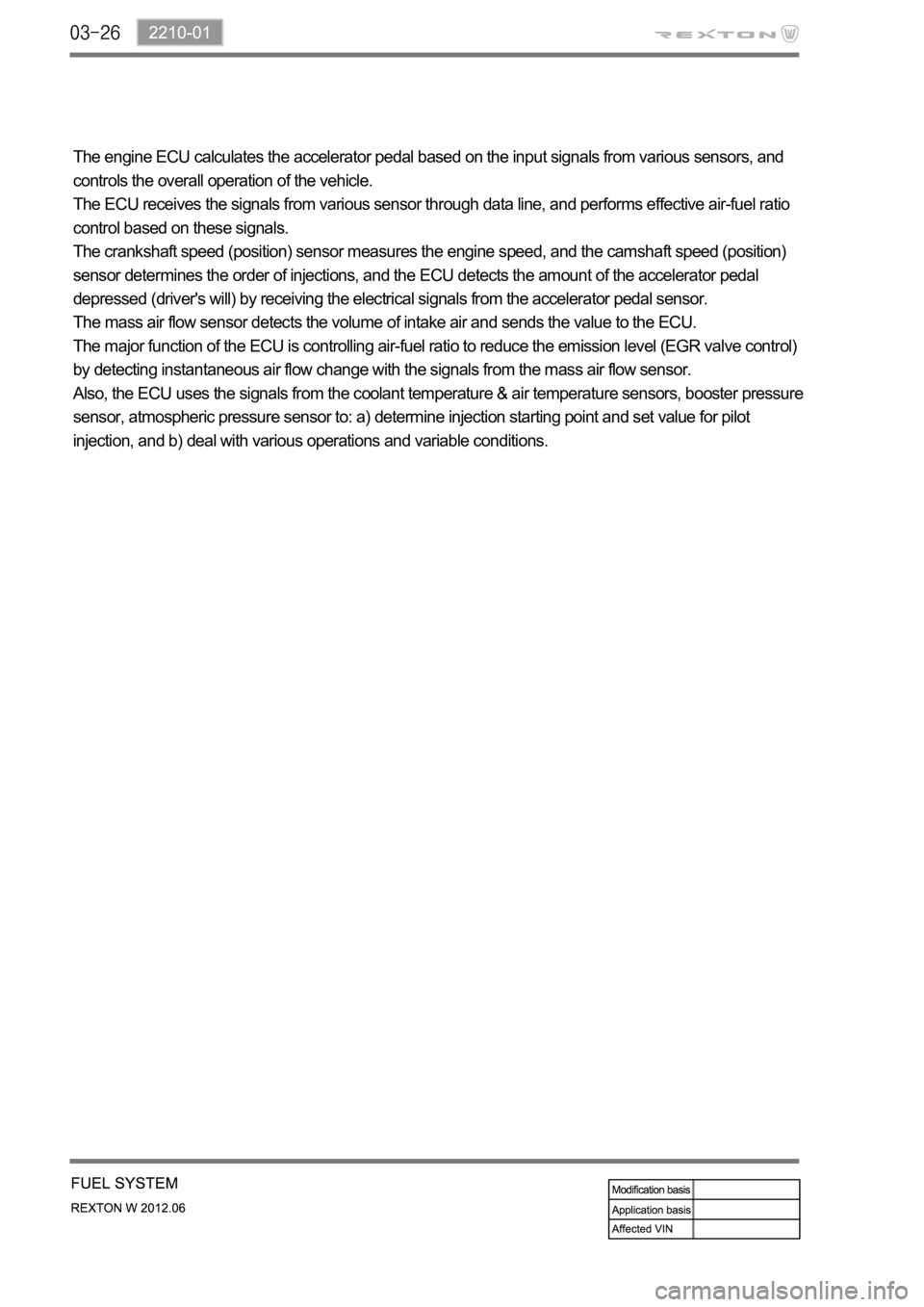
The engine ECU calculates the accelerator pedal based on the input signals from various sensors, and
controls the overall operation of the vehicle.
The ECU receives the signals from various sensor through data line, and performs effective air-fuel ratio
control based on these signals.
The crankshaft speed (position) sensor measures the engine speed, and the camshaft speed (position)
sensor determines the order of injections, and the ECU detects the amount of the accelerator pedal
depressed (driver's will) by receiving the electrical signals from the accelerator pedal sensor.
The mass air flow sensor detects the volume of intake air and sends the value to the ECU.
The major function of the ECU is controlling air-fuel ratio to reduce the emission level (EGR valve control)
by detecting instantaneous air flow change with the signals from the mass air flow sensor.
Also, the ECU uses the signals from the coolant temperature & air temperature sensors, booster pressure
sensor, atmospheric pressure sensor to: a) determine injection starting point and set value for pilot
injection, and b) deal with various operations and variable conditions.
Page 341 of 600
1719-00
1. SPECIFICATION
Shorten the service interval under severe conditions such as driving on a dusty road or offroad. *
Unit Description Specification
Air cleaner elementFilter type Dry, filter element
Initial resistance Max. 300 mmAq
Service interval EU: Change every 20,000 km
GEN: Change every 15,000 km
Air cleaner assemblyWeight 103.9 kg
Operating temperature
IntercoolerCore material Aluminum
Size 614W x 192H x 30T
Core size 614W x 192H x 30T
Tank material Plastic (Molding)
Efficiency 80%
Page 349 of 600

1719-00
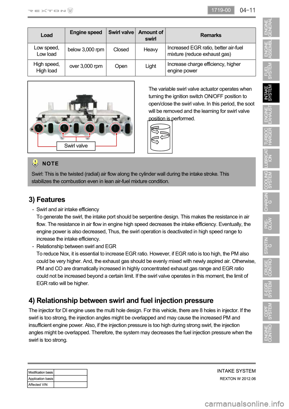
LoadEngine speed Swirl valveAmount of
swirlRemarks
Low speed,
Low loadbelow 3,000 rpm Closed HeavyIncreased EGR ratio, better air-fuel
mixture (reduce exhaust gas)
High speed,
High loadover 3,000 rpm Open LightIncrease charge efficiency, higher
engine power
The variable swirl valve actuator operates when
turning the ignition switch ON/OFF position to
open/close the swirl valve. In this period, the soot
will be removed and the learning for swirl valve
position is performed.
Swirl: This is the twisted (radial) air flow along the cylinder wall during the intake stroke. This
stabilizes the combustion even in lean air-fuel mixture condition.
Swirl valve
3) Features
Swirl and air intake efficiency
To generate the swirl, the intake port should be serpentine design. This makes the resistance in air
flow. The resistance in air flow in engine high speed decreases the intake efficiency. Eventually, the
engine power is also decreased, Thus, the swirl operation is deactivated in high speed range to
increase the intake efficiency.
Relationship between swirl and EGR
To reduce Nox, it is essential to increase EGR ratio. However, if EGR ratio is too high, the PM also
could be very higher. And, the exhaust gas should be evenly mixed with newly aspired air. Otherwise,
PM and CO are dramatically increased in highly concentrated exhaust gas range and EGR ratio
could not be increased beyond a certain limit. If the swirl valve operates in this moment, the limit of
EGR ratio will be higher. -
-
4) Relationship between swirl and fuel injection pressure
The injector for DI engine uses the multi hole design. For this vehicle, there are 8 holes in injector. If the
swirl is too strong, the injection angles might be overlapped and may cause the increased PM and
insufficient engine power. Also, if the injection pressure is too high during strong swirl, the injection
angles might be overlapped. Therefore, the system may decreases the fuel injection pressure when the
swirl is too strong.
Page 357 of 600

3) Inspection of Turbine
Thoroughly check the followings.
Must absolutely not operate the turbocharger with the compressor outlet and inlet opened as it could
damage the turbocharger or be hazardous during inspection.
Interference: In case where is trace of interference or smallest damage on the compressor wheel
means, most of times, that abrasion has occurred on the journal bearing. Must inspect after the
overhaul.
Oil Leakage: The reason for oil leakage at the compressor section is the air cleaner, clogged by
substances such as dust, causes the compressor inlet negative pressure. -
-
Rotating in high speed at no-load for extended period of time can cause oil leakage to the
compressor section as oil pressure within the center housing gets higher than pressure within the
compressor housing.
Overuse of engine break (especially in low gear) in down hill makes significantly low exhaust gas
energy compared to the time where great amount of air is required during idling conditions of the
engine. Therefore, amount of air in the compressor inlet increases but the turbocharge pressure is
not high, which makes negative a.
b.
No problem will occur with the turbocharger if above conditions are found in early stage but oil
leaked over long period of time will solidify at each section causing to breakout secondary defects.
Damages by foreign materials: In case where the compressor wheel is damaged by foreign materials
requires having an overhaul. At this time, it's necessary to check whether the foreign materials have
contaminated intake/exhaust manifold or inside of engine.