Page 184 of 600
0000-00
Knock sensor (one) and
water temperature sensor
Fuel rail sensor (common
rail)
1. LOCATION OF MAJOR SENSORS ON ENGINE
Major sensors and devices
InjectorGlow plugCommon rail
Camshaft position sensorBoost pressure sensor
Crankshaft position
sensor
HP pumpCommon rail
Injector
Turbocharger vacuum
modulator
Page 195 of 600
InjectorFuel filter and priming pump
8. LAYOUT OF FUEL SYSTEM
Components
IMV connector
Pressure sensor
in fuel rail
High pressure
fuel pipe
Fuel pipe
Common rail IMV connector
HP pump
Priming pumpFuel filter
Connector
Returned fuel
from HP pumpFuel filter
Fuel tank
HP pump
Fuel tank
Fuel return port
Low pressure fuel supply portVenturi
Fuel return portFuel temperature
sensor
IMV valve
IMV connectorHigh pressure fuel
supply port
(with orifice)
Page 201 of 600
Injector washer puller
2. SPECIAL SERVICE TOOLS
1) Using the Special Service Tools on Engine
Injector pullerGlow plug socket
HP remover/installerHigh pressure pipe
remover/installerCylinder head bolt wrench
Sealing caps
(fuel line)
Page 212 of 600

1. FUEL FLOW OF D20DT (EURO 4) ENGINE
According to input signals from various sensors, engine ECU calculates driver's demand (position of the
accelerator pedal) and then controls overall operating performance of engine and vehicle on that time. ECU
receives the signals from sensors via data line and then performs effective engine air-fuel ratio controls
based on those signals. Engine speed is measured by crankshaft speed (position) sensor and camshaft
speed (position) sensor determines injection order and ECU detects driver's pedal position (driver's
demand) through electrical signal that is generated by variable resistance changes in accelerator pedal
sensor. HFM (Hot Film Air Mass) sensor detects intake air volume and sends the signals to ECU.
Especially, the engine ECU controls the air-fuel ratio by recognizing instant air volume changes from air flow
sensor to decrease the emissions (EGR valve control). Furthermore, ECU uses signals from coolant
temperature sensor and air temperature sensor, booster pressure sensor and atmospheric pressure sensor
as compensation signal to respond to injection starting, pilot injection set values, various operations and
variables.
Page 213 of 600
0000-00
HP PumpFuel Line
Injector (7-way Injection and C3I Coding)Fuel filter Priming Pump
Common Rail
2. COMPONENTS OF FUEL SYSTEM
Fuel nozzle
holes (7)
Injector
Fuel pipe
High pressure fuel pip Fuel rail pressure sensor
Fuel filter
Connector
Priming
pump
Fuel from
HP pumpFuel filter
HP pumpFuel tank
Fuel tank
Common rail
Fuel return
port
Low pressure
fuel supply port
Venturi
High pressure
fuel supply port
(orifice included)
Fuel
temperature
sensor
IMV valve
Fuel return
port
IMV
connector
Page 214 of 600
3. HYDRAULIC CYCLE IN FUEL LINE
(TRANSFER AND HIGH PRESSURE LINE)
Page 226 of 600

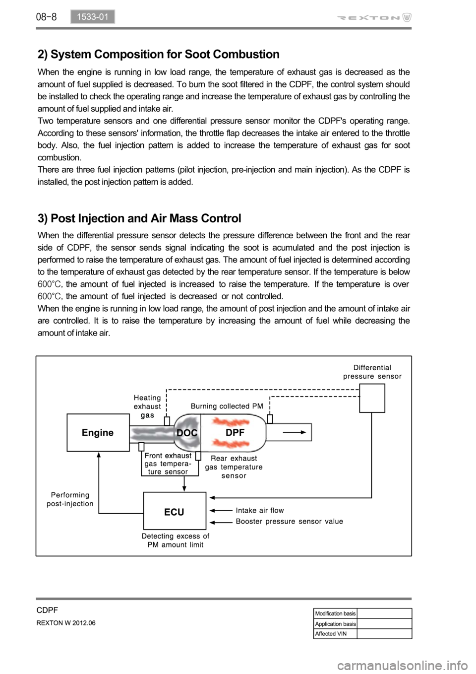
2) System Composition for Soot Combustion
When the engine is running in low load range, the temperature of exhaust gas is decreased as the
amount of fuel supplied is decreased. To burn the soot filtered in the CDPF, the control system should
be installed to check the operating range and increase the temperature of exhaust gas by controlling the
amount of fuel supplied and intake air.
Two temperature sensors and one differential pressure sensor monitor the CDPF's operating range.
According to these sensors' information, the throttle flap decreases the intake air entered to the throttle
body. Also, the fuel injection pattern is added to increase the temperature of exhaust gas for soot
combustion.
There are three fuel injection patterns (pilot injection, pre-injection and main injection). As the CDPF is
installed, the post injection pattern is added.
3) Post Injection and Air Mass Control
When the differential pressure sensor detects the pressure difference between the front and the rear
side of CDPF, the sensor sends signal indicating the soot is acumulated and the post injection is
performed to raise the temperature of exhaust gas. The amount of fuel injected is determined according
to the temperature of exhaust gas detected by the rear temperature sensor. If the temperature is below
the amount of fuel injected is increased to raise the temperature. If the temperature is over
the amount of fuel injected is decreased or not controlled.
When the engine is running in low load range, the amount of post injection and the amount of intake ai
r
are controlled. It is to raise the temperature by increasing the amount of fuel while decreasing the
amount of intake air.
Page 258 of 600
2. MAJOR COMPONENTS
Front view
Vacuum pump
Camshaft position sensor
Oil filter assembly
Power steering pump pulley
Oil pressure switch
Idler pulley No. 2
Water pump pulley
Alternator pulley
Auto tensioner
Idler pulley No. 1
A/C compressor pulley
Rear view
E-EGR valve
Fuel temperature sensor
Fuel HP pump assembly
Coolant temperature sensor
IMV valve Crankshaft position sensor
Isolation damper