Page 309 of 600
EnginePiston Cylinder bore
Part NO Marking NO.-
D20DTF 671 030 06 17 - -
671 037 07 01 A A
671 037 08 01 X X
671 037 09 01 B B
671 037 10 01 +5 -
671 037 11 01 +10 -
Selecting piston oversize
Top of piston Top of cylinder block
Page 312 of 600
0000-00
3) Crankshaft
(1) Overview
Crankshaft is installed on the cylinder block.
(2) Arrangement
Crankshaft main bearing upperCrankshaft main bearing upper
Upper thrust bearing
Crankshaft main bearing lowerCrankshaft main bearing lower
Lower thrust bearing
Crank pin journalMain journal
Page 313 of 600
Selection of bearing according to pin punch &
color
Mark Color Thickness of main
bearing
* Blue 66.500~66.506
** Yellow 66.506~66.513
*** Red 66.513~66.519
(3) Selection of crankshaft main bearing
Mark Color Thickness of main
bearing (mm)
V Violet +0.030
+0.025
W White +0.025
+0.020
R Red +0.020
+0.015
Y Yellow +0.015
+0.010
B Blue +0.010
+0.005
2.25
2.25
2.25
2.25
2.25
Bottom of cylinder block
Selection of upper main bearing
Mating surface of crankshaft sprocket
Selection of lower main bearing
Page 314 of 600
0000-00
4) Cylinder Block
(1) Overview
The major dimensions in D20DTR are similar to
D20DT engine. It has two mounting
bosses for knock sensor and meets the
requirements for EURO5 regulation.
(2) Layout
Right sideRight side
Expansion plug
Screw plug
Page 315 of 600
Left sideExpansion plug
(3) Features
For simple manufacturing, the crankcase blow-
by gas passage and the oil return hole are made
by casting on the cylinder block.
Page 316 of 600
0000-00
The bottom side of water jacket is desgined as sine wave to strengthen the structure of crankcase. The
main flow of coolant starts from outlet port of water pump and goes along the longitudinal direction of
engine. The coolant passage from cylinder head to inlet port of water pump is integrated in cylinder head.
The engine oil from oil pump is supplied to the main oil gallery through oil channel, oil filter module and
cross bore in cylinder block without using external pipes. This oil is supplied to main bearing, cylinder
head and MBU. And, it is sprayed to the chain through the chain tensioner connected to cross bore.
Crankcase cross bore for oil supply
Water jacket core
Page 334 of 600

(2) Di engine and its expected problems and remedies can be caused by
water in fuel
System supplement against paraffin separation
In case of Diesel fuel, paraffin, one of the elements, can be separated from fuel during winter and then
can stick on the fuel filter blocking fuel flow and causing difficult starting finally. Oil companies supply
summer fuel and winter fuel by differentiating mixing ratio of kerosene and other elements by region and
season. However, above phenomenon can be happened if stations have poor facilities or sell improper
fuel for the season. In case of DI engine, purity of fuel is very important factor to keep internal
preciseness of HP pump and injector.
Accordingly, more dense mesh than conventional fuel filter is used. To prevent fuel filter internal clogging
due to paraffin separation, SYMC is using fuel line that high pressure and temperature fuel injected by
injector returns through fuel filter to have an effect of built-in heater (see fuel system).
System supplement and remedy against water in fuel
As mentioned above, some gas stations supply fuel with excessive than specified water. In the
conventional IDI engine, excessive water in the fuel only causes dropping engine power or engine
hunting. However, fuel system in the DI engine consists of precise components so water in the fuel can
cause malfunctions of HP pump due to poor lubrication of pump caused by poor coating film during high
speed pumping and bacterization (under long period parking). To prevent problems can be caused by
excessive water in fuel, water separator is installed inside of fuel filter. When fuel is passing filter, water
that has relatively bigger specific gravity is accumulated on the bottom of the filter.
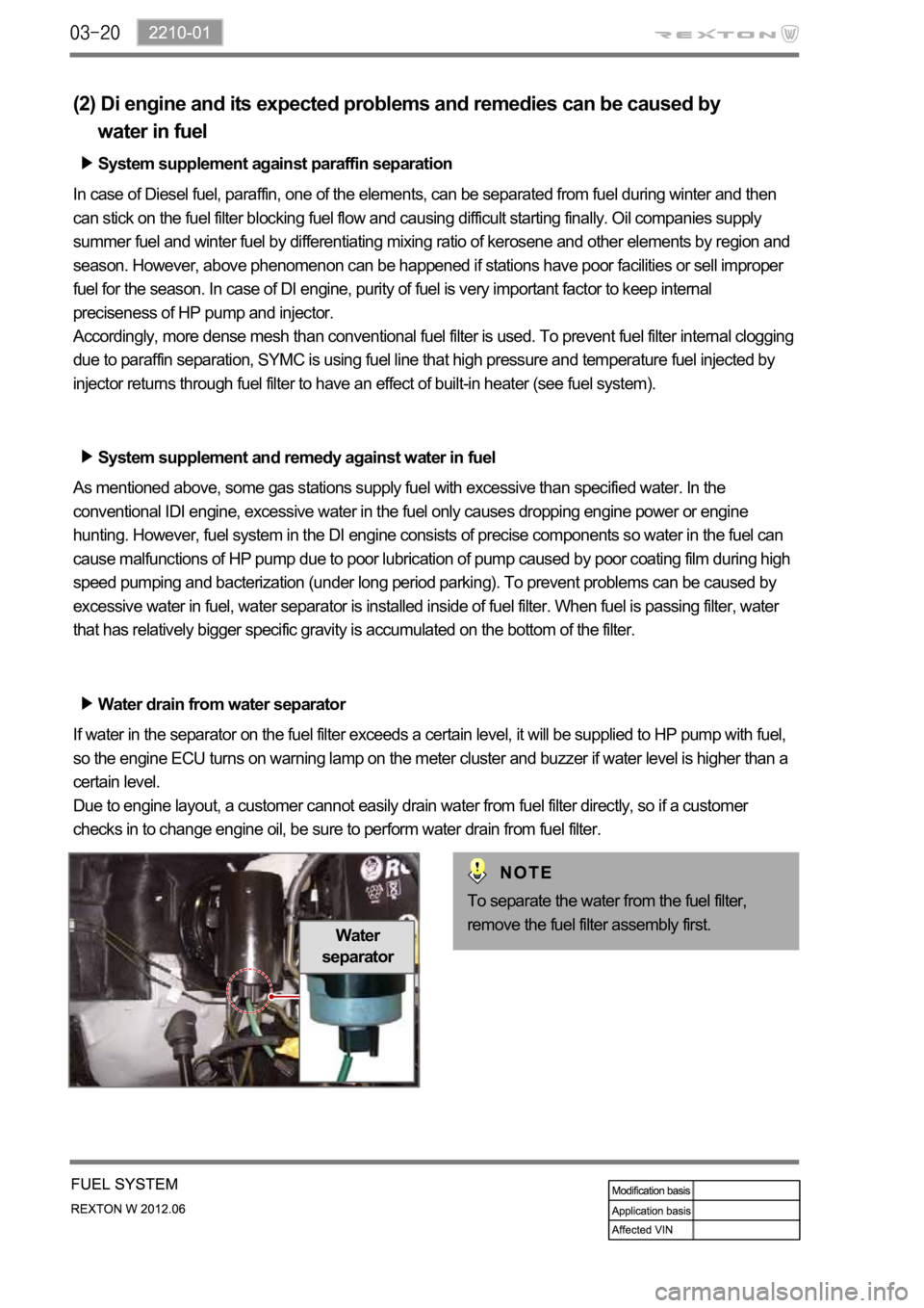
Water drain from water separator
If water in the separator on the fuel filter exceeds a certain level, it will be supplied to HP pump with fuel,
so the engine ECU turns on warning lamp on the meter cluster and buzzer if water level is higher than a
certain level.
Due to engine layout, a customer cannot easily drain water from fuel filter directly, so if a customer
checks in to change engine oil, be sure to perform water drain from fuel filter.
Water
separator
To separate the water from the fuel filter,
remove the fuel filter assembly first.
Page 338 of 600

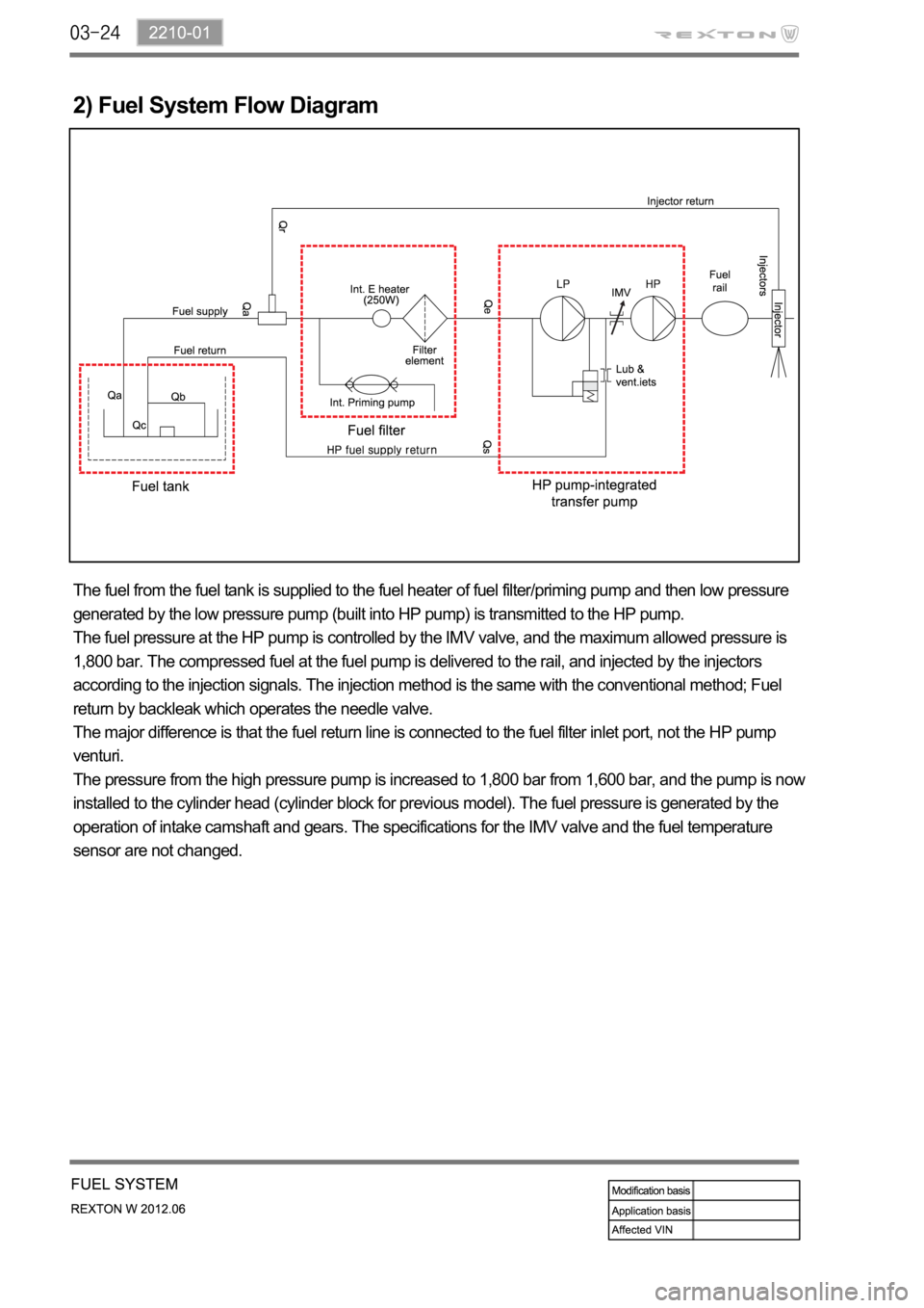
2) Fuel System Flow Diagram
The fuel from the fuel tank is supplied to the fuel heater of fuel filter/priming pump and then low pressure
generated by the low pressure pump (built into HP pump) is transmitted to the HP pump.
The fuel pressure at the HP pump is controlled by the IMV valve, and the maximum allowed pressure is
1,800 bar. The compressed fuel at the fuel pump is delivered to the rail, and injected by the injectors
according to the injection signals. The injection method is the same with the conventional method; Fuel
return by backleak which operates the needle valve.
The major difference is that the fuel return line is connected to the fuel filter inlet port, not the HP pump
venturi.
The pressure from the high pressure pump is increased to 1,800 bar from 1,600 bar, and the pump is now
installed to the cylinder head (cylinder block for previous model). The fuel pressure is generated by the
operation of intake camshaft and gears. The specifications for the IMV valve and the fuel temperature
sensor are not changed.