Page 105 of 222
 Owners Manual Information about convenience consumers and the amount of fuel con-sumed » operating instructions for Infotainment , chapter Setting vehicle systems
(CAR button) .
A maximum of three convenience con")
Information about convenience consumers and the amount of fuel con-sumed » operating instructions for Infotainment , chapter Setting vehicle systems
(CAR button) .
A maximum of three convenience consumers are displayed in the Infotainment
display- the top 3 in terms of energy consumption.
You can decide to switch off the consumers or to set them to a lower level to re-duce the level of fuel consumption.
Checking tyre inflation pressures
Tyres which are correctly inflated save fuel.
Always ensure the tyre inflation pressure is correct. If the inflation pressure is too
low, the tyres must overcome a higher rolling resistance. This will not only in-
crease fuel consumption but also tyre wear and the driving behaviour will worsen.
Always check the tyre inflation pressure when the tyres are cold.
Avoid unnecessary ballast
Transporting ballast costs fuel.
Every additional kilogram in weight increases the fuel consumption. We there-
fore recommend you do not travel with any unnecessary weight.
It is particularly in town traffic, when one is accelerating quite often, that the ve-
hicle weight will have a significant effect upon the fuel consumption. A rule of
thumb here is that an increase in weight of 100 kilograms will cause an increase
in fuel consumption of about 1 litre/100 kilometres.
At a speed of 100 - 120 km/h, a vehicle fitted with a roof rack cross member with-
out a load will use about 10 % more fuel than normal due to the increased aero- dynamic drag.
Regular servicing
A poorly tuned engine uses an unnecessarily high amount of fuel.
By having your vehicle regularly maintained by a ŠKODA specialist garage, you
create the conditions needed for driving economically. The maintenance state of your vehicle has a positive effect on traffic safety and value retention.
A poorly tuned engine can result in a fuel consumption which is 10 % higher than normal!
Check the oil at regular intervals, e.g. when filling up. Oil consumption is depend-
ent to a considerable extent on the load and speed of the engine. Oil consump-
tion could be as high as 0.5 litres/1 000 km depending on your style of driving.
It is quite normal that a new engine has a higher oil consumption at first, and rea- ches its lowest level only after a certain running in time. The oil consumption of anew vehicle can therefore only be correctly assessed after driving about5 000 km.
For the sake of the environment
■ Additional improvements to the fuel economy can be made by using synthetic
high-lubricity oils.■
Regularly check the ground under the vehicle. Have your vehicle inspected by a
ŠKODA specialist garage if you find any stains caused by oil or other fluids on the
floor.
Note
We recommend that your vehicle is serviced on a regular basis by a ŠKODA Part-
ner.
Environmental compatibility
Environmental protection has played a major role in the design, selection of mate-
rials and manufacture of your new ŠKODA. Particular emphasis has been placed
on the following points:
Design measures › Joints designed to be easily detached.
› Simplified disassembly due to the modular structure system.
› Improved purity of different classes of materials.
› Identification of all plastic parts in accordance with VDA Recommendation 260.
› Reduced fuel consumption and exhaust emission CO
2.
› Minimum fuel leakage during accidents.
› Reduced noise.
Choice of materials › Extensive use of recyclable material.
› Air conditioning filled with CFC-free refrigerant.
103Driving and the Environment
Page 106 of 222
 Owners Manual ›No cadmium.
› No asbestos.
› Reduction in the “vaporisation” of plastics.
Manufacture › Solvent-free cavity protection.
› Solvent-free protection of the vehicle for transportation from")
›No cadmium.
› No asbestos.
› Reduction in the “vaporisation” of plastics.
Manufacture › Solvent-free cavity protection.
› Solvent-free protection of the vehicle for transportation from the production
plant to the customer.
› The use of solvent-free adhesives.
› No CFCs used in the production process.
› Without use of mercury.
› Use of water-soluble paints.
Trade-in and recycling of old cars
ŠKODA meets the requirements of the brand and its products with regard to pro-
tecting the environment and the preserving resources. All new ŠKODA vehicles
can be utilized up to 95 % and always 1)
be returned.
In a lot of countries sufficient trade-in networks have been created, where you can trade-in your vehicle. After you trade-in your vehicle, you will receive a confir-
mation stating the recycling in accordance with environmental regulations.
Note
Detailed information about the trade-in and recycling of old cars is available from
a ŠKODA Partner.
Driving abroad
Introductory information
In certain countries it is also possible that the ŠKODA Partner network is limited
or has not been established yet. This is the reason why procuring certain spare
parts may be somewhat complicated and specialist garages may only be able to
make limited repairs.
ŠKODA in the Czech Republic and its importers are happy to provide information
about technical aspects of the vehicle, required maintenance work and possibili- ties for getting repairs done.
Unleaded petrol
A vehicle fitted with a petrol engine must always be refuelled with unleaded pet- rol » page 168 . Information regarding the locations of filling stations that offer
unleaded petrol is, for example, provided by the automobile associations.
Headlights
The low beam of your headlights is set asymmetrically. It illuminates the side of the road on which the vehicle is being driven to a greater extent.
When driving in countries in which the traffic drives on the other side of the roadthan in your home country, the asymmetrical low beam may dazzle oncoming
drivers. To prevent oncoming traffic from being dazzled, the headlights must be
adjusted by a ŠKODA Partner.
Headlights with Xenon lights are adjusted in the menu of the information dis-
play » operating instructions for Infotainment , chapter Setting vehicle systems
(CAR button) .
Note
Further information on adjusting the headlights is available from a ŠKODA Part-
ner.
Driving through water on the street
Fig. 98
Driving through water
1)
Subject to fulfilment of the national legal requirements.
104Using the system
Page 107 of 222
 Owners Manual The following must be observed to avoid damage to the vehicle when driving
through bodies of water (e.g. flooded roads):
› Determine the depth of the water when driving through bodies of water. The")
The following must be observed to avoid damage to the vehicle when driving
through bodies of water (e.g. flooded roads):
› Determine the depth of the water when driving through bodies of water. The
water level must fit around the strut on the side member as a maxi-mum » Fig. 98 ;
› Do not drive any faster than at a walking speed. At a higher speed, a water
wave can form in front of the vehicle which can cause water to penetrate into the air induction system of the engine or into other parts of the vehicle;
› Never stop in the water, do not reverse and do not switch the engine off;
› Deactivate the START-STOP system before driving through water
» page 121.WARNING■
Driving through water, mud, sludge etc. can reduce the braking power and
extend the braking distance – risk of accident!■
Avoid abrupt and sudden braking immediately after water crossings.
■
After driving through bodies of water, the brakes must be cleaned and dried
as soon as possible by intermittent braking. Only apply the brakes for the pur-
pose of drying and cleaning the brake discs if the traffic conditions permit this.
Do not place any other road users in jeopardy.
CAUTION
■ When driving through bodies of water, some parts of the vehicle such as the
engine, gearbox, chassis or electrics can be severely damaged.■
Oncoming vehicles can generate water waves which can exceed the permissible
water level for your vehicle.
■
Potholes, mud or rocks can be hidden under the water making it difficult or im-
possible to drive through the body of water.
■
Do not drive through salt water. The salt can lead to corrosion. Any vehicle parts
that have come into contact with salt water must be rinsed immediately with
fresh water.
Note
After driving through a body of water, we recommend that the vehicle is checked
by a ŠKODA specialist garage.
105Driving and the Environment
Page 108 of 222
 Owners Manual Towing a trailer
Towing device
Introduction
This chapter contains information on the following subjects:
Description
106
Setting the ready position
107
Installing the ball rod
107
Check proper atta")
Towing a trailer
Towing device
Introduction
This chapter contains information on the following subjects:
Description
106
Setting the ready position
107
Installing the ball rod
107
Check proper attachment
108
Removing the ball rod
108
Operation and maintenance
109
If your vehicle has already been factory-fitted with a towing device or is fitted
with a towing device from ŠKODA Original Accessories, then it meets all of the
technical requirements and national legal provisions for towing a trailer.
Your vehicle is fitted with a 13-pin power socket for the electrical connection be-tween the vehicle and trailer. If the trailer that is to be towed has a 7-pin connec-
tor , you can use a suitable adapter from ŠKODA Original Accessories.
The maximum trailer drawbar load is 75 kg/h.
WARNING■
Before each time you make a journey when using the ball rod, check that it
is seated correctly and is secured in the mounting recess.■
Do not operate the ball rod if it is not correctly inserted in the mounting re-
cess.
■
Do not operate the towing device if it is damaged or incomplete.
■
Do not perform any modifications or changes to the towing device.
■
Never release the ball rod while the trailer is still coupled.
CAUTION
■ If there is an error in the trailer lighting system, check the fuses in the fuse box
in the dashboard. » page 200■
Handle the ball rod carefully to avoid damaging the paintwork on the bumper.
Note■
After coupling the trailer and connecting up the power socket, check the rear
lights on the trailer to ensure they work.■
If you have any questions, please contact a ŠKODA Partner.
Description
Fig. 99
Carrier of the towing device/ball rod
First read and observe the introductory information and safety warn-
ings
on page 106.
The ball rod can be removed and can be found in the spare wheel well or in a
compartment for the spare wheel in the boot » page 188.
Explanation of graphic
13-pin power socket
Safety eye
Mounting recess
Cap
Dust cap
Ball rod
Operating lever
Lock cap
Trigger pin
Keys
Locking ball
1234567891011106Using the system
Page 109 of 222
 Owners Manual NoteIf you lose the key, please get in touch with a ŠKODA Partner.
Setting the ready position
Fig. 100
Setting the ready position/ready position
First read and observe the introductory informatio")
NoteIf you lose the key, please get in touch with a ŠKODA Partner.
Setting the ready position
Fig. 100
Setting the ready position/ready position
First read and observe the introductory information and safety warn-
ings
on page 106.
Before installing always adjust the ball rod in the ready position.
›
Turn the key so that its red mark
1
» Fig. 100 becomes visible.
›
Grab the ball rod underneath the protective cap
2
.
›
Press the trigger pin
3
as far as the stop in the direction of the arrow - at the
same time push the lever
4
downwards as far as it will go in the direction of
the arrow.
The lever remains locked in this position.
CAUTION
In the ready position, the key cannot be removed nor turned into a different posi-
tion.
Installing the ball rodFig. 101
Insert the ball rod/lock up the lock, and put the lock cover on
First read and observe the introductory information and safety warn- ings
on page 106.
›
Pull of the cap
4
» Fig. 99 on page 106 downwards.
›
Set the ball rod into the ready position.
›
Grab the ball rod from underneath » Fig. 101 and insert into the mounting re-
cess until it audibly clicks » .
The lever
1
» Fig. 101 automatically turns upwards and the trigger pin
2
comes
out (its red and green part is visible) » .
If the lever
1
does not turn automatically, or if the trigger pin
2
does not come
out, remove the ball rod from the mounting recess by turning the lever down-
wards as far as it can go. Clean the wedge surfaces on the ball rod and the
mounting recess.
›
Lock the lock on the operating lever by turning the key by 180° to the right (see
green marking
3
is visible) and remove the key in the direction of the arrow.
›
Insert the cap
4
on the lock in the direction of the arrow » .
›
Check the ball rod for proper attachment » page 108.
WARNING■
Keep your hands outside the lever's range of motion when attaching the ball
rod- risk of finger injuries!■
Never attempt to pull the operating lever violently upwards to turn the key.
Doing so would mean the ball rod is not attached correctly! 107Towing a trailer
Page 110 of 222
 Owners Manual CAUTION■After removing the key, always replace the cap on the lock of the operating lev-
er - risk the lock may get contaminated.■
Keep the mounting recess of the towing device clean at all times")
CAUTION■After removing the key, always replace the cap on the lock of the operating lev-
er - risk the lock may get contaminated.■
Keep the mounting recess of the towing device clean at all times. Such dirt pre-
vents the ball rod from being attached securely!
■
After removing the ball rod, always place the cap on the mounting recess.
Check proper attachment
Fig. 102
Check the proper attachment of
the ball rod
First read and observe the introductory information and safety warn- ings on page 106.
Before each use of the ball rod, check that it is attached properly.
Check whether:
› the lever
1
is right at the top
» Fig. 102;
› the trigger pin
2
is completely exposed (both its red and green part is visible);
› the key has been removed;
› the cap
3
is on top of the lock of the operating lever;
› after “shaking” it heavily, the ball rod does not come attached from the mount-
ing recess.
WARNINGDo not use the towing device unless the ball rod was properly locked!
Removing the ball rodFig. 103
Unlock the operating lever of the ball rod/removing the ball rod
First read and observe the introductory information and safety warn-
ings
on page 106.
›
Remove the cap
1
» Fig. 103 from the lock on the ball rod in the direction of
the arrow.
›
Unlock the lock on the operating lever by turning the key 180° to the left so that
the red marking
2
becomes visible.
›
Grab hold of the ball rod from underneath.
›
Press the trigger pin
3
as far as the stop in the direction of the arrow - at the
same time push the lever
4
downwards as far as it will go in the direction of
the arrow.
The ball rod is released in this position and falls freely into the hand. If it does not
fall freely into the hand, use your other hand to push it upwards.
At the same time, the ball rod latches into the ready position and is thus ready to
be re-inserted into the mounting recess »
.
›
Place the cap
4
» Fig. 99 on page 106 on the mounting recess.
WARNINGNever allow the ball rod to remain unsecured in the boot. This could cause
damage in a sudden braking manoeuvre and put the safety of the occupants
at risk! 108Using the system
Page 111 of 222
 Owners Manual CAUTION■If the lever is held firm and not pushed downwards as far as it can go, it will go
back up after the ball rod is removed and will not latch into the ready position.
The ball rod then needs t")
CAUTION■If the lever is held firm and not pushed downwards as far as it can go, it will go
back up after the ball rod is removed and will not latch into the ready position.
The ball rod then needs to be brought into this position before the next time it is installed.■
Stow the ball rod in the ready position with the key inserted in the box. When
doing so, make the side opposite to the inserted key face downwards - risk of damaging the key!
■
Do not use excessive force when handling the operating lever (e.g. do not climb
on it)!
Note
Remove any dirt from the ball rod before stowing it away in the box with the ve-
hicle tool kit.
Operation and maintenance
First read and observe the introductory information and safety warn-ings
on page 106.
Seal the mounting recess with the cap to prevent any ingress of dirt.
Always check the ball head before hitching a trailer. Use a suitable lubricating grease where necessary.
Include the protective cap when stowing away the ball rod to protect the boot
from getting contaminated.
In the event of dirt, clean the surfaces of the mounting recess and treat with a
suitable preservative.
CAUTION
Apply lubricating grease to the upper part of the mounting recess. Make sure you
do not remove any grease.
Loading a trailer
The vehicle/trailer combination must be balanced. whereby the maximum permis- sible drawbar load must be utilised. If the drawbar load is too low, it jeopardisesthe performance of the vehicle/trailer combination.
Distribution of the load
Distribute the load in the trailer in such a way that heavy items are located as
close to the axle as possible. Secure the items from slipping.
The distribution of the weight is very poor if your vehicle is unladen and the trail-
er is laden. Drive at a particularly low speed if you cannot avoid driving with this
combination.
Tyre pressure
Correct the tyre inflation pressure on your vehicle for a “full load” » page 182,
Tyre life .
Trailer load
The permissible trailer load must not be exceeded under any circumstan-
ces » page 207 , Technical data .
The trailer loads specified apply only to altitudes up to 1 000 metres above mean
sea level.
The engine output falls as the height increases, as does the ability to climb.
Therefore, for every additional 1 000 m in height (every one begun), the maximum
permissible towed weight must be reduced by 10 %.
The towed weight comprises the actual weight of the (loaded) towing vehicle and the (loaded) trailer.
The trailer and drawbar load information on the type plate of the towing device are merely test data for the towing device. The vehicle-specific values are de-tailed in the vehicle documents.WARNING■ Do not exceed the maximum permissible axle and drawbar load and the
maximum permissible total or towed weight of the vehicle and the trailer -
risk of accident and serious injuries!■
Always drive particularly carefully with the trailer.
■
Slipping loads can significantly affect the stability and safety of the vehicle/
trailer combination - risk of accident and serious injuries!
109Towing a trailer
Page 112 of 222
 Owners Manual Driving with a trailerFig. 104
Swivel out the 13-pin power
socket
›
Before hitching the trailer to the vehicle, hold on to the 13-pin power socket in the area
A
» Fig. 104 and swivel it out in")
Driving with a trailerFig. 104
Swivel out the 13-pin power
socket
›
Before hitching the trailer to the vehicle, hold on to the 13-pin power socket in the area
A
» Fig. 104 and swivel it out in the direction of the arrow.
›
Remove the protective cap
5
» Fig. 99 on page 106 upwards before hitching
the trailer to the vehicle.
Safety eye
The purpose of the safety eye
2
» Fig. 99 on page 106 is to attach the break-
away cable of the trailer.
When attaching the breakaway cable to the safety eye, it must sag freely in all
trailer positions (sharp bends, in reverse, etc.).
Exterior mirrors
You have to have additional exterior mirrors fitted if you are not able to see the
traffic behind the trailer with the standard rear-view mirrors. The national legal
requirements must be observed.
Headlights
The headlight settings must be checked before starting a journey with a coupled
trailer. If necessary, adjust the settings with the headlight beam adjust-
ment » page 44 .
Driving speed
For safety reasons, do not drive faster than 80 km/h when hitching a trailer.
Immediately reduce your speed as soon as even the slightest swaying of the trail- er is detected. Never attempt to stop the trailer from “swaying” by accelerating.
Brakes
Apply the brakes in good time! If the trailer is fitted with a trailer brake, apply the
brakes gently at first, then brake firmly. This will avoid brake jolts resulting from
the trailer wheels locking.
On downhill sections shift down a gear in good time to also use the engine as a
brake.
Trailer stabilisation
The trailer stabilisation is an extension of the stabilisation control that works in
conjunction with the counter-steering assistance to reduce the amount the trail-
er "sways".
After turning on the ignition, the ESC warning light in the instrument cluster
lights up for about 2 seconds longer than the ABS warning light.
Prerequisites: › The towing device is assembled or retrofitted ex works;
› The ESC system is active. The warning light
or in the instrument cluster is
not illuminated;
› The trailer is electrically connected to the towing vehicle by means of the trailer
socket;
› The speed is higher than approx. 60 km/h;
› The trailer has a fixed drawbar;
› The ESC system works for both braked and unbraked trailers.
A trailer is connected to the anti-theft alarm system, when: › the vehicle is factory-fitted with an anti-theft alarm system and a towing de-
vice;
› the trailer is electrically connected to the towing vehicle by means of the trailer
socket;
› the electrical system of the vehicle and trailer is fully functional;
› the vehicle is locked with the car key and the anti-theft alarm system is activa-
ted.
When the vehicle is locked, the alarm is activated as soon as the electrical con-
nection to the trailer is interrupted.
Always switch off the anti-theft alarm system before a trailer is connected/dis- connected » page 35, Anti-theft alarm system .
Engine overheating
If the needle for the coolant temperature gauge moves into the right-hand area or the red area of the scale, the speed must be reduced immediately.
Stop and switch off the engine if the warning light
in the instrument cluster
lights up. Wait a few minutes and check the level of coolant » page 174.
The following guidelines must be observed » page 15, Coolant temperature/cool-
ant level
.
The coolant temperature can be reduced by switching on the heating. 110Using the system
 1
1 2
2 3
3 4
4 5
5 6
6 7
7 8
8 9
9 10
10 11
11 12
12 13
13 14
14 15
15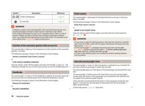 16
16 17
17 18
18 19
19 20
20 21
21 22
22 23
23 24
24 25
25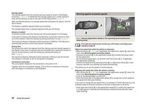 26
26 27
27 28
28 29
29 30
30 31
31 32
32 33
33 34
34 35
35 36
36 37
37 38
38 39
39 40
40 41
41 42
42 43
43 44
44 45
45 46
46 47
47 48
48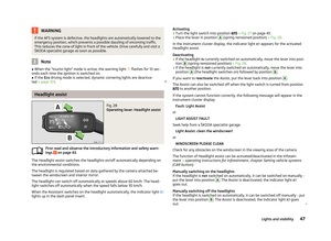 49
49 50
50 51
51 52
52 53
53 54
54 55
55 56
56 57
57 58
58 59
59 60
60 61
61 62
62 63
63 64
64 65
65 66
66 67
67 68
68 69
69 70
70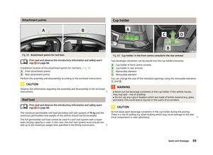 71
71 72
72 73
73 74
74 75
75 76
76 77
77 78
78 79
79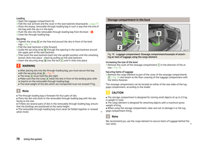 80
80 81
81 82
82 83
83 84
84 85
85 86
86 87
87 88
88 89
89 90
90 91
91 92
92 93
93 94
94 95
95 96
96 97
97 98
98 99
99 100
100 101
101 102
102 103
103 104
104 105
105 106
106 107
107 108
108 109
109 110
110 111
111 112
112 113
113 114
114 115
115 116
116 117
117 118
118 119
119 120
120 121
121 122
122 123
123 124
124 125
125 126
126 127
127 128
128 129
129 130
130 131
131 132
132 133
133 134
134 135
135 136
136 137
137 138
138 139
139 140
140 141
141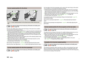 142
142 143
143 144
144 145
145 146
146 147
147 148
148 149
149 150
150 151
151 152
152 153
153 154
154 155
155 156
156 157
157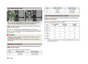 158
158 159
159 160
160 161
161 162
162 163
163 164
164 165
165 166
166 167
167 168
168 169
169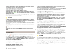 170
170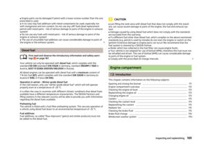 171
171 172
172 173
173 174
174 175
175 176
176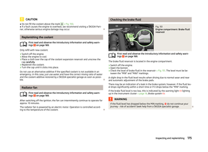 177
177 178
178 179
179 180
180 181
181 182
182 183
183 184
184 185
185 186
186 187
187 188
188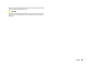 189
189 190
190 191
191 192
192 193
193 194
194 195
195 196
196 197
197 198
198 199
199 200
200 201
201 202
202 203
203 204
204 205
205 206
206 207
207 208
208 209
209 210
210 211
211 212
212 213
213 214
214 215
215 216
216 217
217 218
218 219
219 220
220 221
221