Page 169 of 196

■
One should be constantly vigilant not to allow impermissibly high towing forces
or jerky loadings. There is always a risk of excessive stresses and damage result-
ing at the points to which you attach the tow rope or tow bar when you attempt
to tow a vehicle which is not standing on a paved road.
■ Attach the tow rope or the tow bar to the towing eyes or to the detachable ball
head of the towing device » page 167
or » page 167.Note
■ We recommend using a tow rope from
ŠKODA Original Accessories available
from a ŠKODA Service Partner. ■ Towing another vehicle requires a certain amount of practice. Both drivers
should be familiar with the particular points about towing a vehicle. Unskilled
drivers should not attempt to tow in another vehicle or to be towed in. ■ When towing, respect the national legal provisions, especially those which re-
late to the identification of the towing vehicle and the vehicle being towed. ■ The tow rope must not be twisted as it may in certain circumstances result in
the front towing eye being unscrewed out of your vehicle. ÐFront towing eye
Fig. 140
Front bumper: Cap/installing the towing eye
First read and observe the introductory information and safety warn-
ings on page 166.
Remove the cap carefully as follows.
›
Press on the left half of the cap in the area of the arrow
» Fig. 140 - .
› Remove the cap from the front bumper.
ä ›
Screw in the towing eye by hand to the left up to the stop
» Fig. 140 - . For
tightening purposes, we recommend, for example, using the wheel wrench,
towing eye from another vehicle or a similar object that can be pushed through
the eye.
› In order to reinstall the cap after screwing out the towing eye, insert it in the
mounts and then press on the right side of the cap. The cap must engage firmly. CAUTION
The towing eye must always be screwed in fully and firmly tightened, otherwise
the towing eye can tear when towing in or tow-starting. Ð Rear towing eye
Fig. 141
Rear towing eye
First read and observe the introductory information and safety warn-
ings on page 166.
The rear towing eye is located below the rear bumper on the right
»
Fig. 141. Ð ä
167
Do-it-yourself
Page 170 of 196

Fuses and light bulbs
Fuses
ä
Introduction
This chapter contains information on the following subjects:
Fuses in the dash panel 169
Fuses in the engine compartment 170
Individual electrical circuits are protected by fuses.
› Before replacing a fuse, switch off the ignition and the appropriate consumer
› Find out which fuse belongs to the component that is not operat-
ing » page 169, Fuses in the dash panel or » page 170, Fuses in the engine
compartment .
› Take the plastic clip out of its fixture in the cover of the fuse box, place it on the
relevant fuse and pull it out.
› A blown fuses is recognisable by the molten metal strip. Replace the faulty fuse
with a new one of the
same amperage.
Colour coding of fuses Colour Maximum amperage
light brown 5
dark brown 7.5
red 10
blue 15
yellow 20
white 25
green 30WARNING
Always read and observe the warnings before completing any work in the en-
gine compartment » page 138, Engine compartment . CAUTION
■ Never “repair” fuses and also do not replace them with a fuse of a higher am-
perage - risk of fire! This may also cause damage at another part of the electrical
system.
■ Have the electrical system checked as quickly as possible by a ŠKODA specialist
garage if a newly inserted fuse blows again after a short time. Note
■ We recommend always carrying replacement fuses in the vehicle. A box of re-
placement fuses can be purchased from
ŠKODA Original Accessories.
■ Multiple fuses may exist for a single power consuming device.
■ Multiple power consuming devices can share a single fuse. Ð
168 Do-it-yourself
Page 171 of 196

Fuses in the dash panel
Fig. 142
Underside of the dash panel:
Distribution board cover. Fig. 143
Schematic representation of the fuse box for vehicles with left-
hand steering/right-hand steering
First read and observe the introductory information and safety warn-
ings on page 168.
The fuses are located on the left side of the dash panel behind a cover.
›
Carefully remove the cover in the direction of the arrow
» Fig. 142.
› After the fuse has been replaced, replace the cover in the dash panel in the op-
posite direction of the arrow so that the guide lugs are guided into the open-
ings of the dash panel. Close the cover until it clicks into place.
Fuse assignment in the dash panel No. Power consumer
1 S-contact
2 START-STOP, air-conditioning system
3 Instrument cluster, headlamp beam adjustment ä No. Power consumer
4 Control unit for ABS, button for START STOP5 Petrol engine: Speed regulating system
6 Reversing light (manual gearbox) 7 Ignition, engine control unit, automatic gearbox
8 Brake pedal switch, clutch pedal switch
9 Operating controls for the heating, control unit for air conditioning sys-
tem, parking aid, control unit for cornering lights, radiator fan, washing
nozzles
10 Windscreen Wiper and Washer System 11 Mirror adjustment
12 Control unit for trailer detection
13 Control unit for automatic gearbox
14 Motor for halogen projector headlights with cornering light function 15 PDA navigation system
16 Electrohydraulic power steering 17 START-STOP (radio), daylight driving light
18 Mirror heater 19 S-contact
20 Alarm 21 Reversing light, fog lights with the function CORNER
22 Operating controls for the heating, control unit for air conditioning sys-
tem, parking aid, mobile phone, instrument cluster, steering angle
sender, ESC, vehicle voltage control unit, multifunction steering wheel
23 Interior lighting, storage compartment and luggage compartment, side
lights
24 Central control unit 25 Seat heaters
26 Rear window wiper 27 Telephone preinstallation
28 Petrol engine: AKF valve, Diesel engine: Control flap 29 Injection, coolant pump
30 Fuel pump, ignition, Cruise control system, operation of PTC relay 31 Lambda probe £ 169
Fuses and light bulbs
Page 172 of 196

No. Power consumer
32 High pressure fuel pump, pressure valve
33 Engine control unit
34 Engine control unit, vacuum pump 35 Power supply of ignition lock
36 Main beam 37 Rear fog light, DC/DC converter START-STOP
38 Fog lights 39 Air blower for heating
40-41 Not assigned 42 Rear window heater
43 Horn
44 Windscreen wipers 45 Central control unit for convenience system
46 Engine control unit, fuel pump 47 Cigarette lighter, power socket in the luggage compartment
48 ABS, START-STOP (DC/DC) converter ESP 49 Turn signal lights, brake lights50 START-STOP (DC/DC) converter infotainment, radio 51 Electrical power window (front and rear) - left side
52 Electrical power window (front and rear) - right side
53 Parking light = left side, electrical sliding/tilting roof
54 START-STOP (instrument cluster), alarm 55 Control unit for automatic gearbox
56 Headlight cleaning system, parking light - right side 57 Left low beam, headlight range adjustment
58 Low beam on the right Ð Fuses in the engine compartment
Fig. 144
Vehicle battery: Distribution board cover. Fig. 145
Schematic representation of
fuse box in engine compartment
First read and observe the introductory information and safety warn-
ings on page 168.
›
Press together the circlips in the fuse box cover at the same time in the direc-
tion of arrow A
» Fig. 144
and remove the cover in the direction of arrow B
.
› Release the fixtures in the openings C
using a flat screwdriver and fold the
cover upwards in direction of arrow D
.
Fuse assignment in engine compartment No. Power consumer
1 Generator
2 Not assigned
3 Interior
4 Electrical auxiliary heating system 5 Interior £ ä
170 Do-it-yourself
Page 173 of 196

No. Power consumer
6 Glow plugs, radiator fan7 Electrohydraulic power steering
8 ABS or TCS or ESC 9 Radiator fan
10 Automatic gearbox 11 ABS or TCS or ESC
12 Central control unit
13 Electrical auxiliary heating system Note
Fuses 1 - 7 are replaced by a specialist ŠKODA garage. ÐBulbs
ä
Introduction
This chapter contains information on the following subjects:
Headlights 172
Replacing a bulb for low beam and main beam (halogen headlights) 172
Replacing a bulb for low beam and main beam Halogen projector
headlights) 173
Replacing the bulb for the main beam (Halogen projector headlights) 173
Changing the bulb for the front turn signal light 173
Changing the light bulb for the front parking light 173
Fog lights and daytime running lights 174
Fog lights Fabia Scout, Fabia RS 174
Licence plate light 175
Tail lamp assembly 175
Some manual skills are required to change a bulb. For this reason, if uncertain, we
recommend that bulbs are replaced by a ŠKODA specialist garage or other expert
help is sought. ›
Switch off the ignition and all of the lights before replacing a bulb.
› Faulty bulbs must only be replaced with the same type of bulbs. The designa-
tion is located on the light socket or the glass bulb.
› A stowage compartment for replacement bulbs is located in a plastic box in the
spare wheel or underneath the floor covering in the boot. WARNING
■ Accidents can be caused if the road in front of the vehicle is not sufficiently
illuminated and the vehicle cannot or can only be seen with difficulty by other
road users.
■ Always read and observe the warnings before completing any work in the
engine compartment » page 138, Engine compartment .
■ Bulbs H7 and H4 are pressurised and may burst when changing the bulb -
risk of injury! We therefore recommended wearing gloves and safety glasses
when changing a bulb. CAUTION
■ Do not take hold of the glass bulb with naked fingers (even the smallest
amount of dirt reduces the working life of the light bulb). Use a clean cloth, nap-
kin, or similar. ■ When removing and installing the tail light make sure that the paintwork of the
vehicle and the tail light are not damaged. Note
■ This Owner's Manual only describes the replacement of bulbs where it is possi-
ble to replace the bulbs on your own without any complications arising. Other
light bulbs should be changed by a
ŠKODA specialist garage.
■ We recommend that a box of replacement bulbs be always carried in the vehi-
cle. Replacement bulbs can be purchased from
ŠKODAOriginal Accessories.
■ We recommend that the headlight settings are checked by a ŠKODA specialist
garage after replacing a bulb in the main or low beam.
■ LED diodes should be changed by a specialist ŠKODA garage. Ð
171
Fuses and light bulbs
Page 174 of 196

Headlights
Fig. 146
Bulb arrangement: Halogen headlights/halogen projector head-
lights
First read and observe the introductory information and safety warn-
ings on page 171.
Bulb arrangement in the Halogen headlamp
A
- low beam, main beam and side lights
B
- front turn signal light
Bulb arrangement in the Halogen projector headlights 1
- low beam/low and main beam
2
- Parking light/parking and main beam lights
3
- front turn signal light
Ð
ä Replacing a bulb for low beam and main beam (halogen
headlights)
Fig. 147
Removing bulbs for low and
main beam
First read and observe the introductory information and safety warn-
ings on page 171.
›
Remove the rubber cover A
» Fig. 146 on page 172.
› Remove the connector on the bulb, unlock the circlip, and remove the light
bulb » Fig. 147 .
› Insert a new light bulb in such a way that the fixing lugs of the bulb socket fit in
the recesses of the reflector.
› Lock the circlip and insert the connector in the bulb.
› Insert the rubber cover. Ð
ä
172 Do-it-yourself
Page 175 of 196

Fig. 148
Removing bulbs for low beam/
low and main beam
First read and observe the introductory information and safety warn-")
Replacing a bulb for low beam and main beam Halogen
projector headlights)
Fig. 148
Removing bulbs for low beam/
low and main beam
First read and observe the introductory information and safety warn-
ings on page 171.
›
Remove the rubber cover 1
» Fig. 146 on page 172.
› Turn the connector with the bulb in
anti-clockwise direction up to the
stop » Fig. 148 and remove it.
› Replace the lamp, insert the connector with the new bulb and turn
clockwise
up to the stop.
› Insert the rubber cover. ÐReplacing the bulb for the main beam (Halogen projector
headlights)
Fig. 149
Removing the bulb for the main
beam
First read and observe the introductory information and safety warn-
ings on page 171.ä
ä ›
Remove the rubber cover 2
» Fig. 146 on page 172.
› Turn the connector with the bulb in
anti-clockwise direction up to the
stop » Fig. 149 and remove it.
› Replace the lamp, insert the connector with the new bulb and turn
clockwise
up to the stop.
› Insert the rubber cover. Ð Changing the bulb for the front turn signal light
First read and observe the introductory information and safety warn-
ings on page 171.
›
Remove the socket B
» Fig. 146
on page 172 or the socket 3
up to the stop
in
an anti-clockwise direction and remove along with the bulb for the turn signal
light.
› Replace the bulb, insert the socket with the new bulb and turn
clockwise up to
the stop. Ð Changing the light bulb for the front parking light
First read and observe the introductory information and safety warn-
ings on page 171.
›
Remove the rubber cover A
» Fig. 146 on page 172 and 2
. 2
.
› Grasp the lamp holder and remove it from the bulb housing.
› Replace the light bulb and insert the lamp holder back into the headlamp with
the bulb.
› Insert the rubber cover. Ð
ä
ä
173
Fuses and light bulbs
Page 176 of 196

Fog lights and daytime running lights
Fig. 150
Front bumper: Protective grille/removing the fog light
First read and observe the introductory information and safety warn-
ings on page 171.
Bulb arrangement
» Fig. 150.A
- Bulb for daylight driving light
B
- Light bulb for fog lights
Removing the cap
› Grasp the protective grille in the areas marked by the arrows
» Fig. 150 - and
remove the cover.
Replacing light bulbs for fog lights/daytime running lights
› Insert your hand into the opening in the protective grille and press the
catch » Fig. 150 - in the direction of the arrow.
› Remove the front fog lamp.
› Turn the connector with the bulb in
counter-clockwise up to the stop and re-
move.
› Replace the lamp, insert the connector with the new bulb and turn
clockwise
up to the stop.
› To re-install the fog light, first of all place the fog light with the lug on the side
opposite the licence plate.
› Press in the fog lamp on the side closest to the licence plate.
› Insert the cap, beginning with the lug on the side opposite the license plate.
› Press in the cap on the side facing the license plate. The cap must engage firm-
ly. Ð
ä Fog lights Fabia Scout, Fabia RS
Fig. 151
Front bumper: Fabia Scout/Fabia RS Fig. 152
Front bumper: Fog lights/fog lights: Replacing the light bulb
First read and observe the introductory information and safety warn-
ings on page 171.
Removing the cap and fog light
›
Guide the wire clamp into the opening above the fog light
» Fig. 151 - (Fabia
Scout) » page 158 , Vehicle tool kit and remove the cover.
› Insert a finger into the opening next to the foglight
» Fig. 151 - (Fabia RS) and
remove the cap.
› Use the screwdriver
» page 158, Vehicle tool kit to remove the screws » Fig. 152
- .
› Remove the front fog lamp.
£
ä
174 Do-it-yourself
 1
1 2
2 3
3 4
4 5
5 6
6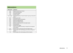 7
7 8
8 9
9 10
10 11
11 12
12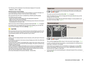 13
13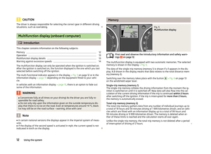 14
14 15
15 16
16 17
17 18
18 19
19 20
20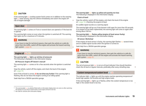 21
21 22
22 23
23 24
24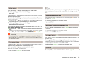 25
25 26
26 27
27 28
28 29
29 30
30 31
31 32
32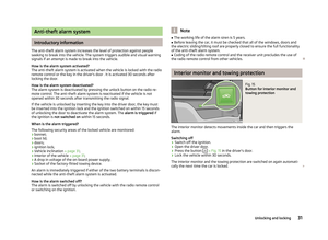 33
33 34
34 35
35 36
36 37
37 38
38 39
39 40
40 41
41 42
42 43
43 44
44 45
45 46
46 47
47 48
48 49
49 50
50 51
51 52
52 53
53 54
54 55
55 56
56 57
57 58
58 59
59 60
60 61
61 62
62 63
63 64
64 65
65 66
66 67
67 68
68 69
69 70
70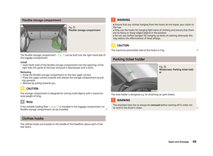 71
71 72
72 73
73 74
74 75
75 76
76 77
77 78
78 79
79 80
80 81
81 82
82 83
83 84
84 85
85 86
86 87
87 88
88 89
89 90
90 91
91 92
92 93
93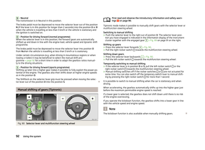 94
94 95
95 96
96 97
97 98
98 99
99 100
100 101
101 102
102 103
103 104
104 105
105 106
106 107
107 108
108 109
109 110
110 111
111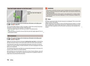 112
112 113
113 114
114 115
115 116
116 117
117 118
118 119
119 120
120 121
121 122
122 123
123 124
124 125
125 126
126 127
127 128
128 129
129 130
130 131
131 132
132 133
133 134
134 135
135 136
136 137
137 138
138 139
139 140
140 141
141 142
142 143
143 144
144 145
145 146
146 147
147 148
148 149
149 150
150 151
151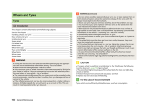 152
152 153
153 154
154 155
155 156
156 157
157 158
158 159
159 160
160 161
161 162
162 163
163 164
164 165
165 166
166 167
167 168
168 169
169 170
170 171
171 172
172 173
173 174
174 175
175 176
176 177
177 178
178 179
179 180
180 181
181 182
182 183
183 184
184 185
185 186
186 187
187 188
188 189
189 190
190 191
191 192
192 193
193 194
194 195
195