Page 9 of 196

Using the system
Cockpit
Overview
Electrical power windows 34
Electric exterior mirror adjustment 48
Air outlet vents 71
Lever for the multifunction switch:
› Turn signal light, headlight and parking light, headlight flasher 42
› Speed regulating system 86
Steering wheel:
› With horn
› With driver’s front airbag 112
› With pushbuttons for radio, navigation system and mobile
phone 95
Instrument cluster: Instruments and warning lights 8
Lever for the multifunction switch:
› Multifunction display 12
› Windscreen wiper and wash system 45
Switch for rear window heater 44
TCS switch 84
Air outlet vents 71
Switch for hazard warning lights 42
Warning light for the deactivated front seat passenger airbag 115
Depending on equipment fitted:
› Operating controls for the heating 71
› Operating controls for the air conditioning system 73
› Operating controls for Climatronic 76
Storage compartments on the front passenger side 66
Front passenger airbag 112
Key-operated switch for the front seat passenger airbag 115
Switch depending on equipment fitted:
› Boot lid remote release 33
› Interior monitor 311
2
3
4
5
6
7
8
9
10
11
12
13
14
15
16
17 Fuse box in the dashboard 169
Light switch and headlamp beam adjustment 38, 41
Bonnet release lever 140
Lever for adjusting the steering wheel 80
Ignition lock 81
Depending on equipment fitted:
› Radio
› Navigation system
Rocker switch for front left seat heating 50
Central locking system 29
Depending on equipment fitted:
› Gearshift lever (manual gearbox) 85
› Selector lever (automatic gearbox) 91
Rocker switch for front right seat heating 50
Depending on equipment fitted:
› Ashtrays 64
› Storage compartment 67
MDI 102
Note
The arrangement of the controls and switches and the location of some items on
right-hand drive models may differ from that shown in »
Fig. 1. The symbols on
the controls and switches are the same as for left-hand drive models. Ð 18
19
20
21
22
23
24
25
26
27
28
29
7
Cockpit
Page 10 of 196

Instruments and Indicator Lights
Instrument cluster
ä
Introduction
This chapter contains information on the following subjects:
Overview 8
Engine revolutions counter 9
Speedometer 9
Coolant temperature gauge 9
Fuel gauge 9
Counter for distance driven 10
Service Interval Display 10
Digital clock 11
Recommended gear 11
WARNING
■ Concentrate fully at all times on your driving! As the driver you are fully re-
sponsible for road safety.
■ Never operate the controls in the instrument cluster while driving, only
when the vehicle is stationary! Ð Overview
Fig. 2
Instrument cluster
First read and observe the introductory information and safety warn-
ings on page 8.
Engine revolutions counter
» page 9
Display:
› With counter for distance driven
» page 10
› With service interval display
» page 10
› With digital clock
» page 11
› With multifunction display
» page 12
› With information display » page 15
Speedometer » page 9
Coolant temperature gauge » page 9
Button for display mode:
› Setting the hours/minutes
› Activating/deactivating the second speed in mph or
km/h
› Service interval - Display of the number of days, kilometres or miles re-
maining until the next Inspection Service 1)
Button for: › Reset trip counter for the distance driven
› Resetting Service Interval Display
£
ä 1
2
3
4
5
6
1)
Valid for countries where the values are indicated in British measuring units.
8 Using the system
Page 11 of 196

›
Set hours/minutes
› Activate/deactivate display mode
Fuel gauge »
page 9 ÐEngine revolutions counter
First read and observe the introductory information and safety warn-
ings on page 8.
The red scale of the rev counter 1
» Fig. 2 on page 8 indicates the range in which
the engine control unit begins to limit the engine speed. The engine control unit
restricts the engine speed to a steady limit.
You should shift into the next higher gear before the red scale of the revolution
counter is reached, or move the selector lever into position D if your car is fitted
with an automatic gearbox.
To maintain the optimum motor speed, observe the gearshift indica-
tor » page 11. For the sake of the environment
Shifting to a higher gear in good time helps to lower fuel consumption, minimises
operating noise levels, protects the environment and contributes to a longer life
and reliability of the engine. ÐSpeedometer
First read and observe the introductory information and safety warn-
ings on page 8.
Warning against excessive speeds
An audible warning signal will sound when the vehicle speed exceeds 120
km/h.
The audible warning signal is switched off when the vehicle speed falls below
this speed limit. Note
This function is only valid for some countries. Ð7
ä
ä Coolant temperature gauge
First read and observe the introductory information and safety warn-
ings on page 8.
The coolant temperature gauge 4
» Fig. 2 on page 8 operates only when the ig-
nition is switched on.
The following guidelines regarding the temperature ranges must be observed to
avoid any damage to the engine.
Cold range
If the pointer is still in the left area of the scale it means that the engine has not
yet reached its operating temperature. Avoid high speeds, full throttle and high
engine loads.
The operating range
The engine has reached its operating temperature as soon as the pointer moves
into the mid-range of the scale, for a normal style of driving. The pointer may also
move further to the right at high engine loads and high outside temperatures. CAUTION
Additional headlights and other attached components in front of the fresh air in-
let impair the cooling efficiency of the coolant. There is then a risk of the engine
overheating at high outside temperatures and high engine loads »
page 19. Ð Fuel gauge
First read and observe the introductory information and safety warn-
ings on page 8.
The fuel gauge 7
» Fig. 2 on page 8 only operates when the ignition is switched
on.
The fuel tank has a capacity of about 45 litres. The indicator light in the instru-
ment cluster lights up when the pointer reaches the reserve mark-
ing » page 22 . CAUTION
Never drive until the fuel tank is completely empty! An irregular supply of fuel can
lead to irregular engine running. Unburnt fuel may get into the exhaust system
and damage the catalytic converter. £
ä
ä
9
Instruments and Indicator Lights
Page 12 of 196

Note
On some vehicles, the fuel gauge is shown in the display of the instrument clus-
ter. ÐCounter for distance driven
First read and observe the introductory information and safety warn-
ings on page 8.
The distance which you have driven with your vehicle is shown in kilometres (km).
In some countries the measuring unit
“mile” is used.
Daily trip counter (trip)
The daily trip counter indicates the distance which you have driven since it was
last reset - in steps of 100 metres or 1/10 of a mile.
To reset the display of the daily trip counter, press button 6
» Fig. 2 on page 8
for longer.
Odometer
The odometer indicates the total distance in kilometres or miles which the vehicle
has been driven.
Fault display
If there is a fault in the instrument cluster Error will appear continuously in the
display. Ensure the fault is rectified as soon as possible by
ŠKODA a specialist ga-
rage. Note
For vehicles fitted with the information display, if the display of the second speed
is activated in mph or km/h, this driving speed is indicated instead of the counter
for the total distance driven. Ð
ä Service Interval Display
Fig. 3
Service Interval Display: Note
First read and observe the introductory information and safety warn-
ings on page 8.
The display can vary depending on the equipment.
Service Interval Display
Before the next service interval a key symbol
and the remaining kilometres are
indicated for 10 seconds after switching on the ignition » Fig. 3. At the same time,
the remaining days until the next service interval are displayed.
The following is displayed in the information display: Service in ...
km or ... days.
The kilometre indicator or the days indicator reduces in steps of 100 km or, where
applicable, days until the service due date is reached.
As soon as the due date for the service is reached, a flashing key symbol and
the text Service appears in the display for 20 seconds after the ignition has been
switched on.
The following is displayed in the information display:
Service now!
Displaying the distance and days until the next service interval
You can use the button 5
to display the remaining distance and days until the
next service interval » Fig. 2 on page 8
.
A key symbol and the remaining distance appear for 10 seconds in the display.
At the same time, the remaining days until the next service interval are displayed.
On vehicles which are equipped with the information display, you can call up this
display in the menu Settings » page 15. £
ä
10 Using the system
Page 13 of 196

The following will be displayed in the information display for 10
seconds:
Service in ... km or ... days.
Resetting Service Interval Display
It is only possible to reset the Service Interval Display, if a service message or at
least a pre-warning is shown in the instrument cluster display.
We recommend that this reset is completed by a ŠKODA specialist garage.
The ŠKODA specialist garage:
› Resets the memory of the display after the appropriate inspection
› Adds an entry to the Service Schedule
› Affixes the sticker with the entry of the following service interval to the side of
the dashboard on the driver's side
Reset the service interval display by using the reset button 6
»
Fig. 2 on page 8.
On vehicles which are equipped with the information display, you can reset the
Service Interval Display in the menu Settings » page 15.CAUTION
We recommend that you do not reset the Service Interval Display yourself as this
can result in the incorrect setting of the Service Interval Display, which can also
cause possible problems with the operation of your vehicle. Note
■ Never reset the display between service intervals, as this will result in the incor-
rect display. ■ Information is retained in the Service Interval Display even after the vehicle bat-
tery is disconnected.
■ If the instrument cluster is exchanged after a repair, the correct values must be
entered in the counter for the Service Interval Display. This work is carried out by
a ŠKODA specialist garage. ■ After resetting the display with flexible service intervals, the displayed data is
the same as that for a vehicle with fixed service intervals. We therefore recom-
mend that the Service Interval Display is only reset by a
ŠKODA Service Partner,
who will reset the display with a vehicle system tester. ■ For more information on the service intervals » Service Plan. Ð Digital clock
First read and observe the introductory information and safety warn-
ings on page 8.
The clock is set with the buttons 5
and 6
» Fig. 2 on page 8.
Select the display that you wish to change with the button 5
and carry out the
change with the button 6
.
On vehicles that are fitted with the information display, it is also possible to set
the clock in the menu Time » page 15. Ð Recommended gear
Fig. 4
Recommended gear
First read and observe the introductory information and safety warn-
ings on page 8.
The currently engaged gear A
is shown in the instrument cluster display
» Fig. 4.
In order to minimise the fuel consumption, a recommendation for shifting into an-
other gear is indicated in the display.
If the control unit recognises that it is beneficial to change gear, an arrow B
is
shown in the display. The arrow points up or down, depending on whether you
should shift into a higher or lower gear.
At the same time, the recommended gear is indicated instead of the currently en-
gaged gear A
.
£
ä
ä
11
Instruments and Indicator Lights
Page 14 of 196

ä
Introduction
This chapter con")
CAUTION
The driver is always responsible for selecting the correct gear in different driving
situations, such as overtaking. ÐMultifunction display (onboard computer)
ä
Introduction
This chapter contains information on the following subjects:
Memory 12
Operation 13
Multifunction display details 13
Warning against excessive speeds 14
The multifunction display can only be operated when the ignition is switched on.
After the ignition is switched on, the function displayed is the one which you last
selected before switching off the ignition.
The multi-functional indicator appears in the display » Fig. 5
on page 12 or in the
information display » page 15 depending on the equipment fitted to your vehi-
cle.
In vehicles with an information display » page 15, there is an option to fade out
some of the information. WARNING
■ Concentrate fully at all times on your driving! As the driver you are fully re-
sponsible for road safety. ■ Do not only rely upon the information given on the outside temperature dis-
play that there is no ice on the road. Even at temperatures around +4 °C, black
ice may still be on the road surface – warning, drive with care! Note
■ In certain national versions the displays appear in the Imperial system of meas-
ures. ■ If the display of the second speed is activated in mph, the current speed is not
indicated in km/h on the display. Ð Memory
Fig. 5
Multifunction display
First read and observe the introductory information and safety warn-
ings on page 12.
The multifunction display is equipped with two automatic memories. The selected
memory is shown in the Display » Fig. 5.
The data of the single-trip memory (memory 1) is shown if a 1 appears in the dis-
play. A 2 shown in the display means that data relates to the total distance mem-
ory (memory
2).
Switching over the memory takes place with the button B
» Fig. 6
on page 13
on the windshield wiper lever.
Single-trip memory (memory 1)
The single-trip memory collates the driving information from the moment the ig-
nition is switched on until it is switched off. New data will also flow into the cal-
culation of the current driving information if the trip is continued within 2 hours
after switching off the ignition. If the trip is interrupted for more than 2 hours,
the memory is automatically erased.
Total-trip memory (memory 2)
The total-trip memory gathers data from any number of individual journeys up to
a total of 19
hours and 59 minutes driving or 1 999 kilometres driven, and on vehi-
cles which are fitted with an information display up to a total of 99 hours and
59 minutes driving or 9 999 kilometres driven. The memory is deleted when ei-
ther of these limits is reached and the calculation starts all over again.
Unlike the single-trip memory, the total-trip memory is not deleted after a period
of interruption of driving of 2 hours. £
ä
12 Using the system
Page 15 of 196

Note
All information in the memory 1 and 2 is erased if the battery of the vehicle is dis-
connected. ÐOperation
Fig. 6
Multifunction display: Control el-
ements
First read and observe the introductory information and safety warn-
ings on page 12.
The rocker switch A
» Fig. 6
and the button B
are located on the windscreen
wiper lever.
Select memory
› Press the button B
» Fig. 6.
Selecting functions
› Briefly press the rocker switch A
» Fig. 6
up or down. This opens the individual
functions of the multifunction display one after the other.
Reseting
› Select the desired memory.
› Press the button B
» Fig. 6 for longer.
The following readouts of the selected memory will be set to zero by button B
:
› Average fuel consumption
› Distance driven
ä ›
Average speed
› Driving time Ð Multifunction display details
First read and observe the introductory information and safety warn-
ings on page 12.
Outside temperature
The current outside temperature is shown in the display.
If the outside temperature drops below +4
°C, a snow flake symbol (warning sig-
nal for ice on the road) appears before the temperature indicator and an audible
signal will sound. After pressing the rocker switch A
» Fig. 6 on page 13, the
function which was shown last is indicated.
Driving time
The driving time which has elapsed since the memory was last erased, appears in
the display. If you want to measure the driving time from a particular moment in
time on, at this moment, reset the memory by setting the button B
» Fig. 6 on
page 13 to zero.
The maximum time indicated in both memories is 19 hours and 59
minutes and on
vehicles which are fitted with an information display, it is 99 hours and 59 mi-
nutes. The indicator is set back to zero if this period is exceeded.
Current fuel consumption
The current fuel consumption level is shown in the display in litres/100 km1)
. You
can use this information to adapt your driving style to the desired fuel consump-
tion.
The display appears in litres/hour if the vehicle is stationary or driving at a low
speed 2)
.
Average fuel consumption
The average fuel consumption since the memory was last erased is shown in the
display in litres/100 km 1)
» page 12. £
ä
1)
On some models in certain countries, the display appears in kilometres/litre.
2) On some models in certain countries, the display appears in --,- kilometres/litres if the vehicle is sta-
tionary.
13
Instruments and Indicator Lights
Page 16 of 196

If you wish to determine the average fuel consumption over a certain period of
time, you must set the memory at the start of the new measurement to zero us-
ing the button
B
» Fig. 6 on page 13 . After erasing the memory, no value appears
in the display until you have driven approx. 300 m.
The display is updated regularly while you are driving.
Range
The estimated range in kilometres is shown on the display. It indicates the dis-
tance you can still drive with your vehicle based on the level of fuel in the tank
and the same style of driving.
The display is shown in steps of 10 km. Once the fuel gauge pointer reaches the
reserve marking, the range is displayed in 5 km.
The fuel consumption over the last 50 km is used to calculate the range. The
range will increase if you drive in a more economical manner.
If the memory is set to zero (after disconnecting the battery), the fuel consump-
tion of 10 ltr./100 km is calculated for the range; afterwards the value is adapted
accordingly to the style of driving.
Distance travelled
The distance travelled since the memory was last erased is shown in the dis-
play » page 12. If you want to measure the distance travelled from a particular
moment in time on, at this moment, reset the memory by setting the button B
» Fig. 6 on page 13 to zero.
The maximum distance indicated in both memories is 1
999 km or 9 999 km on
vehicles with an information display. The indicator is set back to zero if this period
is exceeded.
Average speed
The average speed since the memory was last erased is shown in the display
in km/hour » page 12. To determine the average speed over a certain period of
time, set the memory to zero at the start of the measurement using button B
» Fig. 6 on page 13.
After erasing the memory, no value appears in the display until you have driven
approx. 300 m.
The display is updated regularly while you are driving.
Current speed
The current speed which is identical to the display of the speedometer 3
»
Fig. 2
on page 8 is indicated on the display. Oil temperature
If the oil temperature is lower than 50
°C or if a fault in the system for checking
the oil temperature is present, only - -.- is displayed instead of the oil tempera-
ture. Ð Warning against excessive speeds
First read and observe the introductory information and safety warn-
ings on page 12.
Adjust the speed limit while the vehicle is stationary
›
With button A
» Fig. 6 on page 13, choose the menu point
Warning against ex-
cessive speeds .
› Press the button B
to activate the ability to set the speed limit (value flashes).
› Use the button A
to set the required speed limit, e.g. 50 km/h.
› Confirm the speed limit that was set with button B
, or wait approx. 5 seconds
until the setting is saved automatically (the value stops flashing).
This allows you to set the speed in 5
km/h intervals.
Adjusting the speed limit while the vehicle is moving
› With button A
» Fig. 6 on page 13, choose the menu point
Warning against ex-
cessive speeds .
› Drive at the desired speed, e.g. 50 km/h.
› Press button B
to accept the current speed as the speed limit (the value flash-
es).
If you wish to change the set speed limit, it is changed in 5
km/h intervals (e.g. the
accepted speed of 47 km/h increases to 50 km/h or decreases to 45 km/h).
› Confirm the speed limit that was set by pressing button B
again, or wait ap-
prox. 5 seconds until the setting is saved automatically (the value stops flash-
ing).
Change or delete speed limit
› With button A
» Fig. 6 on page 13, choose the menu point
Warning against ex-
cessive speeds .
› Pressing the button B
deletes the speed limit.
› Pressing the button B
activates the ability to change the speed limit.
If the set speed limit is exceeded, an audible signal will sound as a warning. At
the same time the message Warning against excessive speeds appears on the
display with the set limit value.
The set speed limit value remains stored even after switching off the ignition. Ð
ä
14 Using the system
 1
1 2
2 3
3 4
4 5
5 6
6 7
7 8
8 9
9 10
10 11
11 12
12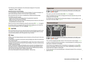 13
13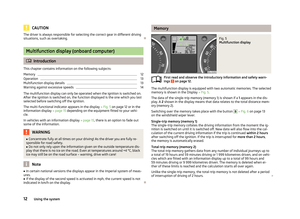 14
14 15
15 16
16 17
17 18
18 19
19 20
20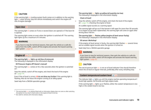 21
21 22
22 23
23 24
24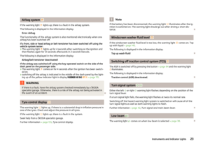 25
25 26
26 27
27 28
28 29
29 30
30 31
31 32
32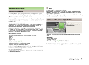 33
33 34
34 35
35 36
36 37
37 38
38 39
39 40
40 41
41 42
42 43
43 44
44 45
45 46
46 47
47 48
48 49
49 50
50 51
51 52
52 53
53 54
54 55
55 56
56 57
57 58
58 59
59 60
60 61
61 62
62 63
63 64
64 65
65 66
66 67
67 68
68 69
69 70
70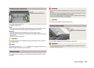 71
71 72
72 73
73 74
74 75
75 76
76 77
77 78
78 79
79 80
80 81
81 82
82 83
83 84
84 85
85 86
86 87
87 88
88 89
89 90
90 91
91 92
92 93
93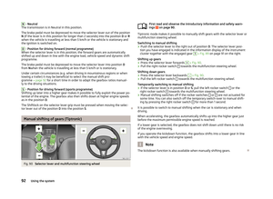 94
94 95
95 96
96 97
97 98
98 99
99 100
100 101
101 102
102 103
103 104
104 105
105 106
106 107
107 108
108 109
109 110
110 111
111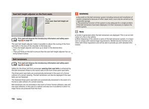 112
112 113
113 114
114 115
115 116
116 117
117 118
118 119
119 120
120 121
121 122
122 123
123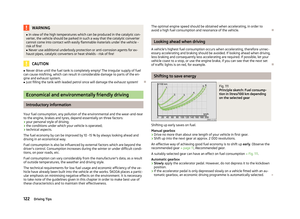 124
124 125
125 126
126 127
127 128
128 129
129 130
130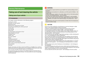 131
131 132
132 133
133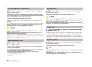 134
134 135
135 136
136 137
137 138
138 139
139 140
140 141
141 142
142 143
143 144
144 145
145 146
146 147
147 148
148 149
149 150
150 151
151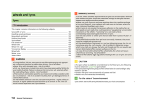 152
152 153
153 154
154 155
155 156
156 157
157 158
158 159
159 160
160 161
161 162
162 163
163 164
164 165
165 166
166 167
167 168
168 169
169 170
170 171
171 172
172 173
173 174
174 175
175 176
176 177
177 178
178 179
179 180
180 181
181 182
182 183
183 184
184 185
185 186
186 187
187 188
188 189
189 190
190 191
191 192
192 193
193 194
194 195
195