2012 MERCEDES-BENZ SL ROADSTER boot
[x] Cancel search: bootPage 580 of 637
Fire extinguisher
G
WARNING
When you brake heavily or change direction
suddenly, the fire extinguisher can be thrown around the vehicle interior if the roller box is
left open. There is a risk of accident and injury
to you or the passenger. Keep the shutter of
the roller box closed whilst the vehicle is in
motion. :
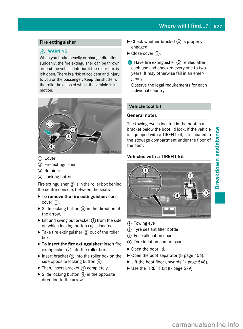
Cover
; Fire extinguisher
= Retainer
? Locking button
Fire extinguisher ;is in the roller box behind
the centre console, between the seats.
X To remove the fire extinguisher: open
cover :.
X Slide locking button ?in the direction of
the arrow.
X Lift and swing out bracket =from the side
on which locking button ?is located.
X Take fire extinguisher ;out of the roller
box.
X To insert the fire extinguisher: insert fire
extinguisher ;into the roller box.
X Insert bracket =into the roller box on the
side opposite locking button ?.
X Then, insert bracket =completely.
X Slide locking button ?in the opposite
direction to the arrow. X
Check whether bracket =is properly
engaged.
X Close cover :.
i Have fire extinguisher
;refilled after
each use and checked every one to two
years. It may otherwise fail in an emer-
gency.
Observe the legal requirements for each
individual country. Vehicle tool kit
General notes The towing eye is located in the boot in a
bracket below the boot lid lock. If the vehicle
is equipped with a TIREFIT kit, it is located in
the stowage compartment under the floor of
the boot.
Vehicles with a TIREFIT kit :
Towing eye
; Tyre sealant filler bottle
= Fuse allocation chart
? Tyre inflation compressor
X Open the boot lid.
X Open the boot separator (Y page 106).
X Lift the boot floor upwards (Y page 548).
X Use the TIREFIT kit (Y page 579). Where will I find...?
577Breakdown assistance Z
Page 581 of 637
Tyre-change tool kit
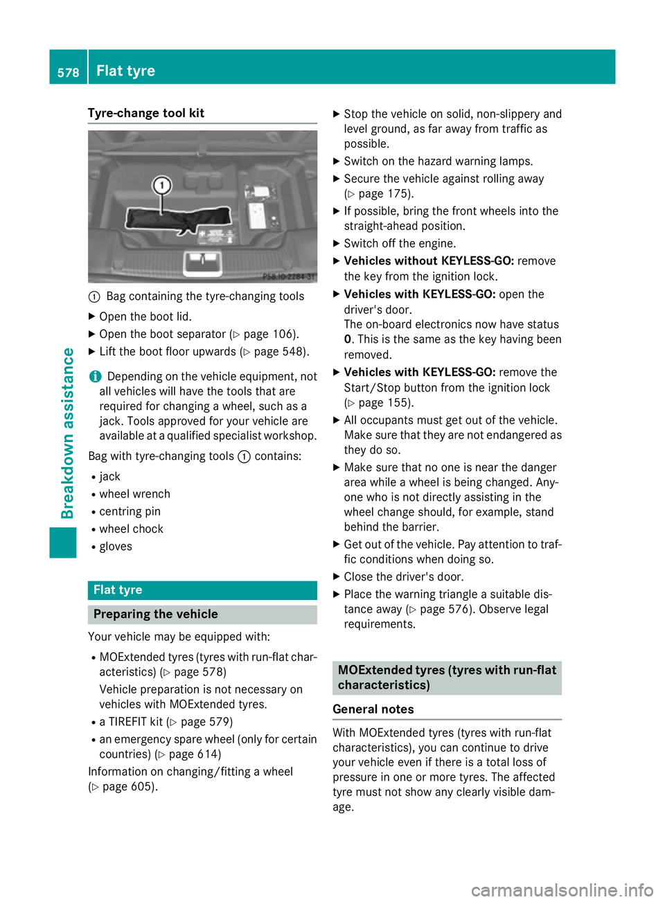
:
Bag containing the tyre-changing tools
X Open the boot lid.
X Open the boot separator (Y page 106).
X Lift the boot floor upwards (Y page 548).
i Depending on the vehicle equipment, not
all vehicles will have the tools that are
required for changing a wheel, such as a
jack. Tools approved for your vehicle are
available at a qualified specialist workshop.
Bag with tyre-changing tools :contains:
R jack
R wheel wrench
R centring pin
R wheel chock
R gloves Flat tyre
Preparing the vehicle
Your vehicle may be equipped with: R MOExtended tyres (tyres with run-flat char-
acteristics) (Y page 578)
Vehicle preparation is not necessary on
vehicles with MOExtended tyres.
R a TIREFIT kit (Y page 579)
R an emergency spare wheel (only for certain
countries) (Y page 614)
Information on changing/fitting a wheel
(Y page 605). X
Stop the vehicle on solid, non-slippery and
level ground, as far away from traffic as
possible.
X Switch on the hazard warning lamps.
X Secure the vehicle against rolling away
(Y page 175).
X If possible, bring the front wheels into the
straight-ahead position.
X Switch off the engine.
X Vehicles without KEYLESS-GO: remove
the key from the ignition lock.
X Vehicles with KEYLESS-GO: open the
driver's door.
The on-board electronics now have status
0. This is the same as the key having been
removed.
X Vehicles with KEYLESS-GO: remove the
Start/Stop button from the ignition lock
(Y page 155).
X All occupants must get out of the vehicle.
Make sure that they are not endangered as
they do so.
X Make sure that no one is near the danger
area while a wheel is being changed. Any-
one who is not directly assisting in the
wheel change should, for example, stand
behind the barrier.
X Get out of the vehicle. Pay attention to traf-
fic conditions when doing so.
X Close the driver's door.
X Place the warning triangle a suitable dis-
tance away (Y page 576). Observe legal
requirements. MOExtended tyres (tyres with run-flat
characteristics)
General notes With MOExtended tyres (tyres with run-flat
characteristics), you can continue to drive
your vehicle even if there is a total loss of
pressure in one or more tyres. The affected
tyre must not show any clearly visible dam-
age. 578
Flat tyreBreakdown assistance
Page 583 of 637
G
WARNING
In the following situations, the tyre sealant is
unable to provide sufficient breakdown assis- tance, as it is unable to seal the tyre properly:
R there are cuts or punctures in the tyre
larger than those mentioned above.
R the wheel rim is damaged.
R you have driven at very low tyre pressures
or on a flat tyre.
There is a risk of an accident.
Do not drive any further. Contact a qualified
specialist workshop. G
WARNING
The tyre sealant is harmful and causes irrita-
tion. It must not come into contact with your
skin, eyes or clothing or be swallowed. Do not inhale TIREFIT fumes. Keep tyre sealant away
from children. There is a risk of injury.
If you come into contact with the tyre sealant,
observe the following:
R Rinse off the tyre sealant from your skin
immediately with water.
R If the tyre sealant comes into contact with
your eyes, immediately rinse them thor-
oughly with clean water.
R If tyre sealant is swallowed, immediately
rinse your mouth out thoroughly and drink
plenty of water. Do not induce vomiting,
and seek medical attention immediately.
R Immediately change out of clothing which
has come into contact with tyre sealant.
R If an allergic reaction occurs, seek medical
attention immediately.
! Do not operate the tyre inflation com-
pressor for longer than eight minutes at a
time without a break. It may otherwise
overheat.
The tyre inflation compressor can be oper-
ated again once it has cooled down.
Comply with the manufacturer’s safety
instructions on the sticker on the tyre infla-
tion compressor. Using the TIREFIT kit
TIREFIT sticker, 2-part
X Do not remove any foreign objects which
have penetrated the tyre, e.g. screws or
nails.
X Remove the tyre sealant bottle, the accom-
panying TIREFIT sticker and the tyre infla-
tion compressor from the stowage space
under the boot floor (Y page 577).
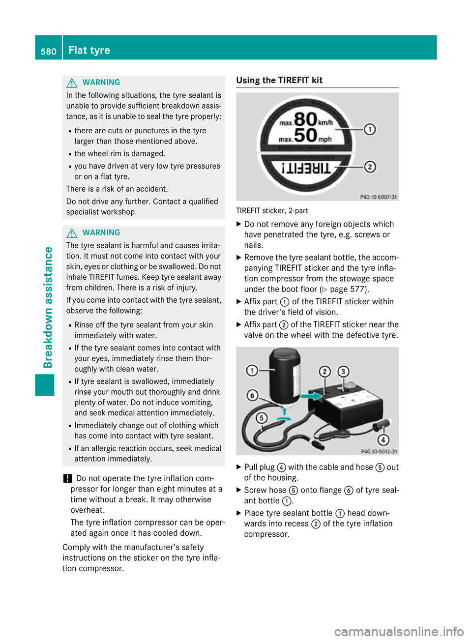
X Affix part :of the TIREFIT sticker within
the driver's field of vision.
X Affix part ;of the TIREFIT sticker near the
valve on the wheel with the defective tyre. X
Pull plug ?with the cable and hose Aout
of the housing.
X Screw hose Aonto flange Bof tyre seal-
ant bottle :.
X Place tyre sealant bottle :head down-
wards into recess ;of the tyre inflation
compressor. 580
Flat tyreBreakdown assistance
Page 595 of 637
i
You can find information on "Jump-start-
ing" under (Y page 586). Electrical fuses
Important safety notes
G
WARNING
If you manipulate, bridge or replace a faulty
fuse with a fuse of a higher amperage, the
electric cables could be overloaded. This may result in a fire. There is a risk of an accident
and injury.
Always replace faulty fuses with specified new fuses of the correct amperage.
! Only use fuses that have been approved
for Mercedes-Benz vehicles and which
have the correct fuse rating for the system concerned. Otherwise, components or sys-
tems could be damaged.
The fuses in your vehicle serve to disconnect
faulty circuits. If a fuse blows, all the compo- nents on the circuit and their functions will
fail.
Blown fuses must be replaced with fuses of
the same rating, which you can recognise by
the colour and fuse rating. The fuse ratings
are listed in the fuse allocation chart.
If the newly inserted fuse also blows, have the
cause traced and rectified at a qualified spe-
cialist workshop, e.g. a Mercedes-Benz Ser-
vice Centre. Before replacing a fuse
X Secure the vehicle against rolling away
(Y page 175).
X Switch off all electrical consumers.
X Turn the key to position 0in the ignition
lock and remove it (Y page 155).
or
X On vehicles with KEYLESS-GO, make sure
the ignition is switched off (Y page 155).All indicator lamps in the instrument cluster
must be off.
The fuses are located in various fuse boxes:
R fuse box in the engine compartment on the
right-hand side of the vehicle, when viewed
in the direction of travel
R dashboard fuse box
R fuse box in the rear compartment on the
right-hand side of the vehicle, when viewed
in the direction of travel
The fuse allocation chart is located in the
vehicle tool kit in the stowage compartment
under the boot floor (Y page 577). Dashboard fuse box
i Observe the "Important safety notes" sec-
tion (Y page 592).
! Do not use a pointed object such as a
screwdriver to open the cover in the dash-
board. You could damage the dashboard or
the cover.
! Make sure that no moisture can enter the
fuse box when the cover is open.
! When closing the cover, make sure that it
is lying correctly on the fuse box. Moisture
seeping in or dirt could otherwise impair
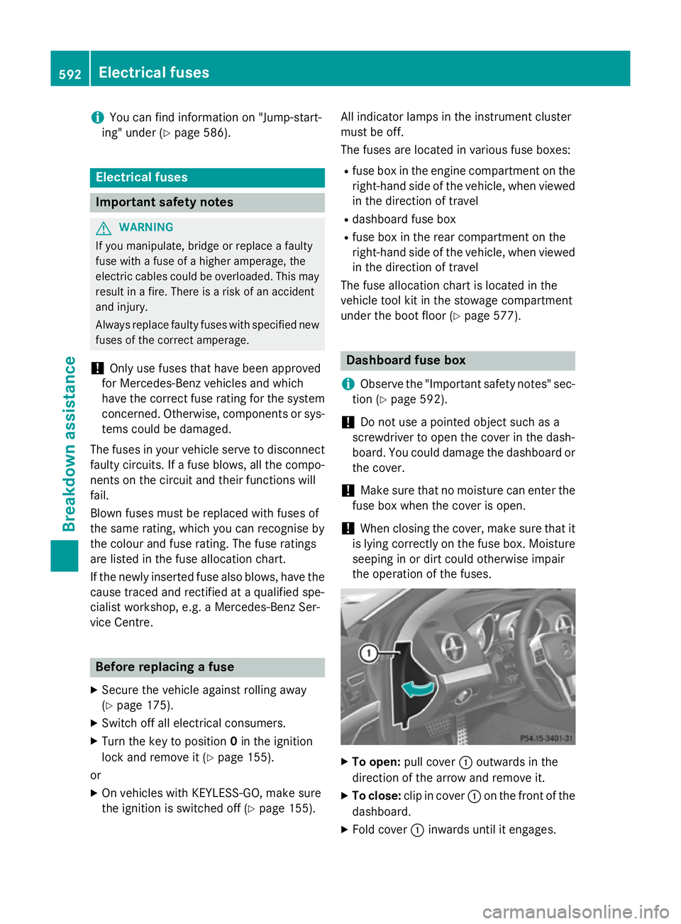
the operation of the fuses. X
To open: pull cover :outwards in the
direction of the arrow and remove it.
X To close: clip in cover :on the front of the
dashboard.
X Fold cover :inwards until it engages. 592
Electrical fusesBreakdown assistance
Page 610 of 637
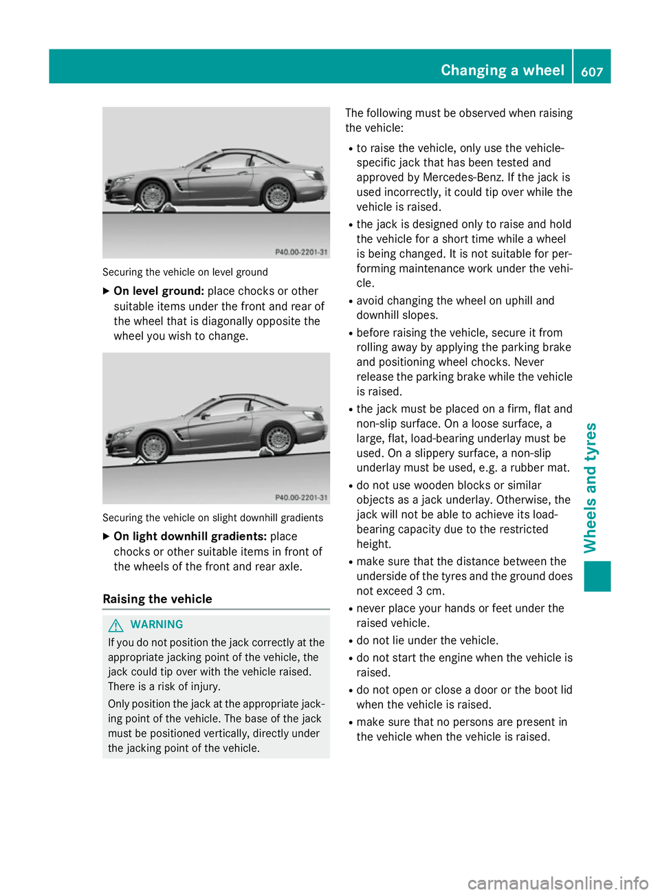
Securing the vehicle on level ground
X On level ground: place chocks or other
suitable items under the front and rear of
the wheel that is diagonally opposite the
wheel you wish to change. Securing the vehicle on slight downhill gradients
X On light downhill gradients: place
chocks or other suitable items in front of
the wheels of the front and rear axle.
Raising the vehicle G
WARNING
If you do not position the jack correctly at the appropriate jacking point of the vehicle, the
jack could tip over with the vehicle raised.
There is a risk of injury.
Only position the jack at the appropriate jack-
ing point of the vehicle. The base of the jack
must be positioned vertically, directly under
the jacking point of the vehicle. The following must be observed when raising
the vehicle:
R to raise the vehicle, only use the vehicle-
specific jack that has been tested and
approved by Mercedes-Benz. If the jack is
used incorrectly, it could tip over while the
vehicle is raised.
R the jack is designed only to raise and hold
the vehicle for a short time while a wheel
is being changed. It is not suitable for per-
forming maintenance work under the vehi- cle.
R avoid changing the wheel on uphill and
downhill slopes.
R before raising the vehicle, secure it from
rolling away by applying the parking brake
and positioning wheel chocks. Never
release the parking brake while the vehicle
is raised.
R the jack must be placed on a firm, flat and
non-slip surface. On a loose surface, a
large, flat, load-bearing underlay must be
used. On a slippery surface, a non-slip
underlay must be used, e.g. a rubber mat.
R do not use wooden blocks or similar
objects as a jack underlay. Otherwise, the
jack will not be able to achieve its load-
bearing capacity due to the restricted
height.
R make sure that the distance between the
underside of the tyres and the ground does
not exceed 3 cm.
R never place your hands or feet under the
raised vehicle.
R do not lie under the vehicle.
R do not start the engine when the vehicle is
raised.
R do not open or close a door or the boot lid
when the vehicle is raised.
R make sure that no persons are present in
the vehicle when the vehicle is raised. Changing a wheel
607Wheels and tyres Z
Page 613 of 637
X
Turn the crank of the jack anti-clockwise
until the vehicle is once again standing
firmly on the ground.
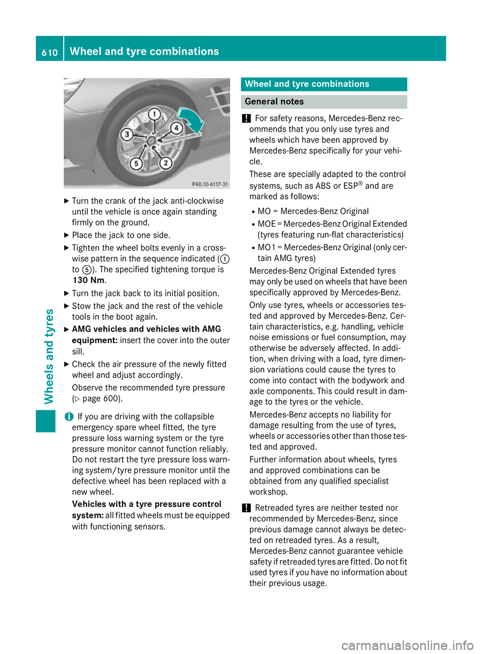
X Place the jack to one side.
X Tighten the wheel bolts evenly in a cross-
wise pattern in the sequence indicated ( :
to A). The specified tightening torque is
130 Nm.
X Turn the jack back to its initial position.
X Stow the jack and the rest of the vehicle
tools in the boot again.
X AMG vehicles and vehicles with AMG
equipment: insert the cover into the outer
sill.
X Check the air pressure of the newly fitted
wheel and adjust accordingly.
Observe the recommended tyre pressure
(Y page 600).
i If you are driving with the collapsible
emergency spare wheel fitted, the tyre
pressure loss warning system or the tyre
pressure monitor cannot function reliably.
Do not restart the tyre pressure loss warn- ing system/tyre pressure monitor until the
defective wheel has been replaced with a
new wheel.
Vehicles with a tyre pressure control
system: all fitted wheels must be equipped
with functioning sensors. Wheel and tyre combinations
General notes
! For safety reasons, Mercedes-Benz rec-
ommends that you only use tyres and
wheels which have been approved by
Mercedes-Benz specifically for your vehi-
cle.
These are specially adapted to the control
systems, such as ABS or ESP ®
and are
marked as follows:
R MO = Mercedes-Benz Original
R MOE = Mercedes-Benz Original Extended
(tyres featuring run-flat characteristics)
R MO1 = Mercedes-Benz Original (only cer-
tain AMG tyres)
Mercedes-Benz Original Extended tyres
may only be used on wheels that have been
specifically approved by Mercedes-Benz.
Only use tyres, wheels or accessories tes-
ted and approved by Mercedes-Benz. Cer-
tain characteristics, e.g. handling, vehicle
noise emissions or fuel consumption, may
otherwise be adversely affected. In addi-
tion, when driving with a load, tyre dimen-
sion variations could cause the tyres to
come into contact with the bodywork and
axle components. This could result in dam- age to the tyres or the vehicle.
Mercedes-Benz accepts no liability for
damage resulting from the use of tyres,
wheels or accessories other than those tes- ted and approved.
Further information about wheels, tyres
and approved combinations can be
obtained from any qualified specialist
workshop.
! Retreaded tyres are neither tested nor
recommended by Mercedes-Benz, since
previous damage cannot always be detec-
ted on retreaded tyres. As a result,
Mercedes-Benz cannot guarantee vehicle
safety if retreaded tyres are fitted. Do not fit
used tyres if you have no information about their previous usage. 610
Wheel and tyre combinationsWheels and tyres
Page 618 of 637
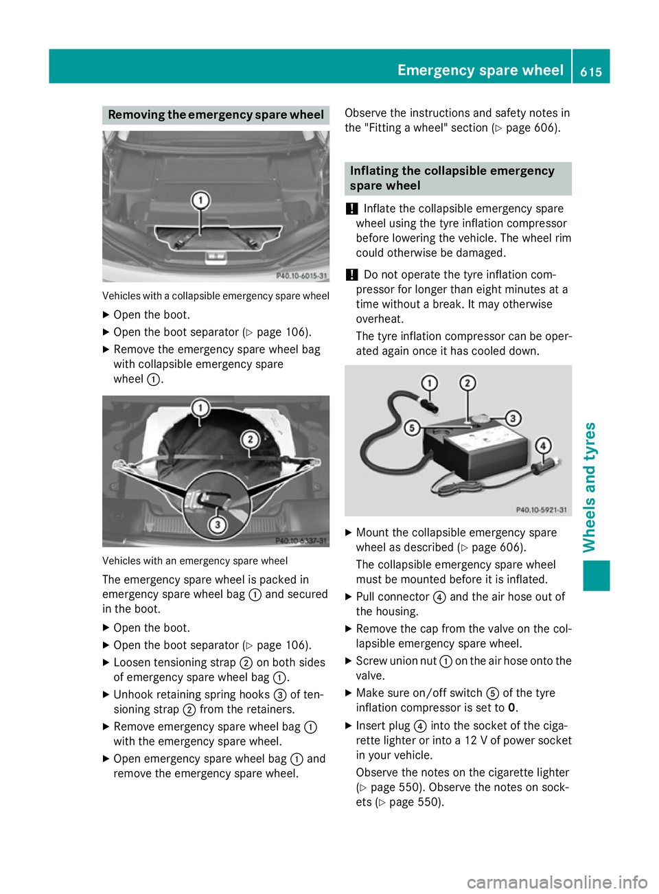
Removing the emergency spare wheel
Vehicles with a collapsible emergency spare wheel
X Open the boot.
X Open the boot separator (Y page 106).
X Remove the emergency spare wheel bag
with collapsible emergency spare
wheel :. Vehicles with an emergency spare wheel
The emergency spare wheel is packed in
emergency spare wheel bag :and secured
in the boot.
X Open the boot.
X Open the boot separator (Y page 106).
X Loosen tensioning strap ;on both sides
of emergency spare wheel bag :.
X Unhook retaining spring hooks =of ten-
sioning strap ;from the retainers.
X Remove emergency spare wheel bag :
with the emergency spare wheel.
X Open emergency spare wheel bag :and
remove the emergency spare wheel. Observe the instructions and safety notes in
the "Fitting a wheel" section (Y
page 606). Inflating the collapsible emergency
spare wheel
! Inflate the collapsible emergency spare
wheel using the tyre inflation compressor
before lowering the vehicle. The wheel rim
could otherwise be damaged.
! Do not operate the tyre inflation com-
pressor for longer than eight minutes at a
time without a break. It may otherwise
overheat.
The tyre inflation compressor can be oper-
ated again once it has cooled down. X
Mount the collapsible emergency spare
wheel as described (Y page 606).
The collapsible emergency spare wheel
must be mounted before it is inflated.
X Pull connector ?and the air hose out of
the housing.
X Remove the cap from the valve on the col-
lapsible emergency spare wheel.
X Screw union nut :on the air hose onto the
valve.
X Make sure on/off switch Aof the tyre
inflation compressor is set to 0.
X Insert plug ?into the socket of the ciga-
rette lighter or into a 12 V of power socket in your vehicle.
Observe the notes on the cigarette lighter
(Y page 550). Observe the notes on sock-
ets (Y page 550). Emergency spare wheel
615Wheels and tyres Z
Page 632 of 637
Vehicle data
General notes
Please note that for the specified vehicle
data:
R the heights specified may vary as a result
of:
- tyres
- load
- condition of the suspension
- optional equipment
R optional equipment reduces the maximum
payload.
R vehicle-specific weight information can be
found on the vehicle identification plate
(Y page 622).
R only for certain countries: you can find vehi-
cle-specific vehicle data in the COC docu-
ments (CERTIFICATE OF CONFORMITY).
These documents are delivered with your
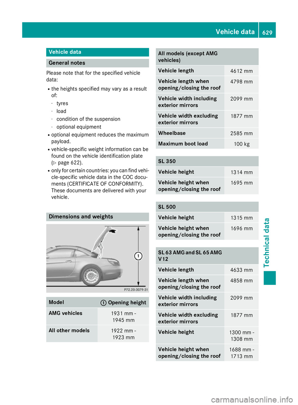
vehicle. Dimensions and weights
Model
: :
Opening height AMG vehicles
1931 mm -
1945 mm All other models
1922 mm -
1923 mm All models (except AMG
vehicles)
Vehicle length
4612 mm
Vehicle length when
opening/closing the roof
4798 mm
Vehicle width including
exterior mirrors
2099 mm
Vehicle width excluding
exterior mirrors
1877 mm
Wheelbase
2585 mm
Maximum boot load
100 kg
SL 350
Vehicle height
1314 mm
Vehicle height when
opening/closing the roof
1695 mm
SL 500
Vehicle height
1315 mm
Vehicle height when
opening/closing the roof
1696 mm
SL 63 AMG and SL 65 AMG
V12 Vehicle length
4633 mm
Vehicle length when
opening/closing the roof
4858 mm
Vehicle width including
exterior mirrors
2099 mm
Vehicle width excluding
exterior mirrors
1877 mm
Vehicle height
1300 mm -
1308 mm Vehicle height when
opening/closing the roof
1688 mm -
1713 mm Vehicle data
629Technical data Z