2012 MERCEDES-BENZ SL ROADSTER reset
[x] Cancel search: resetPage 30 of 637
Text messages
Telephone module with Blue-
tooth® (SAP profile) ...................... 425
Text messages (SMS)
Notes and requirements ................ 409
Theft-deterrent system
ATA (Anti-Theft Alarm system )......... 79
Immobiliser ...................................... 79
Time
Setting ........................................... 312
Setting summer/standard time ..... 311
Setting the format ......................... 311
Setting the time ............................. 311
Setting the time manually .............. 311
Setting the time zone ..................... 311
Setting the time/date format ........ 311
Timing (RACETIMER) ......................... 245
TIREFIT kit .......................................... 579
TMC (Traffic Message Channel)
Displays on the map ...................... 365
Switching dynamic route guid-
ance on/of f................................... 364
Tone settings ..................................... 300
Balance and fader .......................... 300
Total distance recorder .................... 231
Tow-away protection
Activating ......................................... 80
Deactivating ..................................... 80
Function ........................................... 80
Tow-starting
Emergency engine starting ............ 591
Important safety notes .................. 588
Towing
Important safety notes .................. 588
With the rear axle raised ................ 590
Towing away
Fitting the towing eye .................... 589
Removing the towing eye ............... 590
With both axles on the ground ....... 591
Track
Selecting (CD, DVD, MP3 ).............. 475
Selecting using the number key-
pad ................................................ 475
Track information .............................. 530
Traffic Announcement (TA)
Interrupting .................................... 468
Notes ............................................. 467 Switching on/of
f........................... 467
Traffic jam function ........................... 357
Traffic jam icon .................................. 365
Showing on route ........................... 365
Traffic jam message .......................... 367
Reading out on route ..................... 367
Traffic jams ........................................ 365
Showing in the map ....................... 365
Traffic Message Channel
see TMC (Traffic Message Channel)
Traffic messages
see Dynamic route guidance/TMC
Traffic Programme (TA)
Switching off .................................. 299
Traffic reports ........................... 365, 367
Reading out on route ..................... 367
Real-time traffic news .................... 366
Showing in the map ....................... 365
Showing on route ........................... 365
Traffic symbol information ............. 365
Transmission
Selector lever ................................ 163
see Automatic transmission
Transporting the vehicle .................. 591
Travel guide
Activating/deactivating data ......... 348
Calling up ....................................... 349
Choosing topics ............................. 350
Exploring a destination or route ..... 350
Selecting a destination or route on
the map ......................................... 350
ViaMichelin .................................... 348
Trim pieces (cleaning instruc-
tions) .................................................. 573
Trip computer (on-board com-
puter) .................................................. 231
Trip meter
Calling up ....................................... 231
Resetting (on-board computer) ...... 232
True Image™ ...................................... 302
Turn signals
Switching on/of f........................... 129
TV
Alphabetical browser ..................... 506
Automatic picture shutoff .............. 501
Digital teletext (MHEG-5) ............... 508
Fixing a channel ............................. 507 Index
27
Page 37 of 637
G
WARNING
If you connect equipment to a diagnostics
connection in the vehicle, it can affect the
operation of the vehicle systems. This may
affect the operating safety of the vehicle.
There is a risk of an accident.
Do not connect any equipment to a diagnos-
tics connection in the vehicle. G
WARNING
Objects in the driver's footwell may restrict
the clearance around the pedals or block a
depressed pedal. This jeopardises the oper-
ating and road safety of the vehicle. There is a risk of an accident.
Stow all objects securely in the vehicle so that
they do not get into the driver's footwell.
Always fit the floormats securely and as pre-
scribed in order to ensure that there is always sufficient room for the pedals. Do not use
loose floormats and do not place several floor- mats on top of one another.
! If the engine is switched off and equip-
ment on the diagnostics connection is
used, the starter battery may discharge.
Connecting equipment to the diagnostics
connection can lead to emissions monitoring information being reset, for example. This
may lead to the vehicle failing to meet the
requirements of the next emissions test dur-
ing the main inspection. Qualified specialist workshop
A qualified specialist workshop has the nec-
essary special skills, tools and qualifications
to correctly carry out any necessary work on
your vehicle. This particularly applies to work
relevant to safety.
Observe the notes in the Service Booklet.
Always have the following work carried out at a qualified specialist workshop:
R work relevant to safety
R service and maintenance work R
repair work
R modifications, installations and conver-
sions
R work on electronic components
Mercedes-Benz recommends that you use a
Mercedes-Benz Service Centre. Vehicle registration
Mercedes-Benz may ask its Service Centres
to carry out technical inspections on certain
vehicles. The quality or safety of the vehicle is
improved as a result of the inspection.
Mercedes-Benz can only inform you about
vehicle checks if it has your registration data.
It is possible that your vehicle has not yet
been registered in your name in the following
cases:
R if your vehicle was not purchased at an
authorised specialist dealer.
R if your vehicle has not yet been examined at
a Mercedes-Benz Service Centre.
It is advisable to register your vehicle with a
Mercedes-Benz Service Centre.
Inform Mercedes-Benz as soon as possible
about any change in address or vehicle own-
ership. You can do this at a Mercedes-Benz
Service Centre, for example. Correct use
If you remove any warning stickers, you or
others could fail to recognise certain dangers.
Leave warning stickers in position.
Observe the following information when driv- ing your vehicle:
R the safety notes in this manual
R the technical data in this manual
R traffic rules and regulations
R laws and safety standards pertaining to
motor vehicles 34
Introduction
Page 60 of 637
If the seat belts are not released:
X Move the backrest or seat back slightly, but
only when the vehicle is stationary.
Seat belt pre-tensioning is reduced and the locking mechanism is released.
The seat-belt adjustment is an integral part of
the PRE-SAFE ®
convenience function. More
information about seat-belt adjustment can
be found under "Seat-belt adjustment"
(Y page 59). NECK-PRO head restraints
Important safety notes G
WARNING
Only use head restraint covers which have
been tested and approved by Mercedes-Benz
for your vehicle model.
The use of non-approved head restraint cov-
ers may prevent NECK-PRO head restraints
from triggering properly. Consequently, the
NECK-PRO head restraints cannot provide the
intended level of protection.
Consult a Mercedes-Benz Service Centre
regarding availability.
NECK-PRO head restraints reduce the likeli-
hood of head and chest injuries. The NECK-
PRO head restraints on the driver's and front-
passenger seats are moved forwards and
upwards in the event of a rear-end collision of
a certain severity. This provides better head
support.
If the NECK-PRO head restraints have been
triggered in an accident, reset the NECK-PRO head restraints on the driver’s and front-
passenger seat (Y page 57). Otherwise, the
additional protection will not be available in
the event of another rear-end collision. You
can recognise when NECK-PRO head
restraints have been triggered by the fact that they have moved forwards and can no longerbe adjusted.
Mercedes-Benz recommends that you have
the NECK-PRO head restraints checked at a qualified specialist workshop after a rear-end
collision.
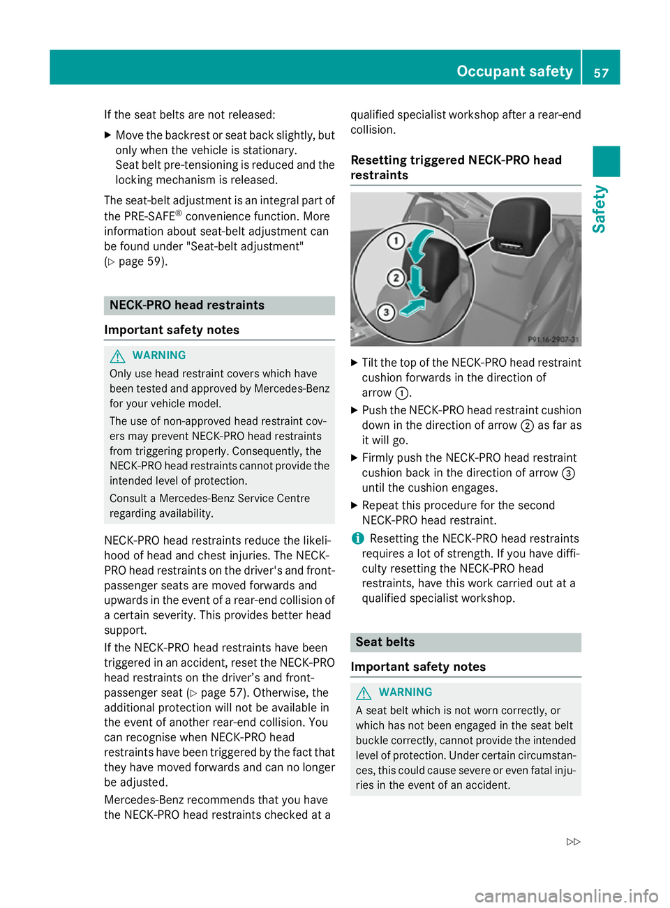
Resetting triggered NECK-PRO head
restraints X
Tilt the top of the NECK-PRO head restraint
cushion forwards in the direction of
arrow :.
X Push the NECK-PRO head restraint cushion
down in the direction of arrow ;as far as
it will go.
X Firmly push the NECK-PRO head restraint
cushion back in the direction of arrow =
until the cushion engages.
X Repeat this procedure for the second
NECK-PRO head restraint.
i Resetting the NECK-PRO head restraints
requires a lot of strength. If you have diffi-
culty resetting the NECK-PRO head
restraints, have this work carried out at a
qualified specialist workshop. Seat belts
Important safety notes G
WARNING
A seat belt which is not worn correctly, or
which has not been engaged in the seat belt
buckle correctly, cannot provide the intended level of protection. Under certain circumstan-
ces, this could cause severe or even fatal inju- ries in the event of an accident. Occupant safety
57Safety
Z
Page 103 of 637
G
WARNING
The reversing function does not react:
R to soft, light and thin objects, e.g. small fin-
gers
R while resetting
This means that the reversing feature cannot
prevent someone being trapped in these sit-
uations. There is a risk of injury.
When closing, make sure that no parts of the
body are in the closing area. If someone
becomes trapped, press the switch to open
the side window again. Opening and closing the side win-
dows
Opening and closing the side windows
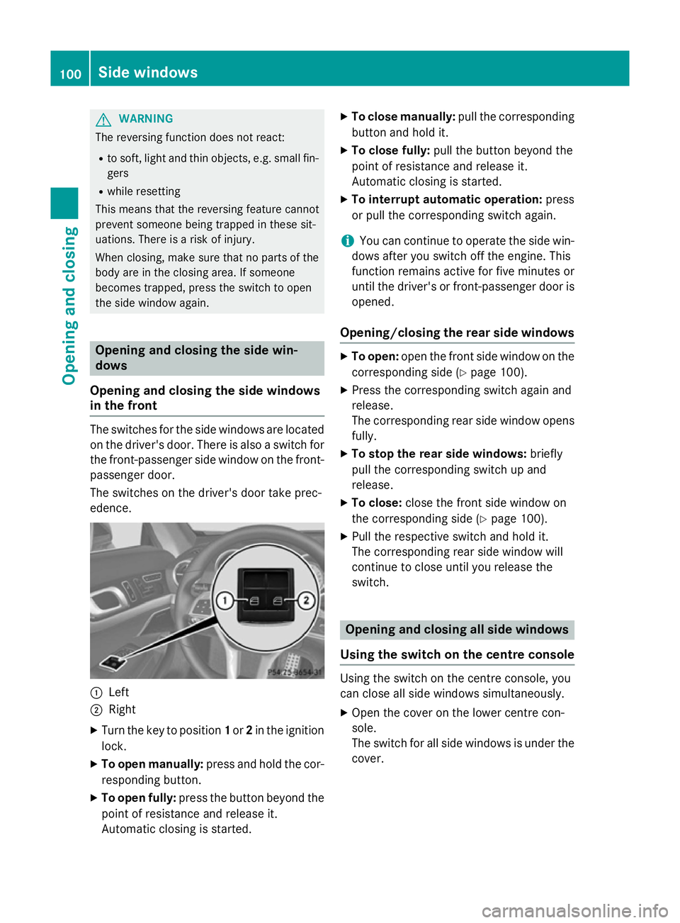
in the front The switches for the side windows are located
on the driver's door. There is also a switch for
the front-passenger side window on the front- passenger door.
The switches on the driver's door take prec-
edence. :
Left
; Right
X Turn the key to position 1or 2in the ignition
lock.
X To open manually: press and hold the cor-
responding button.
X To open fully: press the button beyond the
point of resistance and release it.
Automatic closing is started. X
To close manually: pull the corresponding
button and hold it.
X To close fully: pull the button beyond the
point of resistance and release it.
Automatic closing is started.
X To interrupt automatic operation: press
or pull the corresponding switch again.
i You can continue to operate the side win-
dows after you switch off the engine. This
function remains active for five minutes or
until the driver's or front-passenger door is opened.
Opening/closing the rear side windows X
To open: open the front side window on the
corresponding side (Y page 100).
X Press the corresponding switch again and
release.
The corresponding rear side window opens
fully.
X To stop the rear side windows: briefly
pull the corresponding switch up and
release.
X To close: close the front side window on
the corresponding side (Y page 100).
X Pull the respective switch and hold it.
The corresponding rear side window will
continue to close until you release the
switch. Opening and closing all side windows
Using the switch on the centre console Using the switch on the centre console, you
can close all side windows simultaneously.
X
Open the cover on the lower centre con-
sole.
The switch for all side windows is under the
cover. 100
Side windowsOpening and closing
Page 105 of 637
X
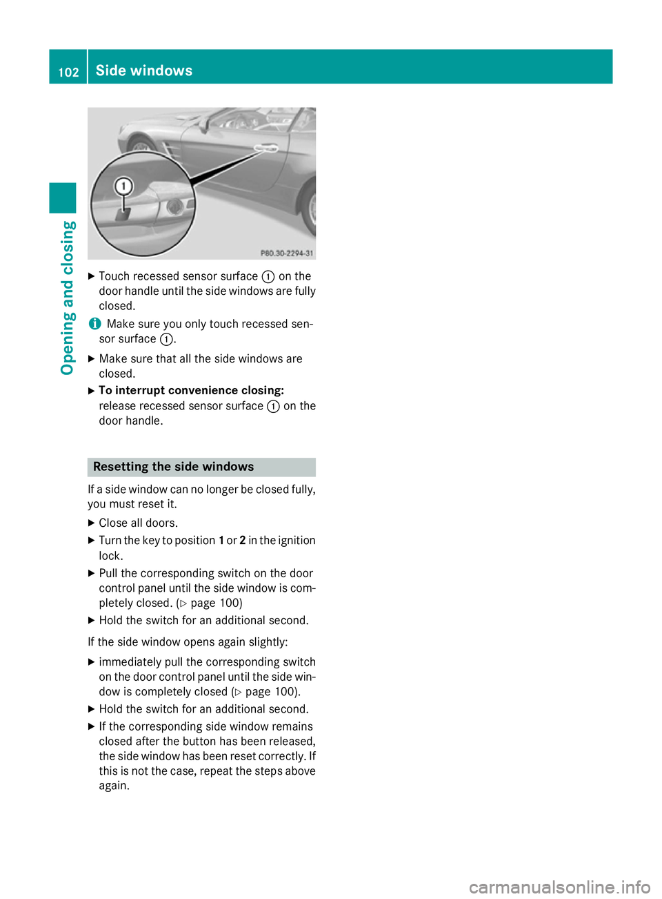
Touch recessed sensor surface :on the
door handle until the side windows are fully
closed.
i Make sure you only touch recessed sen-
sor surface :.
X Make sure that all the side windows are
closed.
X To interrupt convenience closing:
release recessed sensor surface :on the
door handle. Resetting the side windows
If a side window can no longer be closed fully, you must reset it.
X Close all doors.
X Turn the key to position 1or 2in the ignition
lock.
X Pull the corresponding switch on the door
control panel until the side window is com-
pletely closed. (Y page 100)
X Hold the switch for an additional second.
If the side window opens again slightly: X immediately pull the corresponding switch
on the door control panel until the side win-
dow is completely closed (Y page 100).
X Hold the switch for an additional second.
X If the corresponding side window remains
closed after the button has been released,
the side window has been reset correctly. If this is not the case, repeat the steps aboveagain. 102
Side windowsOpening and closing
Page 106 of 637
Problems with the side windows
G
WARNING
If you close a side window again immediately after it has been blocked or reset, the side window
closes with increased or maximum force. The reversing function is then not active. Parts of the
body could be trapped in the closing area in the process. This poses an increased risk of injury or even fatal injury.
Make sure that no parts of the body are in the closing area. To stop the closing process, releasethe switch or push the switch again to reopen the side window. Problem
Possible causes/consequences and
M MSolutions A side window cannot
be closed because it is
blocked by objects, e.g.
leaves in the window
guide. X
Remove the objects.
X Close the side window. A side window cannot
be closed and you can-
not see the cause. If a side window is obstructed during closing and reopens again
slightly:
X Immediately after the window blocks, pull the corresponding
switch again until the side window has closed.
The side window is closed with increased force.
If a side window is obstructed again during closing and reopens
again slightly: X Immediately after the window blocks, pull the corresponding
switch again until the side window has closed.
The side window is closed without the anti-entrapment feature. Roof
Important safety notes
G
WARNING
If you do not fully open/close the soft top, the soft-top hydraulics depressurise after a short time. This causes the soft top to lower unex-
pectedly and may cause you or others to be
trapped. There is a risk of injury.
Always open or close the soft top completely. G
WARNING
Closing the roof manually is a complex, tech-
nically challenging procedure that requires
considerable effort during certain phases. You or others could be trapped while perform-
ing this task. There is a risk of injury.
Only have the soft top closed manually at a
qualified specialist workshop.
! Never sit on the rear compartment trim or
stow heavy objects there. You will other-
wise damage the roof and rear compart-
ment trim of the vehicle.
! Do not forget that the weather can
change abruptly. Make certain that the roof
is closed when you leave the vehicle. The
vehicle electronics can be damaged if
water enters the vehicle interior. Roof
103Opening and closing Z
Page 124 of 637
Folding the exterior mirrors in/out elec-
trically X
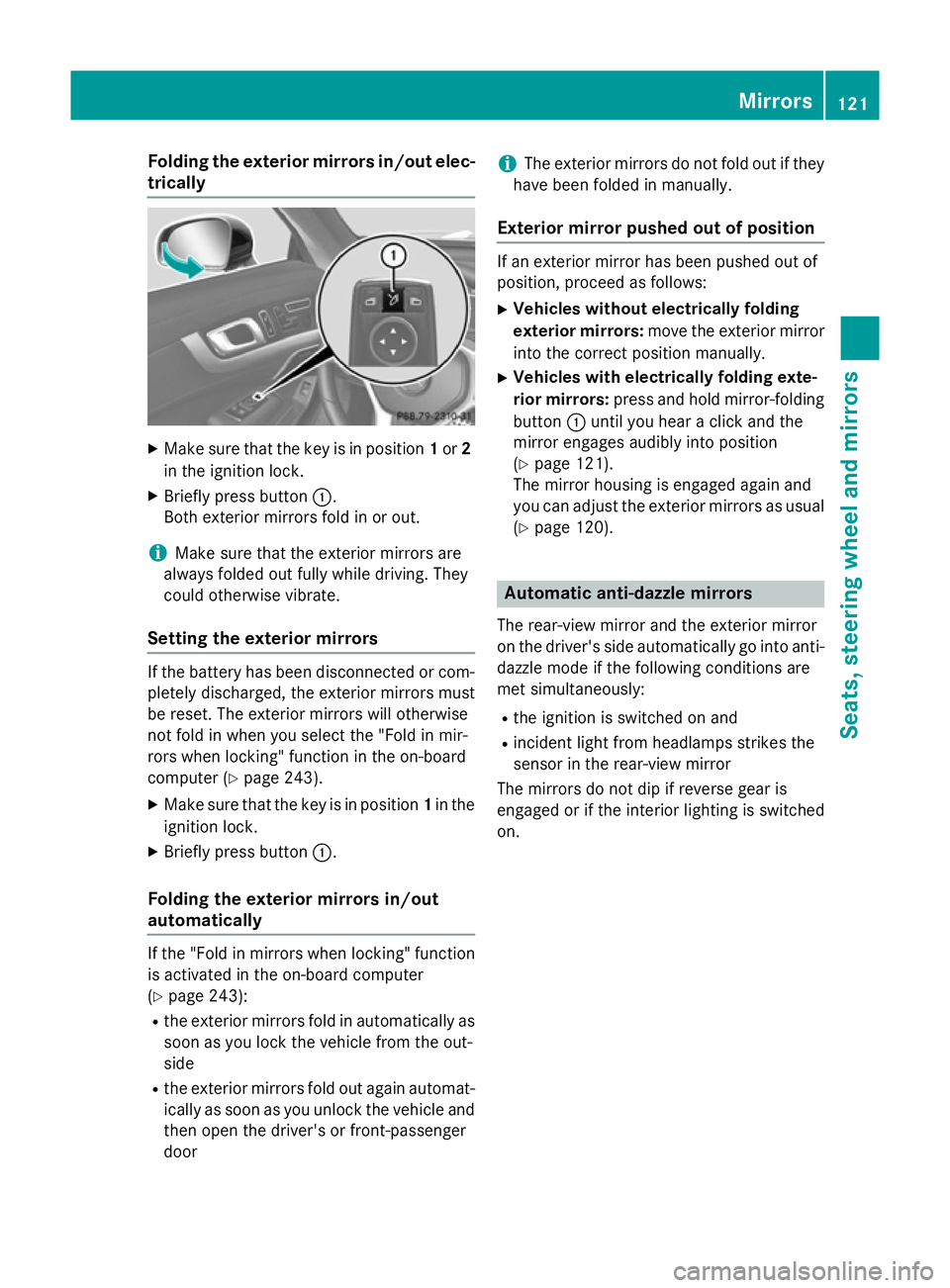
Make sure that the key is in position 1or 2
in the ignition lock.
X Briefly press button :.
Both exterior mirrors fold in or out.
i Make sure that the exterior mirrors are
always folded out fully while driving. They
could otherwise vibrate.
Setting the exterior mirrors If the battery has been disconnected or com-
pletely discharged, the exterior mirrors must
be reset. The exterior mirrors will otherwise
not fold in when you select the "Fold in mir-
rors when locking" function in the on-board
computer (Y page 243).
X Make sure that the key is in position 1in the
ignition lock.
X Briefly press button :.
Folding the exterior mirrors in/out
automatically If the "Fold in mirrors when locking" function
is activated in the on-board computer
(Y page 243):
R the exterior mirrors fold in automatically as
soon as you lock the vehicle from the out-
side
R the exterior mirrors fold out again automat-
ically as soon as you unlock the vehicle and
then open the driver's or front-passenger
door i
The exterior mirrors do not fold out if they
have been folded in manually.
Exterior mirror pushed out of position If an exterior mirror has been pushed out of
position, proceed as follows:
X Vehicles without electrically folding
exterior mirrors: move the exterior mirror
into the correct position manually.
X Vehicles with electrically folding exte-
rior mirrors: press and hold mirror-folding
button :until you hear a click and the
mirror engages audibly into position
(Y page 121).
The mirror housing is engaged again and
you can adjust the exterior mirrors as usual
(Y page 120). Automatic anti-dazzle mirrors
The rear-view mirror and the exterior mirror
on the driver's side automatically go into anti- dazzle mode if the following conditions are
met simultaneously:
R the ignition is switched on and
R incident light from headlamps strikes the
sensor in the rear-view mirror
The mirrors do not dip if reverse gear is
engaged or if the interior lighting is switched
on. Mirrors
121Seats, steering wheel and mirrors Z
Page 125 of 637
Parking position of the exterior mirror
on the front-passenger side
Setting and storing the parking position Using reverse gear
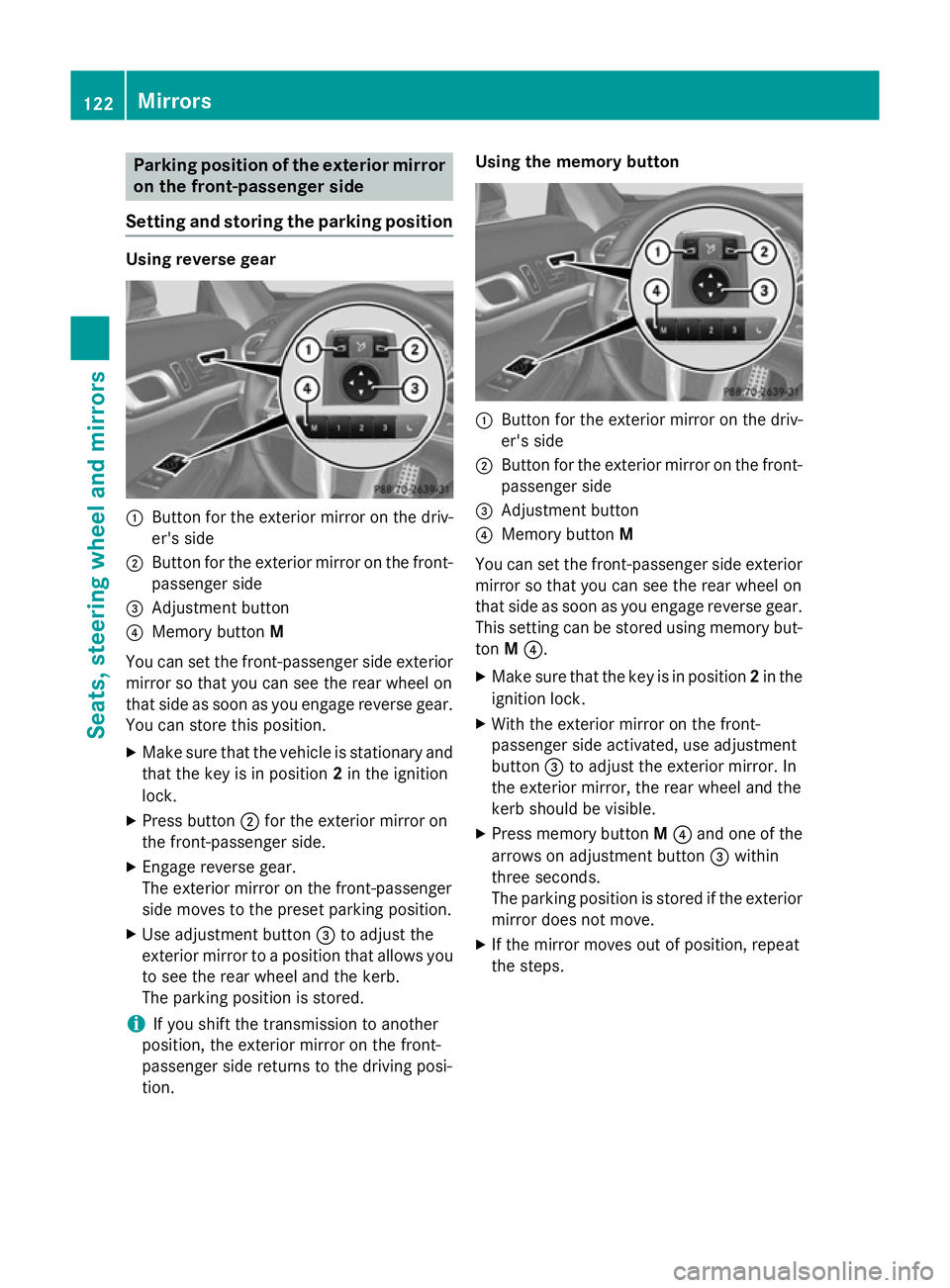
:
Button for the exterior mirror on the driv-
er's side
; Button for the exterior mirror on the front-
passenger side
= Adjustment button
? Memory button M
You can set the front-passenger side exterior
mirror so that you can see the rear wheel on
that side as soon as you engage reverse gear.
You can store this position.
X Make sure that the vehicle is stationary and
that the key is in position 2in the ignition
lock.
X Press button ;for the exterior mirror on
the front-passenger side.
X Engage reverse gear.
The exterior mirror on the front-passenger
side moves to the preset parking position.
X Use adjustment button =to adjust the
exterior mirror to a position that allows you to see the rear wheel and the kerb.
The parking position is stored.
i If you shift the transmission to another
position, the exterior mirror on the front-
passenger side returns to the driving posi-
tion. Using the memory button
:
Button for the exterior mirror on the driv-
er's side
; Button for the exterior mirror on the front-
passenger side
= Adjustment button
? Memory button M
You can set the front-passenger side exterior
mirror so that you can see the rear wheel on
that side as soon as you engage reverse gear.
This setting can be stored using memory but-
ton M?.
X Make sure that the key is in position 2in the
ignition lock.
X With the exterior mirror on the front-
passenger side activated, use adjustment
button =to adjust the exterior mirror. In
the exterior mirror, the rear wheel and the
kerb should be visible.
X Press memory button M? and one of the
arrows on adjustment button =within
three seconds.
The parking position is stored if the exterior
mirror does not move.
X If the mirror moves out of position, repeat
the steps. 122
MirrorsSeats, steering wheel and mirrors