2012 MERCEDES-BENZ SL ROADSTER rear view mirror
[x] Cancel search: rear view mirrorPage 124 of 637
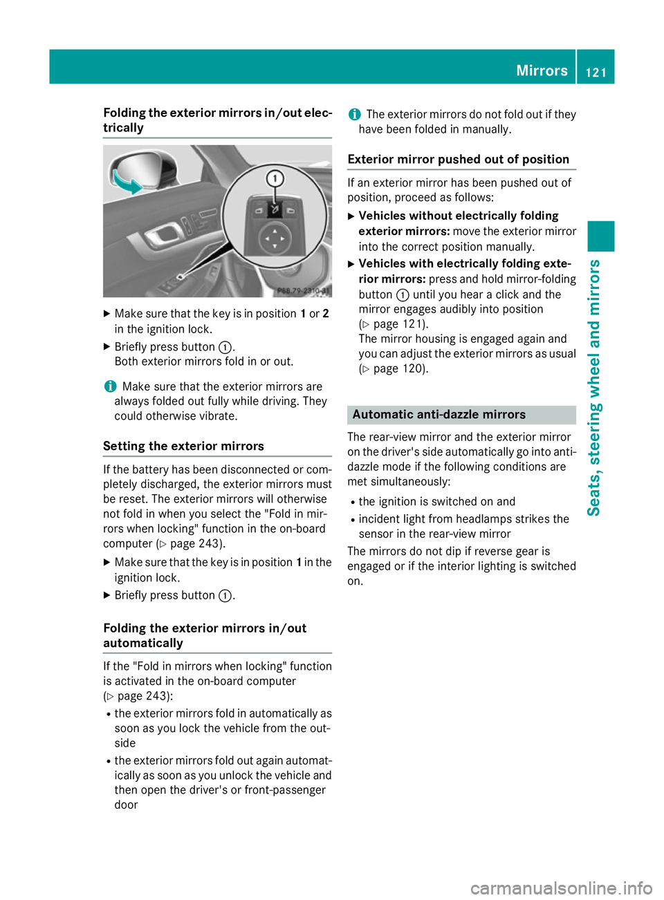
Folding the exterior mirrors in/out elec-
trically X
Make sure that the key is in position 1or 2
in the ignition lock.
X Briefly press button :.
Both exterior mirrors fold in or out.
i Make sure that the exterior mirrors are
always folded out fully while driving. They
could otherwise vibrate.
Setting the exterior mirrors If the battery has been disconnected or com-
pletely discharged, the exterior mirrors must
be reset. The exterior mirrors will otherwise
not fold in when you select the "Fold in mir-
rors when locking" function in the on-board
computer (Y page 243).
X Make sure that the key is in position 1in the
ignition lock.
X Briefly press button :.
Folding the exterior mirrors in/out
automatically If the "Fold in mirrors when locking" function
is activated in the on-board computer
(Y page 243):
R the exterior mirrors fold in automatically as
soon as you lock the vehicle from the out-
side
R the exterior mirrors fold out again automat-
ically as soon as you unlock the vehicle and
then open the driver's or front-passenger
door i
The exterior mirrors do not fold out if they
have been folded in manually.
Exterior mirror pushed out of position If an exterior mirror has been pushed out of
position, proceed as follows:
X Vehicles without electrically folding
exterior mirrors: move the exterior mirror
into the correct position manually.
X Vehicles with electrically folding exte-
rior mirrors: press and hold mirror-folding
button :until you hear a click and the
mirror engages audibly into position
(Y page 121).
The mirror housing is engaged again and
you can adjust the exterior mirrors as usual
(Y page 120). Automatic anti-dazzle mirrors
The rear-view mirror and the exterior mirror
on the driver's side automatically go into anti- dazzle mode if the following conditions are
met simultaneously:
R the ignition is switched on and
R incident light from headlamps strikes the
sensor in the rear-view mirror
The mirrors do not dip if reverse gear is
engaged or if the interior lighting is switched
on. Mirrors
121Seats, steering wheel and mirrors Z
Page 214 of 637
X
Stop the movement of the multifunction
steering wheel or steer yourself.
Active Parking Assist will be cancelled at
once. The Park Assist cancelled
Park Assist cancelled mes-
sage appears in the multifunction display.
or X Press the PARKTRONIC button on the
centre console (Y page 206).
PARKTRONIC is switched off and Active
Parking Assist is immediately cancelled.
The Park Assist cancelled Park Assist cancelled message
appears in the multifunction display.
Active Parking Assist is cancelled automati-
cally if:
R parking using Active Parking Assist is no
longer possible
R you are driving faster than 10 km/h
R a wheel spins and ESP ®
intervenes or fails.
The ÷ ESP®
warning lamp lights up in
the instrument cluster.
A warning tone sounds. The parking symbol
goes out and the Park Assist cancelled
Park Assist cancelled
message appears in the multifunction dis-
play.
When Active Parking Assist is cancelled, you
must steer again yourself. Reversing camera
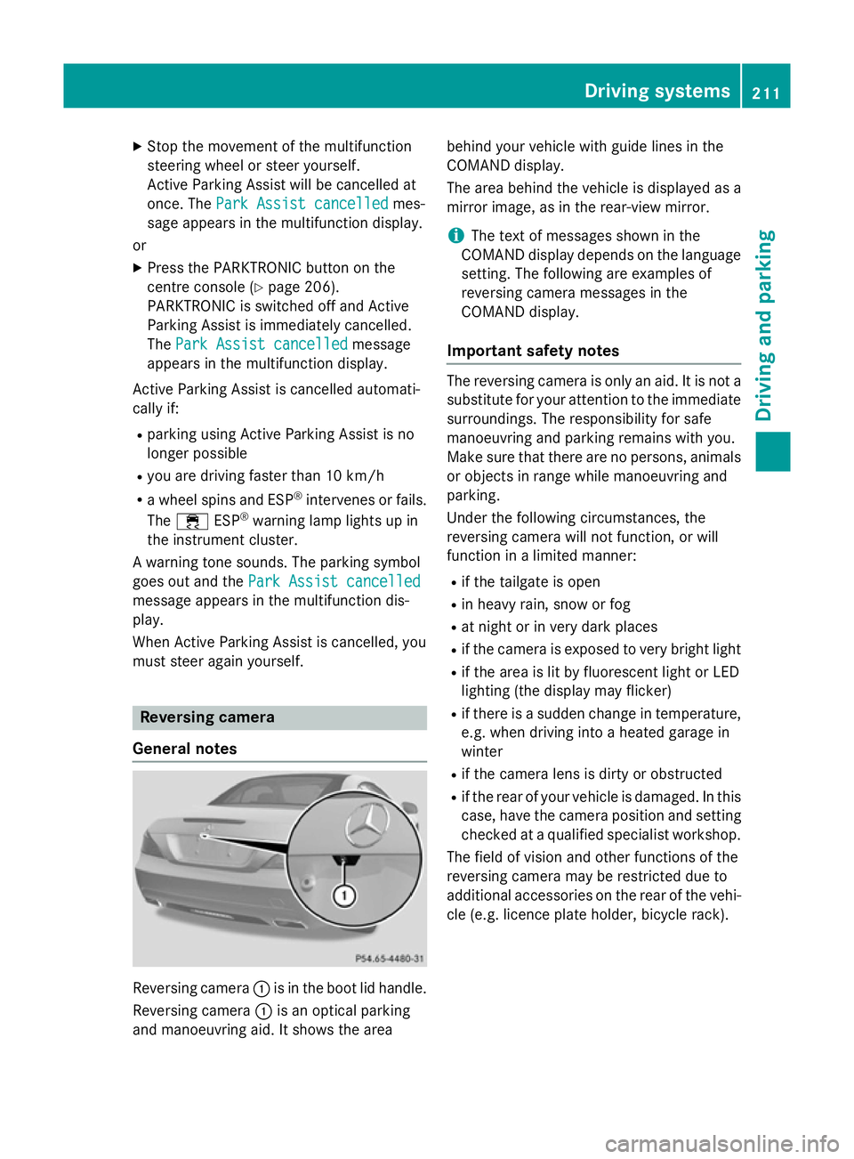
General notes Reversing camera
:is in the boot lid handle.
Reversing camera :is an optical parking
and manoeuvring aid. It shows the area behind your vehicle with guide lines in the
COMAND display.
The area behind the vehicle is displayed as a
mirror image, as in the rear-view mirror.
i The text of messages shown in the
COMAND display depends on the language
setting. The following are examples of
reversing camera messages in the
COMAND display.
Important safety notes The reversing camera is only an aid. It is not a
substitute for your attention to the immediate surroundings. The responsibility for safe
manoeuvring and parking remains with you.
Make sure that there are no persons, animals
or objects in range while manoeuvring and
parking.
Under the following circumstances, the
reversing camera will not function, or will
function in a limited manner:
R if the tailgate is open
R in heavy rain, snow or fog
R at night or in very dark places
R if the camera is exposed to very bright light
R if the area is lit by fluorescent light or LED
lighting (the display may flicker)
R if there is a sudden change in temperature,
e.g. when driving into a heated garage in
winter
R if the camera lens is dirty or obstructed
R if the rear of your vehicle is damaged. In this
case, have the camera position and setting checked at a qualified specialist workshop.
The field of vision and other functions of the
reversing camera may be restricted due to
additional accessories on the rear of the vehi-
cle (e.g. licence plate holder, bicycle rack). Driving systems
211Driving and parking Z
Page 215 of 637
Activating/deactivating the reversing
camera X
To activate: make sure that the key is in
position 2in the ignition lock.
X Make sure that the function "show revers-
ing camera display" is selected in COMAND Online (Y page 322).
X Engage reverse gear.
The area behind the vehicle is shown with
guide lines in the COMAND display.
To deactivate: the reversing camera deacti-
vates if you shift the transmission to Por after
driving forwards a short distance.
Displays in the COMAND display The reversing camera may show a distorted
view of obstacles or show them incorrectly or
not at all. Obstacles are not shown by the
reversing camera in the following locations:
R very close to the rear bumper
R under the rear bumper
R in the area immediately above the tailgate
handle
! Objects not at ground level may appear to
be further away than they actually are, e.g.:
R the bumper of a parked vehicle
R the drawbar of a trailer
R the ball coupling of a trailer tow hitch
R the rear section of an HGV
R a slanted post
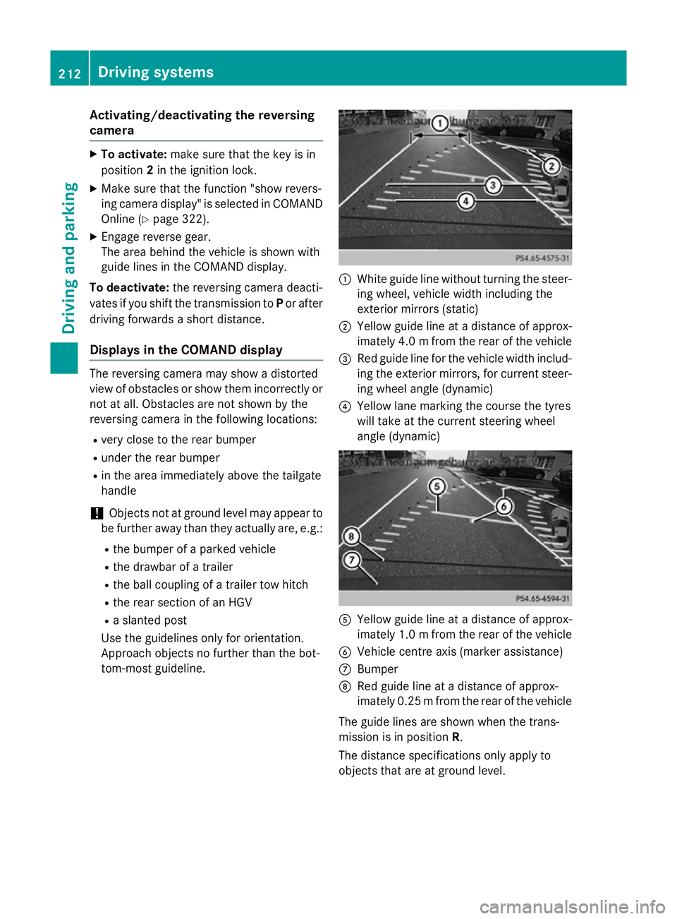
Use the guidelines only for orientation.
Approach objects no further than the bot-
tom-most guideline. :
White guide line without turning the steer-
ing wheel, vehicle width including the
exterior mirrors (static)
; Yellow guide line at a distance of approx-
imately 4.0 mfrom the rear of the vehicle
= Red guide line for the vehicle width includ-
ing the exterior mirrors, for current steer- ing wheel angle (dynamic)
? Yellow lane marking the course the tyres
will take at the current steering wheel
angle (dynamic) A
Yellow guide line at a distance of approx-
imately 1.0 mfrom the rear of the vehicle
B Vehicle centre axis (marker assistance)
C Bumper
D Red guide line at a distance of approx-
imately 0.25 mfrom the rear of the vehicle
The guide lines are shown when the trans-
mission is in position R.
The distance specifications only apply to
objects that are at ground level. 212
Driving systemsDriving and parking
Page 556 of 637
will find further information on charging the
battery on (Y page 582). Garage door opener
General notes The HomeLink
®
garage door opener integra-
ted in the rear-view mirror allows you to oper- ate up to three different door and gate sys-
tems.
Once programmed, the integrated garage
door opener in the rear-view mirror will
assume the function of the garage door sys-
tem's remote control. Please also read the
operating instructions for the garage door
system.
When programming a garage door opener,
park the vehicle outside the garage. Do not
run the engine while programming.
The garage door opener is only available for
certain countries. Observe the legal require-
ments for each individual country.
The HomeLink ®
garage door opener is com-
patible with most European garage and gate
opener drives. More information on Home-
Link ®
and/or compatible products is availa-
ble:
R at a qualified specialised workshop
R via the HomeLink ®
Hotline
(0) 08000 466 354 65 or alternatively
+49 (0) 6838 907-277
R on the Internet at
http://www.homelink.com
Important safety notes G
WARNING
When you operate or program the garage door with the integrated garage door opener, per-
sons in the range of movement of the garage
door can become trapped or struck by the
garage door. There is a risk of injury.
When using the integrated garage door
opener, always make sure that nobody is within the range of movement of the garage
door.
G
WARNING
Combustion engines emit poisonous exhaust
gases such as carbon monoxide. Inhaling
these exhaust gases leads to poisoning. There is a risk of fatal injury. Therefore never leave
the engine running in enclosed spaces with-
out sufficient ventilation.
Programming Programming buttons
Pay attention to the "Important safety notes"
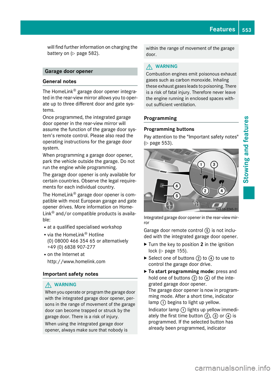
(Y page 553). Integrated garage door opener in the rear-view mir-
ror
Garage door remote control Ais not inclu-
ded with the integrated garage door opener.
X Turn the key to position 2in the ignition
lock (Y page 155).
X Select one of buttons ;to? to use to
control the garage door drive.
X To start programming mode: press and
hold one of buttons ;to? of the inte-
grated garage door opener.
The garage door opener is now in program-
ming mode. After a short time, indicator
lamp :begins to light up yellow.
Indicator lamp :lights up yellow immedi-
ately the first time button ;,=or? is
programmed. If the selected button has
already been programmed, indicator Features
553Stowing and features Z
Page 557 of 637
lamp
:lights up yellow after ten seconds
have elapsed.
X Release button ;,=or?. Indicator
lamp :flashes yellow.
X To program the remote control: point
garage door remote control Atowards
buttons ;to? on the rear-view mirror at
a distance of 5 to 20 cm.
X Press and hold button Bon remote control
A until indicator lamp :lights up green.
When indicator lamp :lights up green:
programming is finished.
When indicator lamp :flashes green: pro-
gramming was successful. The next step is to synchronise the rolling code.
X Release button Bof remote control Aof
the garage door drive.
If indicator lamp :lights up red: repeat the
programming process for the correspond-
ing button on the rear-view mirror. When
doing so, vary the distance between remote
control Aand the rear-view mirror.
The required distance between remote
control Aand the integrated garage door
opener depends on the garage door drive
system. Several attempts may be required.
You should test every position for at least
25 seconds before trying another position.
Synchronising the rolling code
Pay attention to the "Important safety notes"
(Y page 553).
If the garage door system uses a rolling code, you will also have to synchronise the garage
door system with the integrated garage door
opener in the rear-view mirror. To do this you
will need to use the programming button on
the door drive control panel. Depending on
the manufacturer, the location of the pro-
gramming button may vary. It is usually loca-
ted on the door drive unit on the garage ceil-
ing.
Familiarise yourself with the garage door
drive operating instructions, e.g. under "Pro-
gramming of additional remote controls",
before carrying out the following steps. Your vehicle must be within range of the
garage door or exterior gate drive. Make sure
that neither your vehicle nor any persons/
objects are present within the sweep of the
door or gate.
X Turn the key to position 2in the ignition
lock (Y page 155).
X Get out of the vehicle.
X Press the programming button on the door
drive unit.
Usually, you now have 30 seconds to ini-
tiate the next step.
X Get into the vehicle.
X Press previously programmed button ;,
= or? of the integrated garage door
opener until the door closes.
The rolling code synchronisation is then
complete.
Problems when programming
If you have problems when programming the
integrated garage door opener, please note
the following:
R Check the transmitter frequency used by
garage door drive remote control Aand
whether it is supported. The transmitter
frequency can usually be found on the back
of the garage door drive remote control.
R Replace the batteries in garage door
remote control A. This increases the like-
lihood that garage door remote control A
will transmit a strong and precise signal to the integrated garage door opener in the
rear-view mirror.
R When programming, hold remote control
A at varying distances and angles from the
button which you are programming. Try var- ious angles at a distance between 5and
30 cm or at the same angle but at varying
distances.
R If there is another remote control for the
same garage door drive, perform the pro-
gramming steps again using this remote
control. Before performing these steps,
make sure that new batteries have been 554
FeaturesStowing and features
Page 558 of 637
fitted in garage door drive remote control
A.
R Note that some remote controls transmit
only for a limited period (the indicator lamp
on the remote control goes out). Press but- ton Bon remote control Aagain before
transmission ends.
R Align the aerial cable of the garage door
opener unit. This can improve signal recep-
tion/transmission.
Opening or closing the garage door Once programmed, the integrated garage
door opener will assume the function of the
garage door system's remote control. Please
also read the operating instructions for the
garage door system.
X Turn the key to position 2in the ignition
lock (Y page 155).
X Press button ;,=or? which you have
programmed to operate the garage door.
Garage door system with a fixed code: indi-
cator lamp :lights up green.
Garage door system with a rolling code:
indicator lamp :flashes green.
The transmitter will transmit a signal for as
long as the button is pressed. The transmis-
sion is halted after a maximum of ten seconds
and indicator lamp :lights up yellow. Press
button ;,=or? again if necessary.
Clearing the memory Make sure that you clear the memory of the
integrated garage door opener before selling
the vehicle.
X Turn the key to position 2in the ignition
lock (Y page 155).
X Press and hold buttons ;and ?.
The indicator lamp first lights up yellow and then green.
X Release buttons ;and ?.
The memory of the integrated garage door
opener in the rear-view mirror is cleared. Frequencies Europe
Country Radio type approval num-
ber
Frequency range (MHz)
AD (Andorra) 20 July 2005
MHz: 27, 30, 40, 433, 868
AT (Austria) Article 6 of Directive
1999/5/EC R&TTE 18 May
05
MHz: 27, 40, 433, 868
BE (Belgium) Article 6 of Directive
1999/5/EC R&TTE 18 May
05
MHz: 27, 40, 433, 868
BG (Bulga-
ria) Article 6 of Directive
1999/5/EC R&TTE 12 April
07
MHz: 27, 40, 433, 868 CH (Switzer-
land) Article 6 of Directive
1999/5/EC R&TTE 14357
27 May 05
MHz: 27, 40, 433, 868
CY (Cyprus) Article 6 of Directive
1999/5/EC R&TTE 5 May
05
MHz: 27, 40, 433, 868
CZ (Czech
Republic) General Licence GL-30/R/
2000 Reg No. 844 13 May
05
MHz: 27, 40, 433
DK (Den-
mark) Article 6 of Directive
1999/5/EC R&TTE 20 April
05
MHz: 27, 40, 433, 868 DE (Ger-
many) Article 6 of Directive
1999/5/EC R&TTE
7519301 29 April 05
MHz: 27, 40, 433, 868 Features
555Stowing and features Z