2012 MERCEDES-BENZ SL ROADSTER set clock
[x] Cancel search: set clockPage 148 of 637
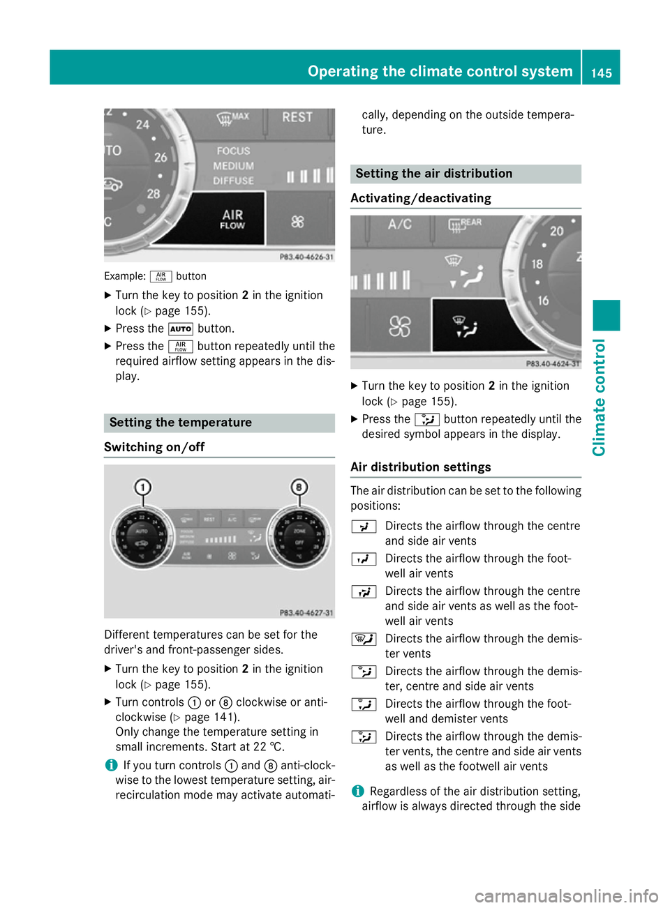
Example:
ñbutton
X Turn the key to position 2in the ignition
lock (Y page 155).
X Press the Ãbutton.
X Press the ñbutton repeatedly until the
required airflow setting appears in the dis-
play. Setting the temperature
Switching on/off Different temperatures can be set for the
driver's and front-passenger sides.
X Turn the key to position 2in the ignition
lock (Y page 155).
X Turn controls :orD clockwise or anti-
clockwise (Y page 141).
Only change the temperature setting in
small increments. Start at 22 †.
i If you turn controls
:and Danti-clock-
wise to the lowest temperature setting, air- recirculation mode may activate automati- cally, depending on the outside tempera-
ture. Setting the air distribution
Activating/deactivating X
Turn the key to position 2in the ignition
lock (Y page 155).
X Press the _button repeatedly until the
desired symbol appears in the display.
Air distribution settings The air distribution can be set to the following
positions:
P Directs the airflow through the centre
and side air vents
O Directs the airflow through the foot-
well air vents
S Directs the airflow through the centre
and side air vents as well as the foot-
well air vents
¯ Directs the airflow through the demis-
ter vents
b Directs the airflow through the demis-
ter, centre and side air vents
a Directs the airflow through the foot-
well and demister vents
_ Directs the airflow through the demis-
ter vents, the centre and side air vents
as well as the footwell air vents
i Regardless of the air distribution setting,
airflow is always directed through the side Operating the climate control system
145Climate control
Page 150 of 637
Air-recirculation mode remains deactiva-
ted.
or
X Press the Ãbutton.
The indicator lamp in the ¬button goes
out. Airflow and air distribution are set to
automatic mode.
or X Turn the temperature controls on the left or
the right on the climate control panel clock- wise or anti-clockwise.
Turn temperature controls :orD clock-
wise or anti-clockwise (Y page 141).
or
X Press the KorI button. Demisting the windows
Windows misted up on the inside X
Activate the ¿cooling with air dehu-
midification function.
X Activate the Ãmode button.
X If the windows continue to mist up, activate
the ¬ "Windscreen demisting" function.
i You should only select this setting until
the windscreen is clear again.
Windows misted up on the outside X
Activate the windscreen wipers.
X Press the _button repeatedly until the
P orO symbol appears in the dis-
play.
i You should only select this setting until
the windscreen is clear again. Rear window heating
General notes The rear window heating has a high current
draw. You should therefore switch it off as
soon as the window is clear. It otherwise
switches off automatically after several
minutes.
If the battery voltage is too low, the rear win-
dow heating may switch off.
Activating/deactivating X
Turn the key to position 2in the ignition
lock (Y page 155).
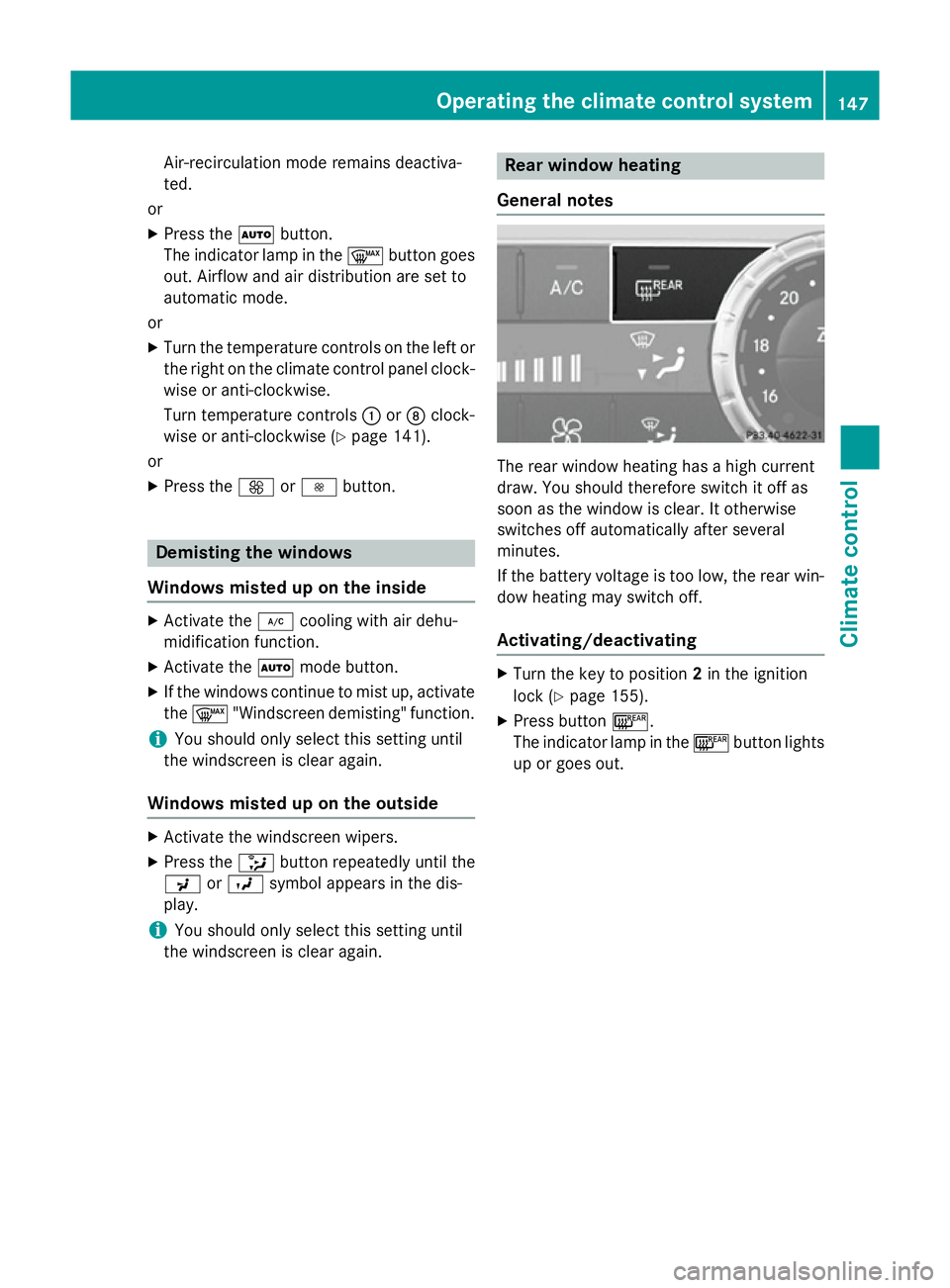
X Press button ¤.
The indicator lamp in the ¤button lights
up or goes out. Operating the climate control system
147Climate control
Page 153 of 637
Residual heat is deactivated automatically:
R after approximately 30 minutes
R when the ignition is switched on
R if the battery voltage drops Adjusting the air vents
Important safety notes
G
WARNING
Very hot or very cold air can flow from the air vents. This could result in burns or frostbite in the immediate vicinity of the air vents. There
is a risk of injury.
Make sure that all vehicle occupants always
maintain a sufficient distance to the air out-
lets. If necessary, redirect the airflow to
another area of the vehicle interior. G
WARNING
When AIRSCARF is switched on, very hot air
can flow from the vents in the head restraints. This could result in burns in the immediate
vicinity of the air vents. There is a risk of injury.
Reduce the heater output before it becomes
too hot.
In order to ensure the direct flow of fresh air
through the air vents into the vehicle interior, please observe the following notes:
R keep the air inlet grille on the bonnet and in
the engine compartment on the front-
passenger side free of blockages, such as
ice, snow or leaves.
R never cover the vents or ventilation grilles
in the vehicle interior.
i You can move the adjusters for the air
vents vertically or horizontally to set the
direction of the airflow.
i Optimal climate control function is ach-
ieved by opening the air vents fully and set-
ting the adjusters to the middle position. Setting the centre air vents
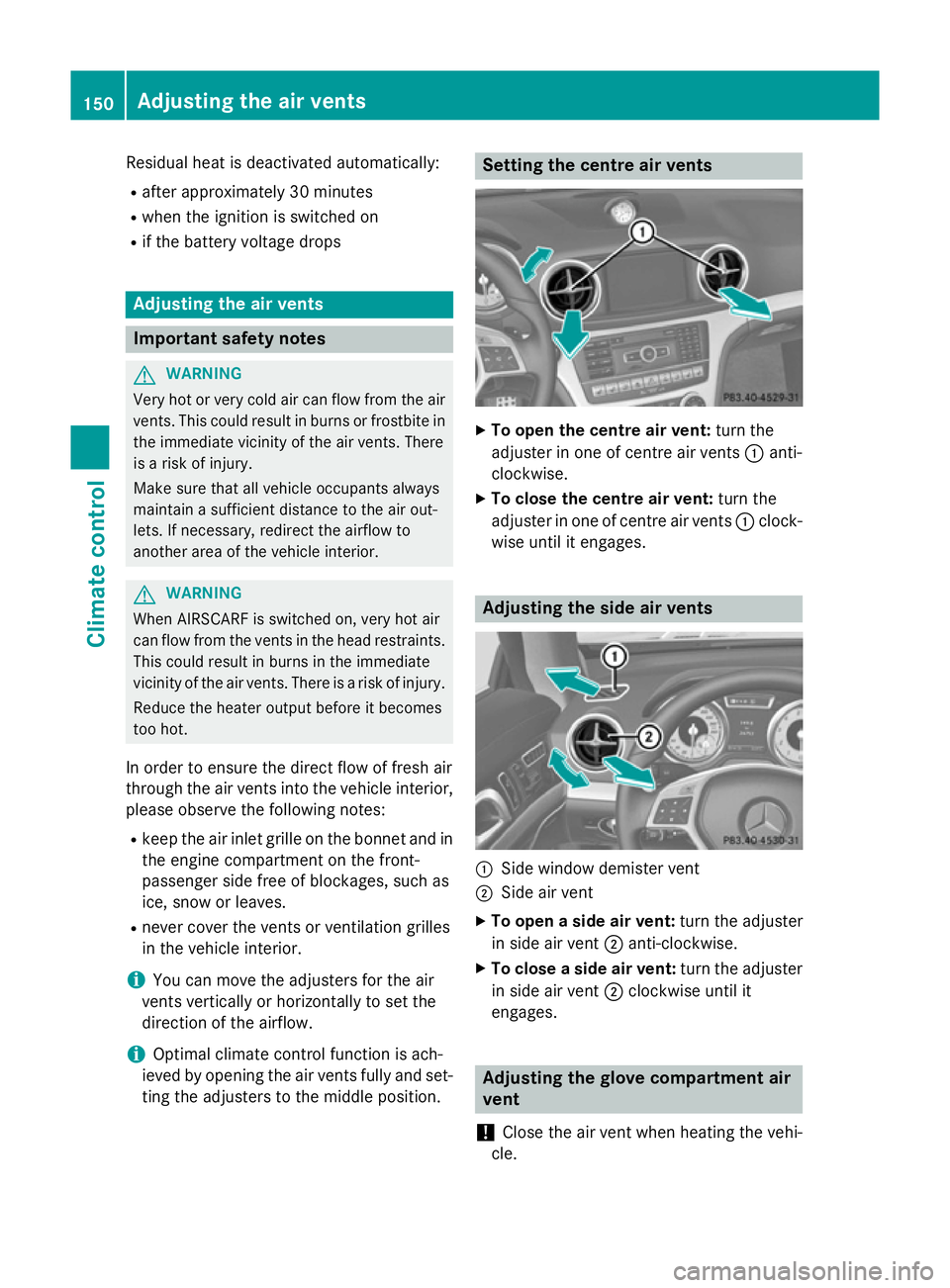
X
To open the centre air vent: turn the
adjuster in one of centre air vents :anti-
clockwise.
X To close the centre air vent: turn the
adjuster in one of centre air vents :clock-
wise until it engages. Adjusting the side air vents
:
Side window demister vent
; Side air vent
X To open a side air vent: turn the adjuster
in side air vent ;anti-clockwise.
X To close a side air vent: turn the adjuster
in side air vent ;clockwise until it
engages. Adjusting the glove compartment air
vent
! Close the air vent when heating the vehi-
cle. 150
Adjusting the air ventsClimate cont
rol
Page 154 of 637
At high outside temperatures, open the air
vent and activate the "cooling with air dehu- midification" function. Otherwise, temper-
ature-sensitive items stored in the glove
compartment could be damaged. :
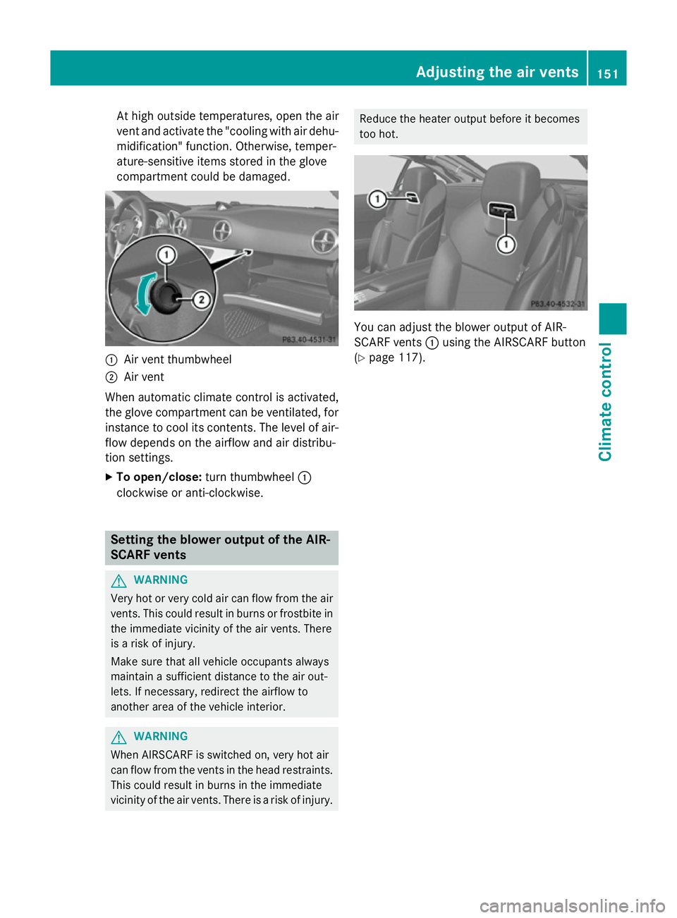
Air vent thumbwheel
; Air vent
When automatic climate control is activated,
the glove compartment can be ventilated, for
instance to cool its contents. The level of air-
flow depends on the airflow and air distribu-
tion settings.
X To open/close: turn thumbwheel :
clockwise or anti-clockwise. Setting the blower output of the AIR-
SCARF vents G
WARNING
Very hot or very cold air can flow from the air vents. This could result in burns or frostbite in the immediate vicinity of the air vents. There
is a risk of injury.
Make sure that all vehicle occupants always
maintain a sufficient distance to the air out-
lets. If necessary, redirect the airflow to
another area of the vehicle interior. G
WARNING
When AIRSCARF is switched on, very hot air
can flow from the vents in the head restraints. This could result in burns in the immediate
vicinity of the air vents. There is a risk of injury. Reduce the heater output before it becomes
too hot.
You can adjust the blower output of AIR-
SCARF vents
:using the AIRSCARF button
(Y page 117). Adjusting the air vents
151Climate control Z
Page 231 of 637
Useful information
i This Owner's Manual describes all mod-
els, series and optional equipment for your
vehicle that were available at the time of
going to press. National variations are pos- sible. Note that your vehicle may not be
equipped with all of the functions descri-
bed. This is also the case for systems and
functions relevant to safety.
i Read the information on qualified special-
ist workshops: (Y page 34). Important safety notes
G
WARNING
Operating the integrated information systems and communications equipment in the vehicle
while driving will distract you from traffic con-
ditions. You could then lose control of the
vehicle. There is a risk of an accident.
Only operate these devices if road traffic con-
ditions permit. If you are unsure about the
surrounding conditions, pull over to a safe
location and make entries only while the vehi-
cle is stationary. G
WARNING
If the instrument cluster has failed or mal-
functioned, you may not recognise function
restrictions relevant to safety. The operating
safety of your vehicle may be impaired. There is a risk of an accident.
Drive on carefully. Have the vehicle checked
at a qualified specialist workshop immedi-
ately.
You must observe the legal requirements for
the country in which you are currently driving when operating the on-board computer.
The on-board computer only shows messages
or warnings from certain systems in the mul- tifunction display. You should therefore make
sure your vehicle is operating safely at all times. Otherwise, a vehicle that is not oper-
ating safely may cause an accident.
For an overview, see the instrument panel
illustration (Y
page 40). Displays and operation
Instrument cluster lighting
The lighting in the instrument cluster, in the
displays and the controls in the vehicle inte-
rior can be adjusted using the brightness con- trol knob.
The brightness control knob is on the bottom
left of the instrument cluster (Y page 40).
X Turn the brightness control knob anti-
clockwise or clockwise.
If the light switch is set to Ã,Tor
L, the brightness is dependant upon
the brightness of the ambient light.
i The light sensor in the instrument cluster
automatically controls the brightness of
the multifunction display.
In daylight, the displays in the instrument
cluster are not lit. Coolant temperature gauge
G
WARNING
If you open the bonnet while the engine is
overheating or while there is a fire in the
engine compartment, you could come into
contact with hot gases or other leaking ser-
vice products. There is a danger of injury.
Allow an overheating engine to cool down
before opening the bonnet. If there is a fire in the engine compartment, leave the bonnet
closed and notify the fire brigade.
The coolant temperature gauge is in the
instrument cluster on the right-hand side
(Y page 40).
Under normal operating conditions and with
the specified coolant level, the coolant tem-
perature may rise to 120 †. 228
Displays and operationOn-board computer and displays
Page 317 of 637
You can select the following predefined func-
tions in a menu:
R SplitView on/off
SplitView on/off: you can switch the
screen view for the front passenger on or
off.
R Display off/on
Display off/on: you can switch the dis-
play off or on.
R Full screen: 'Clock' Full screen: 'Clock': you can call up
the full screen with the clock.
R ® Menu
Menu : you can call up the COMAND
Online and Internet functions.
R 360°
360° camera
camera: you can call up the picture of
the 360° camera.
R Full screen: 'Map'
Full screen: 'Map' : you can call up the
full screen with the map.
R Spoken driving tip
Spoken driving tip : you can call up the
current driving recommendation.
R Display
Display traffic
trafficmessages
messages: you can call
up traffic reports.
R Navigate to 'Home address'
Navigate to 'Home address' : you can
start route guidance to your home address
if you have already entered and saved the
address (Y page 330).
R Detour menu
Detour menu : you can call up the Detour
menu and then block a section of the route
and recalculate the route (Y page 357).
R Compass
Compass screen
screen: you can call up the com-
pass. Importing/exporting data
General notes !
When data is being copied to the USB
stick or the memory card, the stick or the
card must not be removed under any cir-
cumstances. Doing so runs the risk of data loss. Using this function, you can:
R transfer your personal COMAND data from
one system/vehicle to another
R make a backup copy of your personal data
(export data) and load it again (import
data).
R protect your data from unwanted export by
activating a pin prompt (presetting: deacti-
vated ª).
You can either use an SD memory card or a
USB storage device (e.g. a USB stick) as tem- porary storage.
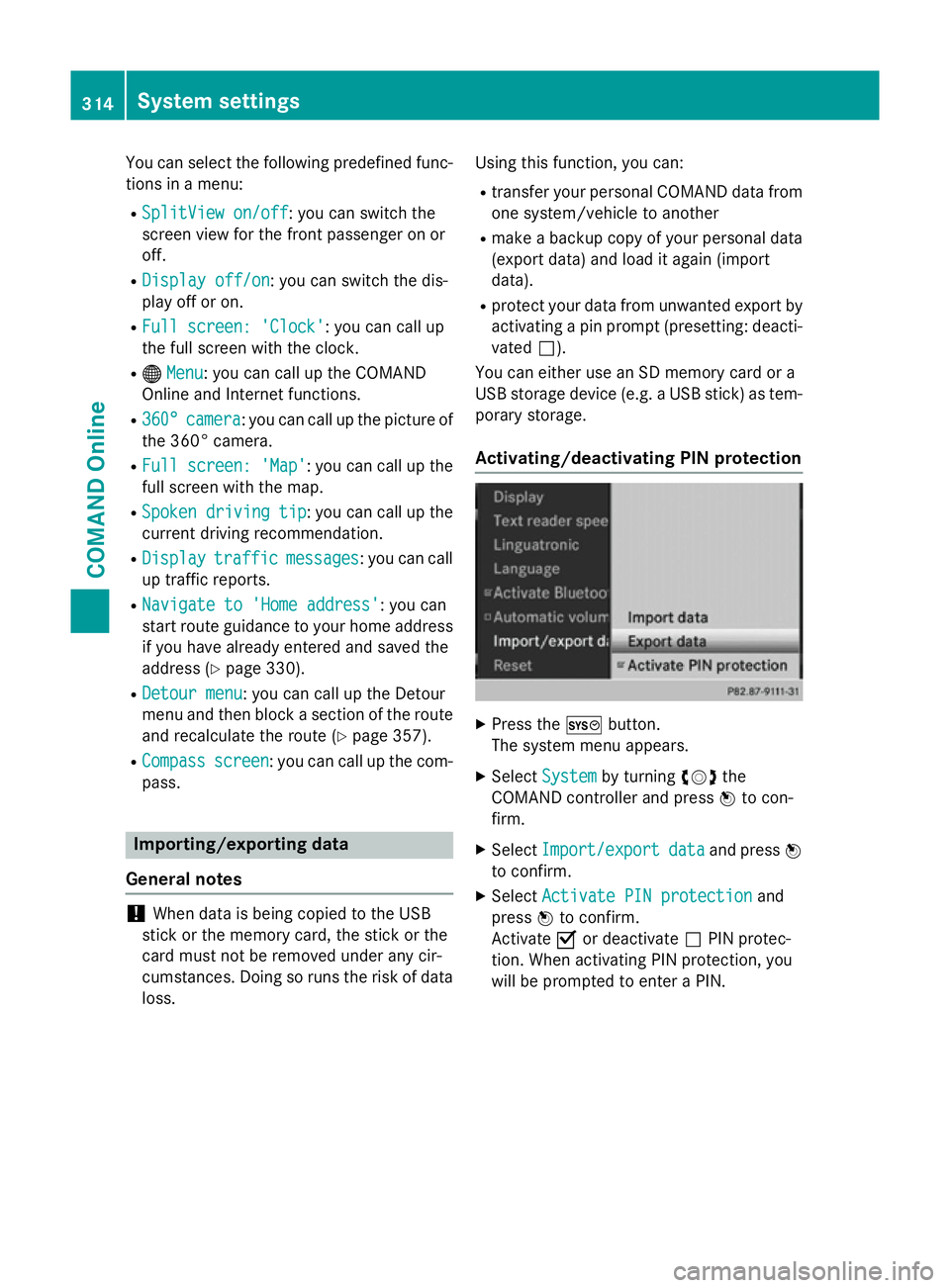
Activating/deactivating PIN protection X
Press the Wbutton.
The system menu appears.
X Select System
System by turning cVdthe
COMAND controller and press Wto con-
firm.
X Select Import/export Import/export data
dataand press W
to confirm.
X Select Activate PIN protection
Activate PIN protection and
press Wto confirm.
Activate Oor deactivate ªPIN protec-
tion. When activating PIN protection, you
will be prompted to enter a PIN. 314
System settingsCOMAND Online
Page 321 of 637
X
To call up the full-screen display: press
the W button.
X In the system menu, slide ZVthe
COMAND controller up until the Full Full
screen screen option is selected.
X Press Wthe COMAND controller.
The system display is shown as full screen
(without system menu).
X Slide XVY the COMAND controller repeat-
edly until the fuel consumption indicator
appears.
The COMAND display shows the fuel con-
sumption for the last 15 minutes of the
journey.
X To exit the full-screen display: pressW
the COMAND controller.
The system menu appears.
Every bar of the graph displays the average
value for one minute.
The fuel consumption display may differ from
the display in the FROM START FROM STARTtrip computer
in the Trip
Trip menu; see the vehicle Owner's
Manual. Driving conditions menu (Active Body
Control)
General notes On vehicles with Active Body Control (ABC),
you can display some driving systems and
additional information in the COMAND dis-
play.
Calling up drive status regulator (ABC) X
Press W.
X In the system menu, slide ZVthe
COMAND controller up until the display/
selection window is selected.
X Slide XVY the COMAND controller repeat-
edly until the drive status regulator (ABC)
appears.
The corresponding displays appear in the
COMAND display. Details on the displays:
R for vehicles except AMG vehicles; see the
separate vehicle Owner's Manual
R for AMG vehicles; see the separate vehicle
Owner's Manual
Exiting the display X
Slide XVY the COMAND controller until
the desired display (clock or fuel consump-
tion) is shown. Seat functions
Overview Using the
Tbutton next to the COMAND
controller or the Seat menu item in the sys-
tem menu, you can call up different setting
functions: The following settings depend on
the type of seat and the vehicle model series:
R seat cushion length
R backrest side bolsters
R lumbar
R balance
R cushion side bolsters
R driving dynamics
R massage
i You also can save and recall the current
settings of a seat function using the mem-
ory button and the corresponding memory
position switch; see the separate vehicle
Owner's Manual.
The massage function cannot be started or
stopped using the memory button. 318
Vehicle functionsCOMAND Online
Page 337 of 637
Moving the map and selecting the desti-
nation
X Call up the destination entry via the map
(Y page 333).
X To scroll the map: slideXVY, ZVÆor
aVb the COMAND controller.
X To set the map scale: as soon as you turn
cVd the COMAND controller, the scale bar
appears.
X Turn cVd until the desired scale is set.
Turning clockwise zooms out from the map; turning anti-clockwise zooms in.
X To select a destination: pressWthe
COMAND controller.
If the crosshair lies outside the digital map,
COMAND Online uses the nearest digitised
road for route calculation. The The
The cross‐ cross‐
hair is outside the digitalised
hair is outside the digitalised
area area of
ofthe
the map
mapmessage is shown. If the
crosshair is located over a body of water,
you will see the message: The destina‐ The destina‐
tion is located in a body of
tion is located in a body of
water. Please select another des‐ water. Please select another des‐
tination.
tination.
X Select OK
OKand press Wto confirm.
If the destination is within the limits of the
digital map, COMAND Online attempts to
assign the destination to the map.
If the destination can be assigned, you will see the address entry menu with the
address of the destination. If not, you will
see the Destination from map
Destination from map entry.
X To start route calculation: selectStart
Start
and press Wto confirm. Entering a destination using geo-coor-
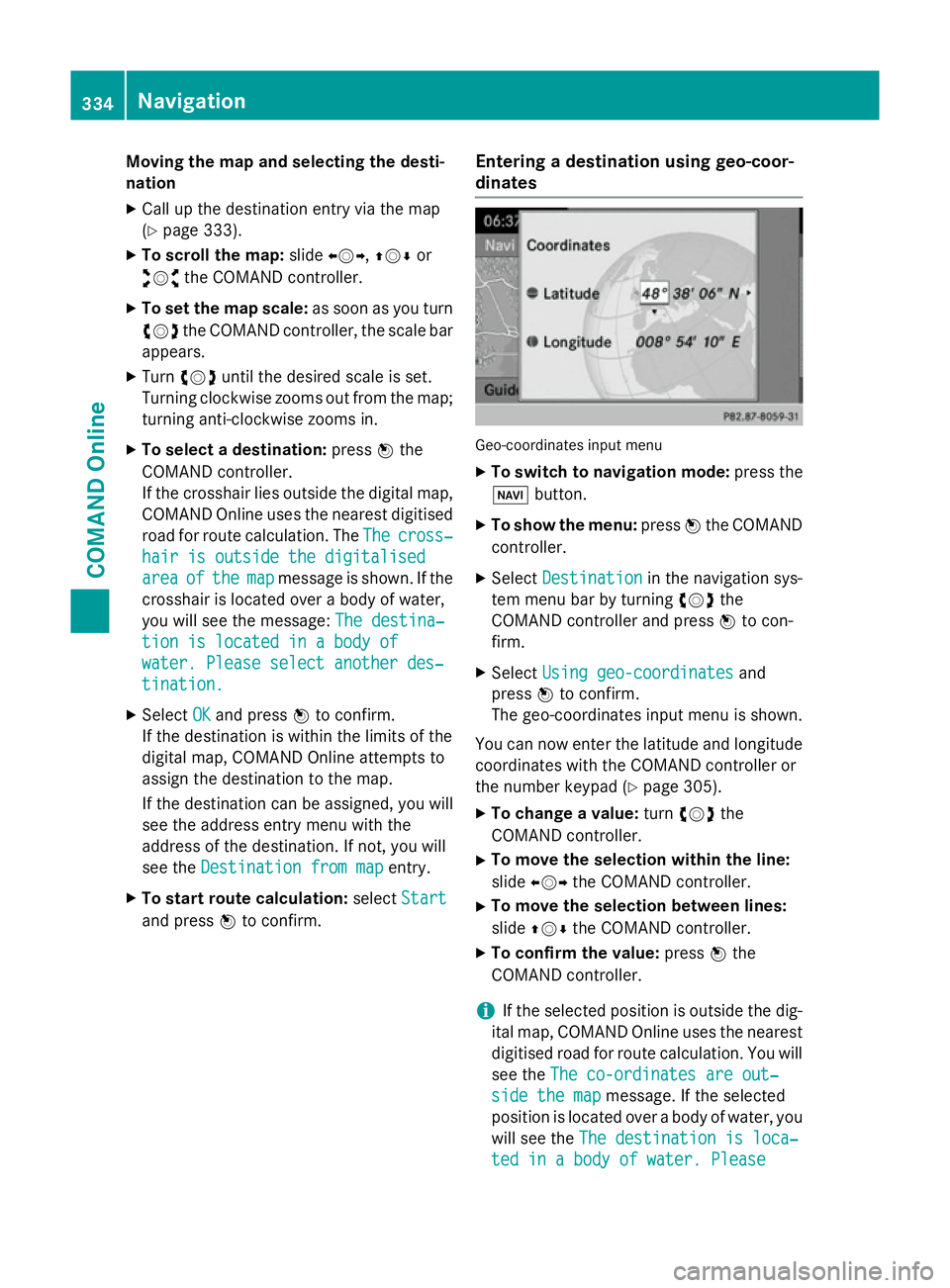
dinates Geo-coordinates input menu
X To switch to navigation mode: press the
Ø button.
X To show the menu: pressWthe COMAND
controller.
X Select Destination Destination in the navigation sys-
tem menu bar by turning cVdthe
COMAND controller and press Wto con-
firm.
X Select Using geo-coordinates
Using geo-coordinates and
press Wto confirm.
The geo-coordinates input menu is shown.
You can now enter the latitude and longitude coordinates with the COMAND controller or
the number keypad (Y page 305).
X To change a value: turncVd the
COMAND controller.
X To move the selection within the line:
slide XVY the COMAND controller.
X To move the selection between lines:
slide ZVÆ the COMAND controller.
X To confirm the value: pressWthe
COMAND controller.
i If the selected position is outside the dig-
ital map, COMAND Online uses the nearest
digitised road for route calculation. You will
see the The co-ordinates are out‐ The co-ordinates are out‐
side the map
side the map message. If the selected
position is located over a body of water, you
will see the The destination is loca‐
The destination is loca‐
ted in a body of water. Please
ted in a body of water. Please 334
NavigationCOMAND Online