2012 MERCEDES-BENZ CLS SHOOTING BRAKE boot
[x] Cancel search: bootPage 297 of 405
X
Vehicles without memory function: if nec-
essary, move the driver's or front-
passenger seat forwards.
X Open the boot.
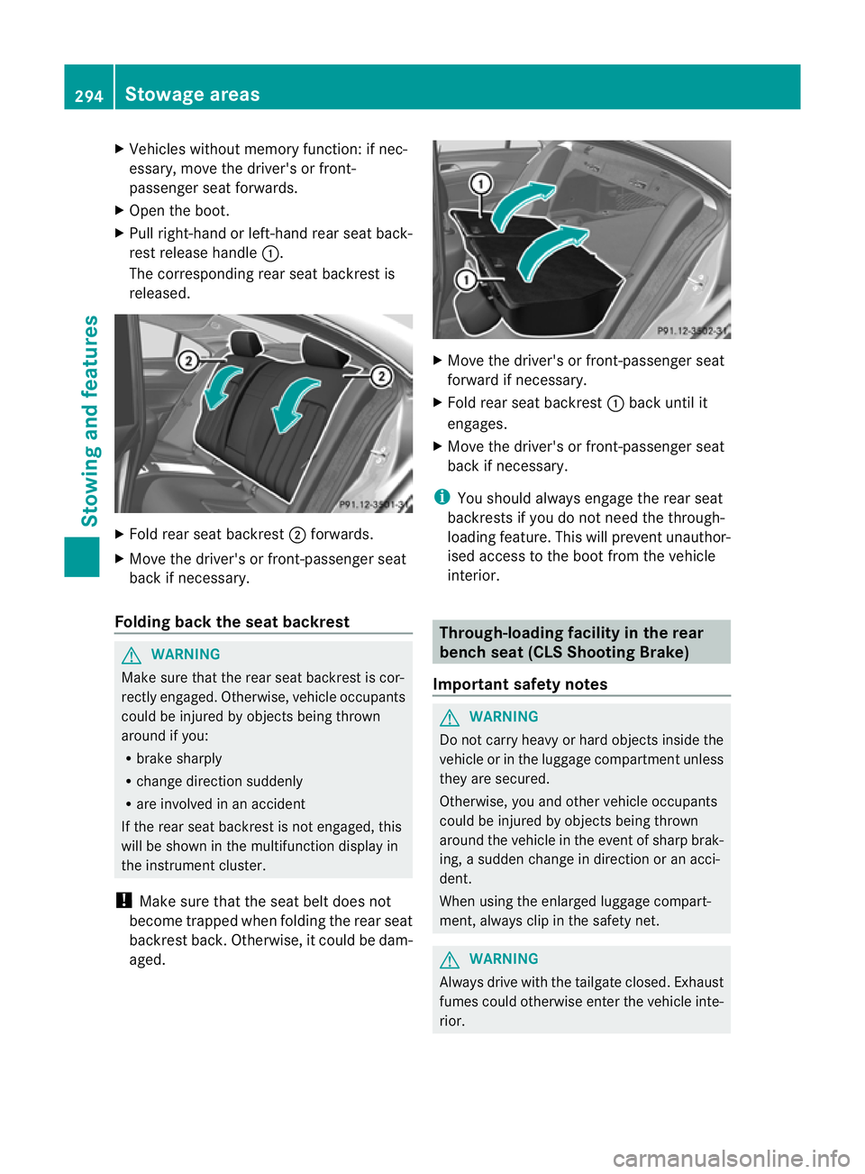
X Pull right-hand or left-hand rear seat back-
rest release handle :.
The corresponding rear seat backrest is
released. X
Fold rear seat backrest ;forwards.
X Move the driver's or front-passenger seat
back if necessary.
Folding back the seat backrest G
WARNING
Make sure that the rear seat backrest is cor-
rectly engaged. Otherwise, vehicle occupants
could be injured by objects being thrown
around if you:
R brake sharply
R change direction suddenly
R are involved in an accident
If the rear seat backrest is not engaged, this
will be shown in the multifunction display in
the instrument cluster.
! Make sure that the seat belt does not
become trapped when folding the rear seat
backrest back. Otherwise, it could be dam-
aged. X
Move the driver's or front-passenger seat
forward if necessary.
X Fold rear seat backrest :back until it
engages.
X Move the driver's or front-passenger seat
back if necessary.
i You should always engage the rear seat
backrests if you do not need the through-
loading feature. This will prevent unauthor-
ised access to the boot from the vehicle
interior. Through-loading facility in the rear
benchs
eat (CLS Shooting Brake)
Important safety notes G
WARNING
Do not carry heavy or hard objects inside the
vehicle or in the luggage compartmen tunless
they are secured.
Otherwise, you and othe rvehicle occupants
could be injured by objects being thrown
around the vehicle in the event of sharp brak-
ing, a sudden change in direction or an acci-
dent.
When using the enlarged luggage compart-
ment, always clip in the safety net. G
WARNING
Always drive with the tailgate closed. Exhaust
fumes could otherwise enter the vehicle inte-
rior. 294
Stowage areasStowing and features
Page 299 of 405
Observe the following notes on securing
loads:
R
secure the load using the lashing eyelets.
R do not use elastic straps or nets to secure
a load, as these are only intended as an
anti-slip protection for light loads.
R do not route lashing materials across sharp
edges or corners.
R pad sharp edges for protection.
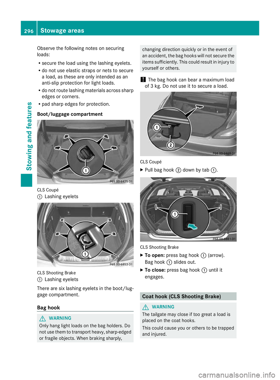
Boot/luggage compartment CLS Coupé
:
Lashing eyelets CLS Shooting Brake
:
Lashing eyelets
There are six lashing eyelets in the boot/lug-
gage compartment.
Bag hook G
WARNING
Only hang light loads on the bag holders. Do
not use them to transport heavy, sharp-edged
or fragile objects. When braking sharply, changing direction quickly or in the event of
an accident, the bag hooks will not secure the
items sufficiently. This could result in injury to
yourselforo
thers.
! The bag hoo kcan bear a maximum load
of 3 kg. Do not use it to secure a load. CLS Coupé
X
Pull bag hook ;down by tab :. CLS Shooting Brake
X To open: press bag hook :(arrow).
Bag hook :slides out.
X To close: press bag hook :until it
engages. Coat hook (CLS Shooting Brake)
G
WARNING
The tailgate may close if too great a load is
placed on the coat hooks.
This could cause you or others to be trapped
and injured. 296
Stowage areasStowing and features
Page 302 of 405
X
To loosen and detach: pull belt
clamp ?up to reduce the tension in the
lashing strap.
X Remove spring hook =from the lashing
eyelet or bracket (vehicles with EASY-PACK
load-securing kit (Y page 300)).
X Detach guide rod :from bracket ;.
X To stow: press the red button on the upper
and lowe rguide rod.
X Fold the safety ne tand roll it up.
X Close the two Velcro fasteners on the
safety net holder. EASY-PACK boot box (CLS Coupé)
Important safety notes G
WARNING
Only load the EASY-PACK convenience bo xto
the maximum permissible load of 10 kg. To
prevent overloading, the floor of the box
moves down onto the boot floor ma twhen
loaded with more than approx. 5kg.
Do not transpor tsharp-edged and fragile
objects in the box.
Otherwise, e.g. in the event of a rapid change
of direction or heavy braking, the objects
could be thrown out of the EASY-PACK con-
venience box and injure you and others.
! When the EASY-PACK convenience box is
pulled out, no objects may be placed on the
frame of the box or pushed onto the frame
from above. Otherwise, the box could be
damaged.
Adjusting the height to any position G
WARNING
Make sure that your hands are not inside the
EASY-PACK convenience box when the load
surface moves up. Otherwise, you could be
injured. X
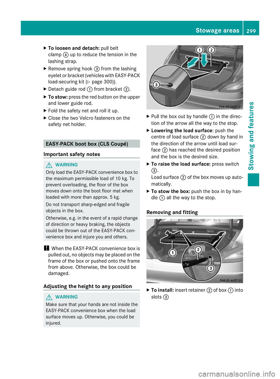
Pull the box out by handle :in the direc-
tion of the arrow all the way to the stop.
X Lowering the load surface:p ush the
centre of load surface ;down by hand in
the direction of the arrow until load sur-
face ;has reached the desired position
and the box is the desired size.
X To raise the load surface: press switch
=.
Load surface ;of the box moves up auto-
matically.
X To stow the box: push the box in by han-
dle :all the way to the stop.
Removing and fitting X
To install: insert retainer ;of box :into
slots = Stowage areas
299Stowing and featu res Z
Page 303 of 405
X
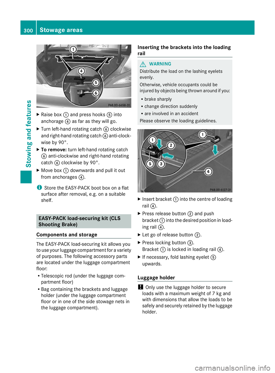
Raise box :and press hooks Ainto
anchorage ?as far as they will go.
X Turn left-hand rotating catch Bclockwise
and right-hand rotating catch Banti-clock-
wise by 90°.
X To remove: turn left-hand rotating catch
B anti-clockwise and right-hand rotating
catch Bclockwise by 90°.
X Move box :downwards and pull it out
from anchorages ?.
i Store the EASY-PACK boot box on a flat
surface after removal, e.g. on a suitable
shelf. EASY-PACK load-securing kit (CLS
Shooting Brake)
Components and storage The EASY-PACK load-securing ki
tallows you
to use your luggage compartmen tfor a variety
of purposes. The following accessory parts
are located under the luggage compartment
floor:
R Telescopic rod (under the luggage com-
partment floor)
R Bag containing the brackets and luggage
holder (under the luggage compartment
floor or in one of the side stowage nets in
the luggage compartment). Inserting the brackets into the loading
rail G
WARNING
Distribute the load on the lashing eyelets
evenly.
Otherwise, vehicle occupants could be
injured by objects being thrown around if you:
R brake sharply
R change direction suddenly
R are involved in an accident
Please observe the loading guidelines. X
Insert bracket :into the centre of loading
rail ?.
X Press release button ;and push
bracket :into the desired position in load-
ing rail ?.
X Let go of release button ;.
X Press locking button =.
Bracket :is locked in loading rail ?.
X If necessary, fold lashing eyelet A
upwards.
Luggage holder !
Only use the luggage holder to secure
loads with a maximum weight of 7kg and
with dimensions that allow the loads to be
safely and securely retained by the luggage
holder. 300
Stowage areasStowing and features
Page 304 of 405
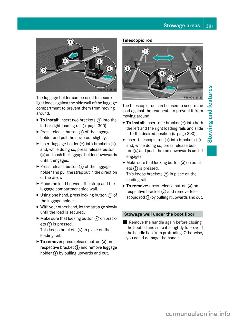
The luggage holder can be used to secure
light loads against the side wall of the luggage
compartment to prevent them from moving
around.
X To install: insert two brackets Ainto the
left or right loading rail (Y page 300).
X Press release button :of the luggage
holder and pull the strap out slightly.
X Insert luggage holder ;into brackets A
and, while doing so, press release button
= and push the luggage holder downwards
until it engages.
X Press release button :of the luggage
holder and pull the strap out in the direction
of the arrow.
X Place the load between the strap and the
luggage compartment side wall.
X Using one hand, press locking button :of
the luggage holder.
X With your other hand, let the strap go slowly
until the load is secured.
X Make sure that locking button ?on brack-
ets Ais pressed.
This keeps brackets Ain place on the
loading rail.
X To remove: press release button =on
respective bracket Aand remove luggage
holder ;by pulling upwards and out. Telescopic rod
The telescopic rod can be used to secure the
load against the rear seats to prevent it from
moving around.
X
To install: insert one bracket ;into both
the left and the right loading rails and slide
it to the desired position (Y page 300).
X Insert telescopic rod :into brackets ;
and, while doing so, press release but-
ton ?and push the rod downwards until it
engages.
X Make sure that locking button =on brack-
ets ;is pressed.
This keeps brackets ;in place on the
loading rail.
X To remove: press release button ?on
respective bracket ;and remove tele-
scopic rod :by pulling it upwards and out. Stowage well under the boot floor
! Remove the handle again before closing
the boot lid and snap it in tightly to prevent
the handle flap from protruding. Otherwise,
you could damage the handle. Stowage areas
301Stowing and features Z
Page 306 of 405
!
Mercedes-Benz recommends that you
only use roof carriers that have been tested
and approved for Mercedes-Benz vehicles.
This helps to prevent damage to the vehi-
cle.
Position the load on the roof carrier in such
a way that the vehicle will not sustain dam-
age even when it is in motion.
Make sure that, depending on the vehicle's
equipment, you can raise the sliding sun-
roof fully and open the boot lid or tailgate
fully when the roof carrier is fitted.
! To avoid damaging or scratching the cov-
ers, do not use metallic or hard objects to
open them.
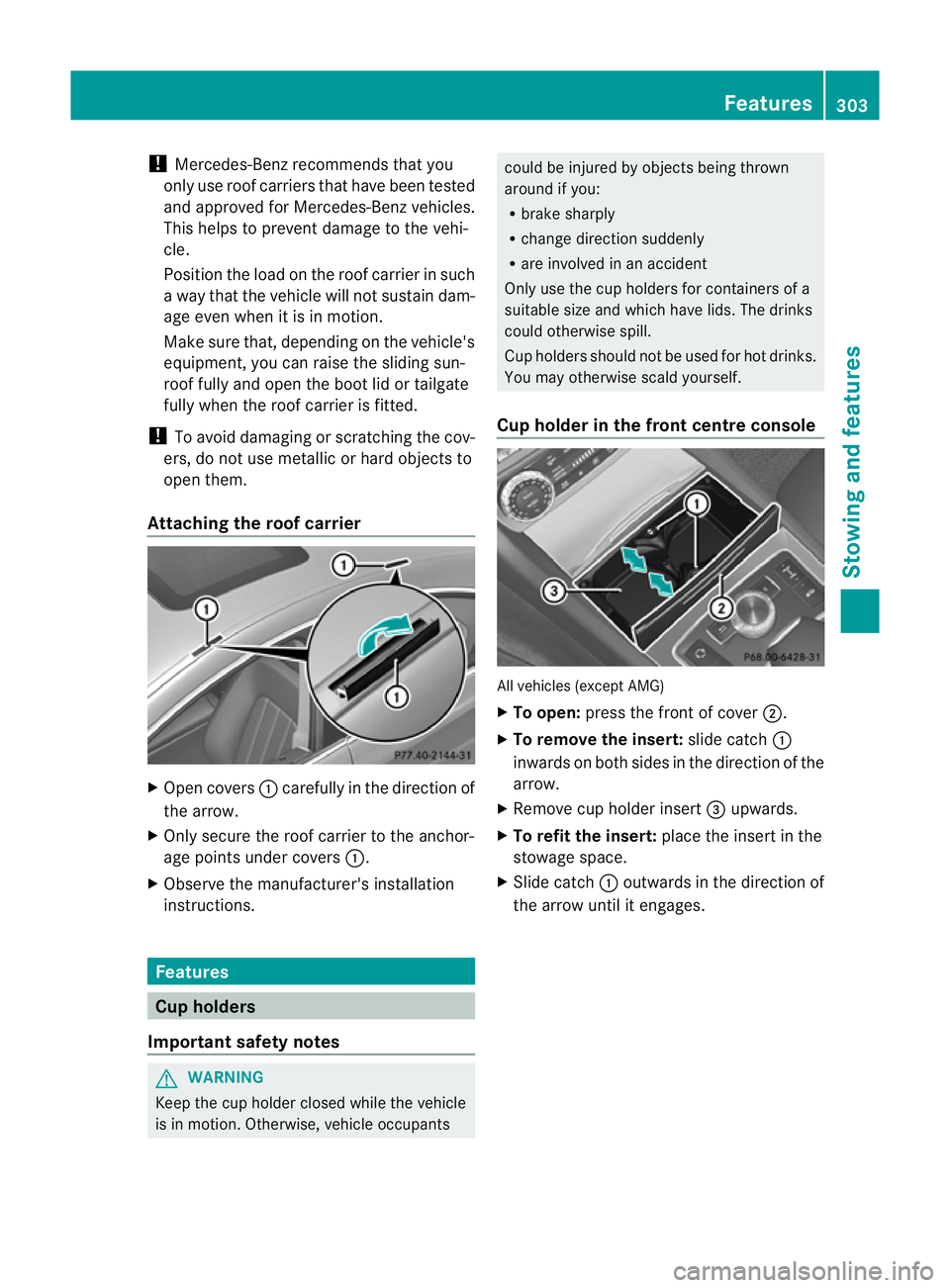
Attaching the roof carrier X
Open covers :carefully in the direction of
the arrow.
X Only secure the roof carrier to the anchor-
age points under covers :.
X Observe the manufacturer's installation
instructions. Features
Cup holders
Important safety notes G
WARNING
Keep the cup holder closed while the vehicle
is in motion. Otherwise, vehicle occupants could be injured by objects being thrown
around if you:
R
brake sharply
R change direction suddenly
R are involved in an accident
Only use the cup holders for containers of a
suitable size and which have lids. The drinks
could otherwise spill.
Cup holders should not be used for hot drinks.
You may otherwise scald yourself.
Cup holder in the front centre console All vehicles (except AMG)
X
To open: press the front of cover ;.
X To remove the insert: slide catch:
inwards on both sides in the direction of the
arrow.
X Remove cup holder insert =upwards.
X To refit the insert: place the insert in the
stowage space.
X Slide catch :outwards in the direction of
the arrow until it engages. Features
303Stowing and features Z
Page 337 of 405
Useful information
i This Owner's Manual describes all mod-
els, series and optional equipment for your
vehicle that were available at the time of
going to press. National variations are pos-
sible. Note that your vehicle may not be
equipped with all of the functions descri-
bed. This is also the case for systems and
functions relevant to safety.
i Read the information on qualified special-
ist workshops: (Y page 24). Where will I find...?
Warning triangle
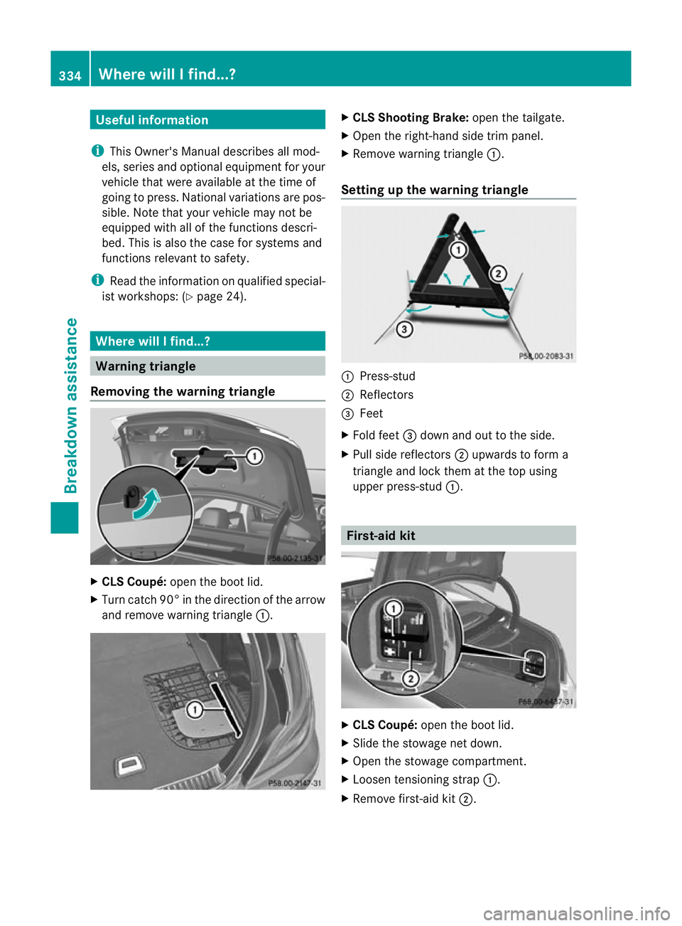
Removing the warning triangle X
CLS Coupé: open the boot lid.
X Turn catc h90° in the direction of the arrow
and remove warning triangle :. X
CLS Shooting Brake: open the tailgate.
X Open the right-hand side trim panel.
X Remove warning triangle :.
Setting up the warning triangle :
Press-stud
; Reflectors
= Feet
X Fold feet =dow nand ou tto the side.
X Pull side reflectors ;upwards to form a
triangle and lock them at the top using
upper press-stud :. First-aid kit
X
CLS Coupé: open the boot lid.
X Slide the stowage net down.
X Open the stowage compartment.
X Loosen tensioning strap :.
X Remove first-aid kit ;.334
Where will I find...?Breakdown assistance
Page 338 of 405
X
CLS Shooting Brake: open the boot lid.
X Open the stowage compartment.
X Remove first-aid kit :.
i Chec kthe expiry date on the first-aid kit
at least once a year. Replace the contents
if necessary, and replace any missing
items. Fire extinguisher
! Keep the stowage compartmentc losed
while the vehicle is in motion. It may oth-
erwise be damaged.
The fire extinguisher is located in the stowage
compartment underneath the driver's seat. X
Pull handle :upward and fold cover ;
forward.
X Remove the fire extinguisher fro mthe
stowage compartment.
i Have fire extinguisher ;refilled after
each use and checked every one to two
years. It may otherwise fail in an emer-
gency. Observe the legal requirements for each
individual country. Vehicle tool kit
General notes The vehicle tool kit can be found in the stow-
age well under the boot floor/luggage com-
partment floor. Depending on the vehicle
equipment, the vehicle tool kit is on the left-
hand side or the right-hand side in the stow-
age well under the boot floor/load compart-
ment floor.
i
Apart from certain country-specific varia-
tions, vehicles are not equipped with a tyre-
change tool kit. Some tools for changing a
wheel are specific to the vehicle. For more
information on which tools are required to
perform a wheel change on your vehicle,
consult a qualified specialist workshop.
Necessary wheel-changing tools can
include, for example:
R jack
R wheel chock
R wheel wrench
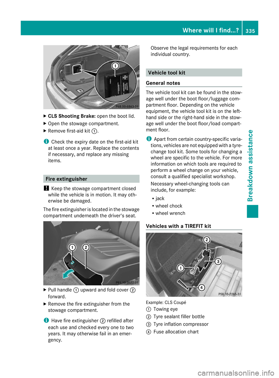
Vehicles with aTIREFIT kit Example: CLS Coupé
:
Towing eye
; Tyre sealan tfiller bottle
= Tyre inflation compressor
? Fuse allocation chart Where will I find...?
335Breakdown assistance