2012 MERCEDES-BENZ CLS SHOOTING BRAKE boot
[x] Cancel search: bootPage 168 of 405
Problem Possible causes/consequences and
M Solutions
The fuel filler flap can-
not be opened. The fuel filler flap is not unlocked.
or
The key battery is discharged.
X
Unlock the vehicle using the emergency key element
(Y page 78).
X Open the boot lid or the tailgate.
X CLS Coupé: open the boot lid.
or
X CLS Shooting Brake: open the tailgate.
X Manually unlock the fuel filler flap using the emergency release
(Y page 163). The fuel filler flap is unlocked, but the opening mechanism is jam-
med.
X
Consult a qualified specialist workshop. Parking
Important safety notes
G
WARNING
If flammable materials such as leaves, grass
or twigs are exposed to prolonged contact to
parts of the exhaust system that heat up, they
could ignite. There is a risk of fire.
Park the vehicle so that no flammable mate-
rials come into contact with parts of the vehi-
cle which are hot. Take particular care not to
park on dry grassland or harvested grain
fields. G
WARNING
If you switch off the ignition while driving,
safety-relevant functions are only available
with limitations, or not at all. This could affect,
for example, the power steering and the brake
boosting effect.Y ou will require considerably
more effort to steer and brake. There is a risk
of an accident.
Do not switch off the ignition while driving. G
WARNING
If you leave children unsupervised in the vehi-
cle, they could set it in motion by, for example:
R releasing the parking brake
R shifting the automatic transmission out of
the parking position P
R starting the engine.
They could also operate the vehicle's equip-
ment.T here is a risk of an accident and injury.
When leaving the vehicle, always take the key
with you and lock the vehicle. Never leave
children unsupervised in the vehicle.
! Am oving vehicle can lead to damage to
the vehicle or damage to the drive train.
To ensure that the vehicle is secured against
rolling away unintentionally:
R the parking brake must be applied.
R the transmission must be in position Pand
the key must be removed from the ignition
lock.
R on uphill or downhill gradients, the front
wheels must be turned towards the kerb. Parking
165Driving and parking Z
Page 201 of 405
Reversing camera
Important safety notes G
WARNING
Make sure that no persons or animals are in
the manoeuvring range. Otherwise, they
could be injured. G
WARNING
The reversing camera is only an aid and may
display obstacles in a distorted or incorrect
manner, or may not eve ndisplay the matall.
The reversing camera does not relieve you of
the responsibility to pay attention. The cam-
era cannot show objects:
R very near to the rear bumper
R below the rear bumper
R in the area immediately above the boot lid
handle/tailgate handle recess
You are always responsible for safety and
must continue to pay attention to your imme-
diate surroundings when parking and
manoeuvring. This applies to the areas
behind, in front of and nex tto the vehicle. You
could otherwise endanger yourself and oth-
ers. G
WARNING
Under the following circumstances, the
reversing camera will not function, or will
function in a limited manner:
R if the boot lid/tailgate is open
R in heavy rain, snow or fog
R at night or in very dark places
R if the camera is exposed to very bright light
R if the area is lit by fluorescent light (the dis-
play may flicker)
R if there is a sudden change in temperature,
e.g. when driving into a heated garage in
winter
R if the camera lens is dirty or obstructed
R if the rear of your vehicle is damaged. In this
event, have the camera position and setting
checked at a qualified specialist workshop. Mercedes-Benz recommends that you use
a Mercedes-Benz Service Centre for this
purpose.
Do not use the reversing camera in these
types of situation. You could otherwise injure
others or damage objects and your vehicle
while you are parking.
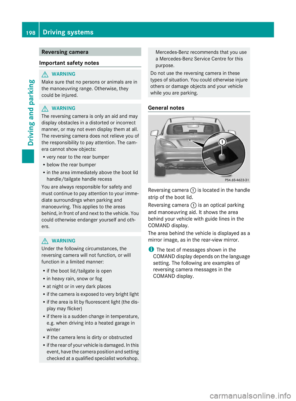
General notes Reversing camera
:is located in the handle
strip of the boot lid.
Reversing camera :is an optical parking
and manoeuvring aid. It shows the area
behind your vehicle with guide lines in the
COMAND display.
The area behind the vehicle is displayed as a
mirror image, as in the rear-view mirror.
i The text of messages shown in the
COMAND display depends on the language
setting. The following are examples of
reversing camera messages in the
COMAND display. 198
Driving systemsDriving and parking
Page 223 of 405
R
Maintain a greater distance from the vehi-
cle in front than when driving without a
trailer.
R Avoid braking abruptly. If possible, brake
gently at first to allow the trailer to run on.
Then, increase the braking force rapidly.
R The values given for gradient-climbing
capabilities from a standstill refer to sea
level. When driving in mountainous areas,
note that the power output of the engine,
and consequently the vehicle's gradient-
climbing capability, decrease with increas-
ing altitude. Folding out the ball coupling
G
WARNING
If the ball coupling is not correctly engaged,
the trailer can detach. There is a risk of an
accident.
Always engage the ball coupling as described. G
WARNING
If you release the ball coupling or it does not
engage correctly when folding in, it will swing
out. Within pivoting range of the ball coupling,
there is an increased risk of an accident and
injury.
Only release the ball coupling if the pivoting
range is unobstructed. Always make sure that
the ball coupling engages when folding in. CLS Shooting Brake
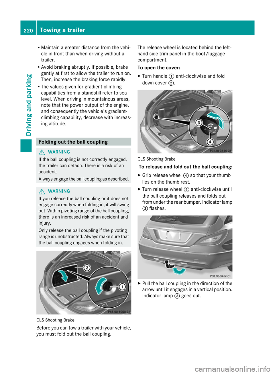
Before you can tow a trailer with your vehicle,
you must fold out the ball coupling. The release wheel is located behind the left-
hand side trim panel in the boot/luggage
compartment.
To open the cover:
X
Turn handle :anti-clockwise and fold
down cover ;. CLS Shooting Brake
To release and fold out the ball coupling:
X Grip release wheel ?so that your thumb
lies on the thumb rest.
X Turn release wheel ?anti-clockwise until
the ball coupling releases and folds out
from under the rear bumper. Indicator lamp
= flashes. X
Pull the ball coupling in the direction of the
arrow until it engages in a vertical position.
Indicator lamp =goes out. 220
Towing
atrailerDriving an d parking
Page 225 of 405
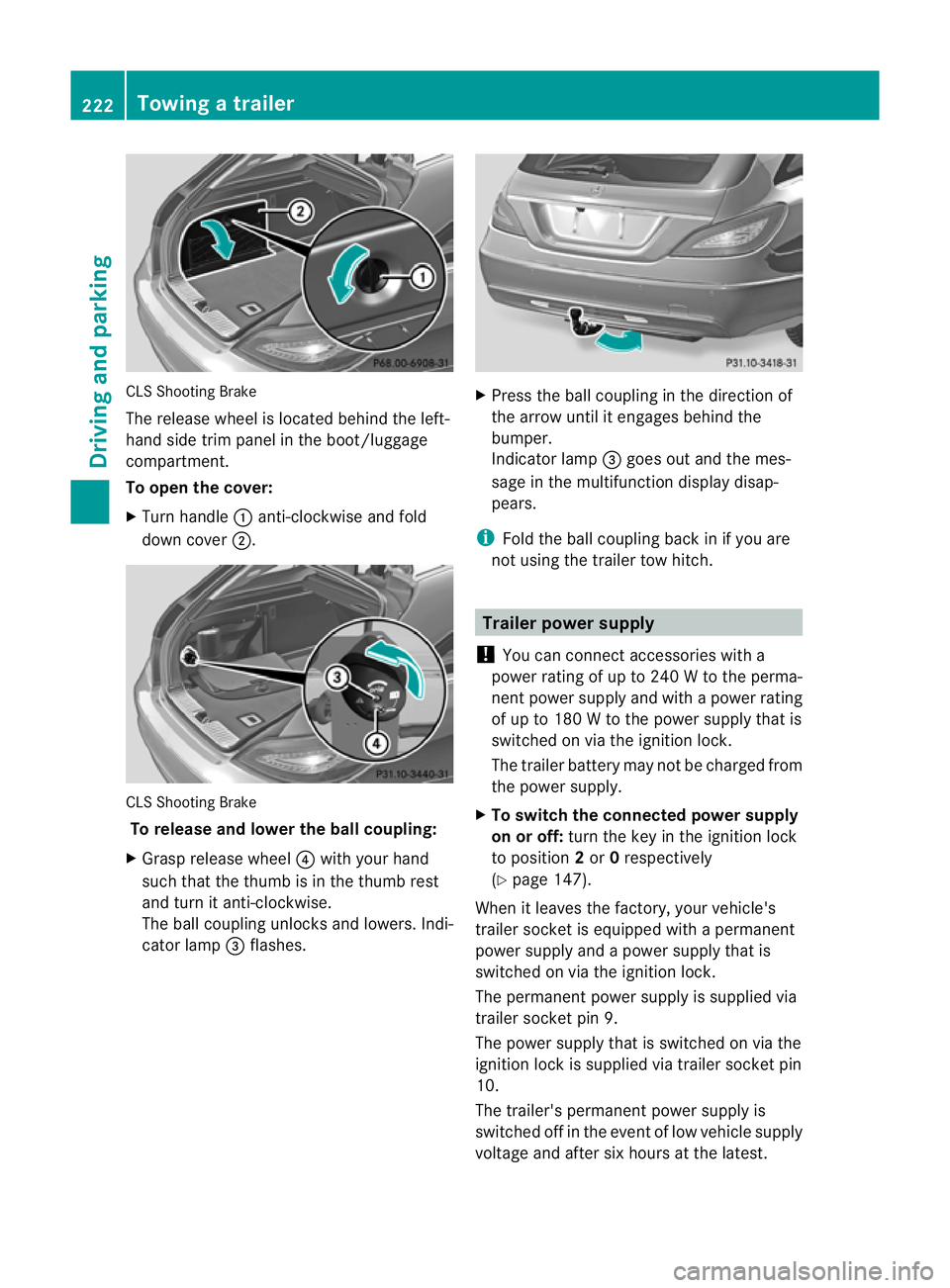
CLS Shooting Brake
The release wheel is located behind the left-
hand side trim panel in the boot/luggage
compartment.
To open the cover:
X
Turn handle :anti-clockwise and fold
down cover ;. CLS Shooting Brake
To release and lower the ball coupling:
X Grasp release wheel ?with your hand
such that the thumb is in the thumb rest
and turn it anti-clockwise.
The ball coupling unlocks and lowers. Indi-
cator lamp =flashes. X
Press the ball coupling in the direction of
the arrow until it engages behind the
bumper.
Indicator lamp =goes out and the mes-
sage in the multifunction display disap-
pears.
i Fold the ball coupling back in if you are
no tu sing the trailer tow hitch. Trailer power supply
! You can connect accessories with a
power rating of up to 240 W to the perma-
nent power supply and with a power rating
of up to 180 W to the power supply that is
switched on via the ignition lock.
The trailer battery may not be charged from
the power supply.
X To switch the connected power supply
on or off: turn the key in the ignition lock
to position 2or 0respectively
(Y page 147).
When it leaves the factory, your vehicle's
trailer socket is equipped with a permanent
power supply and a power supply that is
switched on via the ignition lock.
The permanent power supply is supplied via
trailer socket pin 9.
The power supply that is switched on via the
ignition lock is supplied via trailer socket pin
10.
The trailer's permanent power supply is
switched off in the event of low vehicle supply
voltage and after six hours at the latest. 222
Towing
atrailerDriving an d parking
Page 245 of 405
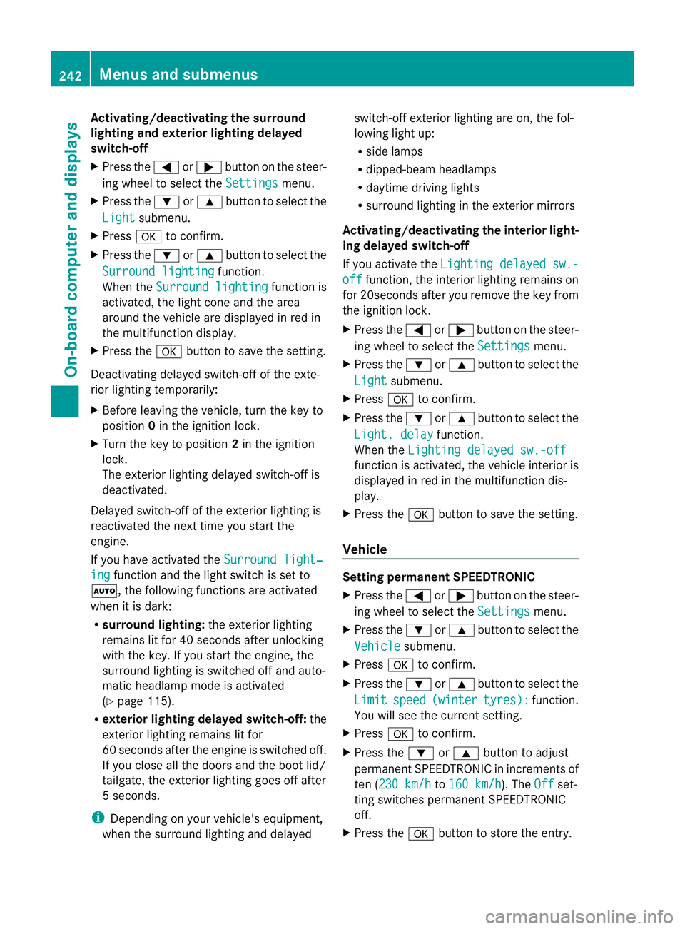
Activating/deactivating the surround
lighting and exterior lightin
gdelayed
switch-off
X Press the =or; button on the steer-
ing wheel to selec tthe Settings menu.
X Press the :or9 button to select the
Light submenu.
X Press ato confirm.
X Press the :or9 button to select the
Surround lighting function.
When the Surround lighting function is
activated, the light cone and the area
around the vehicle are displayed in red in
the multifunction display.
X Press the abutton to save the setting.
Deactivating delayed switch-off of the exte-
rior lighting temporarily:
X Before leaving the vehicle, turn the key to
position 0in the ignition lock.
X Turn the key to position 2in the ignition
lock.
The exterior lighting delayed switch-off is
deactivated.
Delayed switch-off of the exterior lighting is
reactivated the next time you start the
engine.
If you have activated the Surround light‐ing function and the light switch is set to
Ã, the following functions are activated
when it is dark:
R surround lighting: the exterior lighting
remains lit for 40 seconds after unlocking
with the key. If you start the engine, the
surround lighting is switched off and auto-
matic headlamp mode is activated
(Y page 115).
R exterior lighting delayed switch-off: the
exterior lighting remains lit for
60 seconds after the engine is switched off.
If you close all the doors and the boot lid/
tailgate, the exterior lighting goes off after
5s econds.
i Depending on your vehicle's equipment,
when the surround lighting and delayed switch-off exterior lighting are on, the fol-
lowing light up:
R
side lamps
R dipped-beam headlamps
R daytime driving lights
R surround lighting in the exterior mirrors
Activating/deactivating the interior light-
ing delayed switch-off
If you activate the Lighting delayed sw.- off function, the interior lighting remains on
for 20seconds after you remove the key from
the ignition lock.
X Press the =or; button on the steer-
ing wheel to select the Settings menu.
X Press the :or9 button to select the
Light submenu.
X Press ato confirm.
X Press the :or9 button to select the
Light. delay function.
When the Lighting delayed sw.-off function is activated, the vehicle interior is
displayed in red in the multifunction dis-
play.
X Press the abutton to save the setting.
Vehicle Setting permanent SPEEDTRONIC
X
Press the =or; button on the steer-
ing wheel to select the Settings menu.
X Press the :or9 button to select the
Vehicle submenu.
X Press ato confirm.
X Press the :or9 button to select the
Limit speed (winter tyres): function.
You will see the curren tsetting.
X Press ato confirm.
X Press the :or9 button to adjust
permanent SPEEDTRONIC in increment sof
ten ( 230 km/h to
160 km/h ). The
Off set-
ting switches permanent SPEEDTRONIC
off.
X Press the abutton to store the entry. 242
Menus and submenusOn-board computer and displays
Page 275 of 405
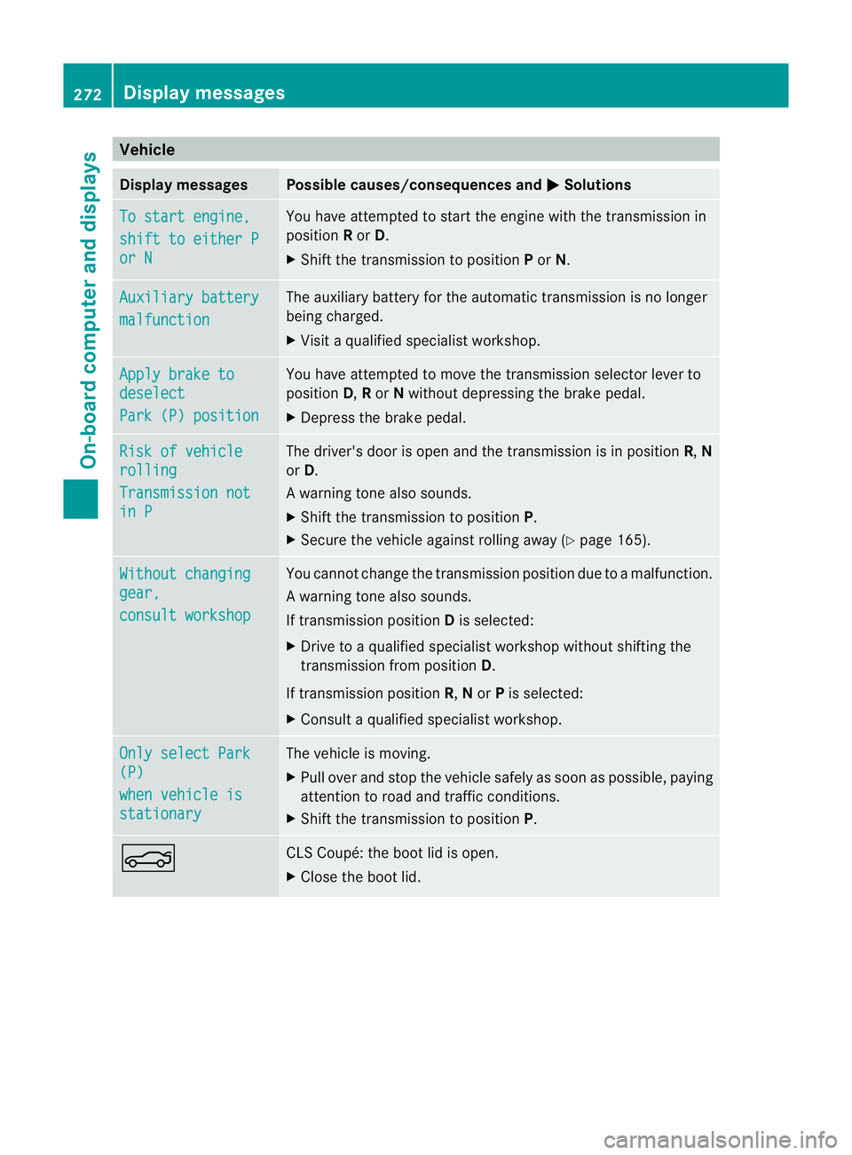
Vehicle
Display messages Possible causes/consequences and
M Solutions
To start engine,
shift to either P
or N You have attempted to start the engine with the transmission in
position
Ror D.
X Shift the transmission to position Por N. Auxiliary battery
malfunction The auxiliary battery for the automatic transmission is no longer
being charged.
X
Visit a qualified specialist workshop. Apply brake to
deselect
Park (P) position You have attempted to move the transmission selector lever to
position
D,Ror Nwithou tdepressing the brake pedal.
X Depress the brake pedal. Risk of vehicle
rolling
Transmission not
in P The driver's door is open and the transmission is in position
R,N
or D.
Aw arning tone also sounds.
X Shift the transmission to position P.
X Secure the vehicle against rolling away ( Ypage 165). Without changing
gear,
consult workshop You canno
tchange the transmission position due to a malfunction.
Aw arning tone also sounds.
If transmission position Dis selected:
X Drive to a qualified specialist workshop without shifting the
transmission from position D.
If transmission position R,Nor Pis selected:
X Consult a qualified specialist workshop. Only select Park
(P)
when vehicle is
stationary The vehicle is moving.
X
Pull ove rand stop the vehicle safely as soo nas possible, paying
attention to road and traffic conditions.
X Shift the transmission to position P.N CLS Coupé: the boot lid is open.
X
Close the boot lid. 272
Display messagesOn-board computer and displays
Page 293 of 405
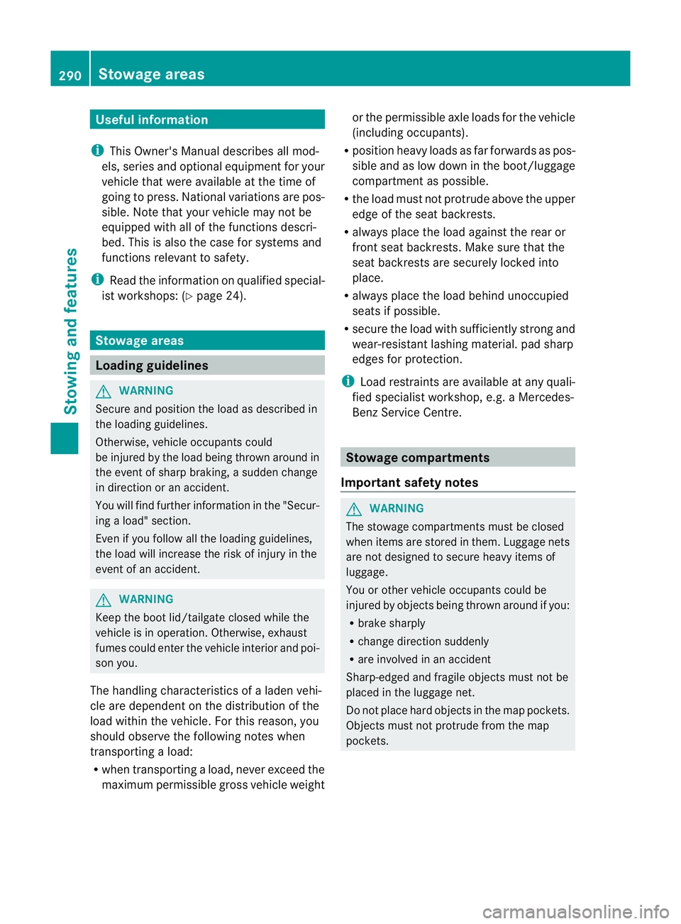
Useful information
i This Owner's Manual describes all mod-
els, series and optional equipment for your
vehicle that were available at the time of
going to press. National variations are pos-
sible. Note that your vehicle may not be
equipped with all of the functions descri-
bed. This is also the case for systems and
functions relevant to safety.
i Read the information on qualified special-
ist workshops: (Y page 24). Stowage areas
Loading guidelines
G
WARNING
Secure and position the load as described in
the loading guidelines.
Otherwise, vehicle occupants could
be injured by the load being thrown around in
the even tofsharp braking, a sudden change
in direction or an accident.
You will find further information in the "Secur-
ing a load" section.
Even if you follow all the loading guidelines,
the load will increase the risk of injury in the
event of an accident. G
WARNING
Keep the boot lid/tailgate closed while the
vehicle is in operation. Otherwise, exhaust
fumes could enter the vehicle interior and poi-
son you.
The handling characteristics of a laden vehi-
cle are dependent on the distribution of the
load within the vehicle. For this reason, you
should observe the following notes when
transporting a load:
R when transporting a load, never exceed the
maximum permissible gross vehicle weight or the permissible axle loads for the vehicle
(including occupants).
R position heavy loads as far forwards as pos-
sible and as low down in the boot/luggage
compartmenta s possible.
R the load must not protrude above the upper
edge of the seat backrests.
R always place the load against the rear or
front seat backrests. Make sure that the
seat backrests are securely locked into
place.
R always place the load behind unoccupied
seats if possible.
R secure the load with sufficiently strong and
wear-resistant lashing material. pad sharp
edges for protection.
i Load restraints are available at any quali-
fied specialist workshop, e.g. a Mercedes-
Benz Service Centre. Stowage compartments
Important safety notes G
WARNING
The stowage compartments must be closed
when items are stored in them. Luggage nets
are not designed to secure heavy items of
luggage.
You or other vehicle occupants could be
injured by objects being thrown around if you:
R brake sharply
R change direction suddenly
R are involved in an accident
Sharp-edged and fragile objects must not be
placed in the luggage net.
Do not place hard objects in the map pockets.
Objects must not protrude from the map
pockets. 290
Stowage areasStowing and features
Page 296 of 405
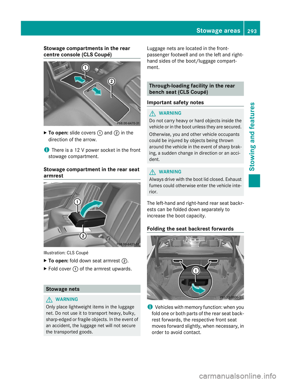
Stowage compartments in the rear
centre console (CLS Coupé)
X
To open: slide covers :and ;in the
direction of the arrow.
i There is a 12 V power socket in the front
stowage compartment.
Stowage compartment in the rear seat
armrest Illustration: CLS Coupé
X
To open: fold down seat armrest ;.
X Fold cover :of the armrest upwards. Stowage nets
G
WARNING
Only place lightweight items in the luggage
net. Do not use it to transport heavy, bulky,
sharp-edged or fragile objects. In the event of
an accident, the luggage net will not secure
the transported goods. Luggage nets are located in the front-
passenger footwell and on the left and right-
hand sides of the boot/luggage compart-
ment. Through-loading facility in the rear
bench seat (CLS Coupé)
Important safety notes G
WARNING
Do not carry heavy or hard objects inside the
vehicle or in the boot unless they are secured.
Otherwise, you and other vehicle occupants
could be injured by objectsb eing thrown
around the vehicle in the event of sharp brak-
ing, a sudden change in direction or an acci-
dent. G
WARNING
Always drive with the boot lid closed. Exhaust
fumes could otherwise enter the vehicle inte-
rior.
The left-hand and right-hand rear seat backr-
ests can be folded down separately to
increase the boot capacity.
Folding the seat backrest forwards i
Vehicles with memory function :when you
fold one or both parts of the rear seat back-
rest forwards, the respective front seat
moves forward slightly, when necessary, in
order to avoid contact. Stowage areas
293Stowing and features Z