2012 MERCEDES-BENZ CLS SHOOTING BRAKE boot
[x] Cancel search: bootPage 339 of 405
X
Open the boot lid/tailgate.
X Swing the boot floor/luggage compart-
ment floor upwards (Y page 301) or
(Y page 302).
Vehicles with a"Minispare" emergency
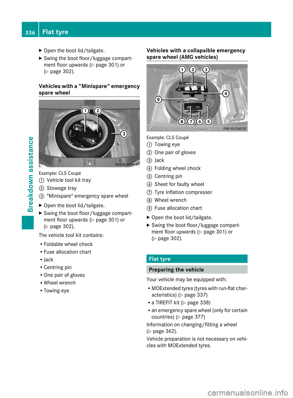
spare wheel Example
:CLS Coupé
: Vehicle tool kit tray
; Stowage tray
= "Minispare" emergency spare wheel
X Open the boot lid/tailgate.
X Swing the boot floor/luggage compart-
ment floor upwards (Y page 301) or
(Y page 302).
The vehicle tool kit contains:
R Foldable wheel chock
R Fuse allocation chart
R Jack
R Centring pin
R One pairofg loves
R Wheel wrench
R Towing eye Vehicles with
acollapsible emergency
spare wheel (AMG vehicles) Example: CLS Coupé
:
Towing eye
; One pair of gloves
= Jack
? Folding wheel chock
A Centring pin
B Sheet for faulty wheel
C Tyre inflatio ncompressor
D Wheel wrench
E Fuse allocation chart
X Open the boot lid/tailgate.
X Swing the boot floor/luggage compart-
ment floor upwards (Y page 301) or
(Y page 302). Flat tyre
Preparing the vehicle
Your vehicle may be equipped with:
R MOExtended tyres (tyres with run-flat char-
acteristics) (Y page 337)
R a TIREFIT kit (Y page 338)
R an emergency spare wheel (only for certain
countries) (Y page 377)
Information on changing/fitting a wheel
(Y page 362).
Vehicle preparation is not necessary on vehi-
cles with MOExtended tyres. 336
Flat tyreBreakdown assistance
Page 341 of 405
"MOExtended". Make sure that you only
use the size of tyre specified for the vehicle.
TIREFIT kit
Using the TIREFIT kit TIREFIT is a tyre sealant.
You can use TIREFIT to seal punctures of up
to 4 mm, particularly those in the tyre tread.
You can use TIREFIT at outside temperatures
down to Ò20 †. G
WARNING
In the following situations, the tyre sealan tis
unable to provide sufficient breakdown assis-
tance, as it is unable to seal the tyre properly:
R there are cuts or punctures in the tyre
larger than those mentione dabove.
R the wheel rim is damaged.
R you have driven at very low tyre pressures
or on a flat tyre.
There is a risk of accident.
Do not drive any further. Contact a qualified
specialist workshop. G
WARNING
The tyre sealant is harmful and causes irrita-
tion. It must not come into contact with your
skin, eyes or clothing or be swallowed. Do not
inhale TIREFIT fumes. Keep tyre sealant away
from children. There is a risk of injury.
If you come into contact with the tyre sealant,
observe the following:
R Rinse off the tyre sealant from your skin
immediately with water.
R If the tyre sealant comes into contact with
your eyes, immediately rinse them thor-
oughly with clean water.
R If tyre sealant is swallowed, immediately
rinse your mouth out thoroughly and drink
plenty of water. Do not induce vomiting,
and seek medical attention immediately. R
Immediately change out of clothing which
has come into contact with tyre sealant.
R If an allergic reaction occurs, seek medical
attention immediately.
! Do not operate the tyre inflation com-
pressor for longer than eight minutes at a
time without a break. It may otherwise
overheat.
The tyre inflation compressor can be oper-
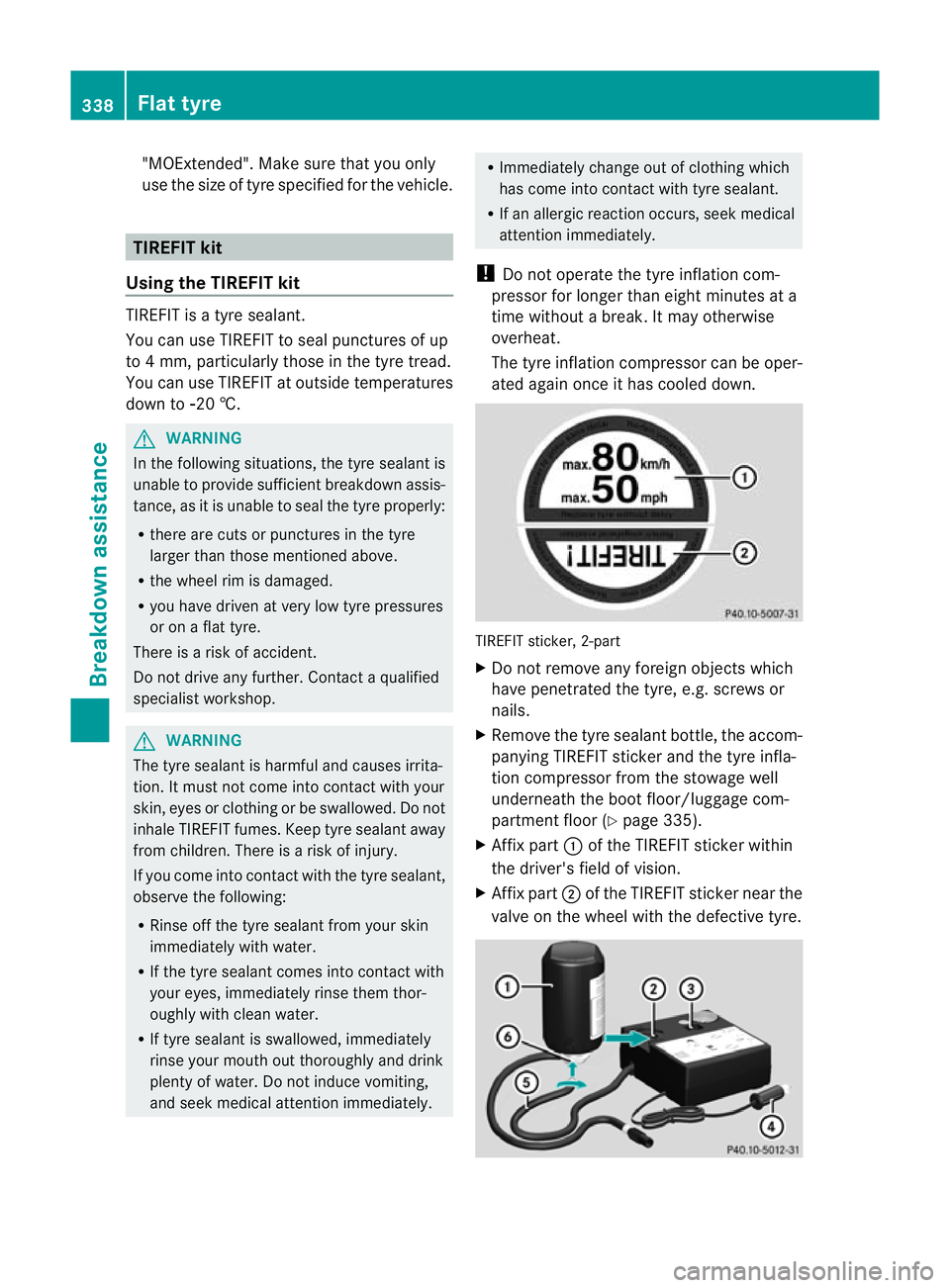
ated again once it has cooled down. TIREFIT sticker, 2-part
X
Do not remove any foreign objects which
have penetrated the tyre, e.g. screws or
nails.
X Remove the tyre sealant bottle, the accom-
panying TIREFIT sticker and the tyre infla-
tion compressor from the stowage well
underneath the boot floor/luggage com-
partment floor (Y page 335).
X Affix part :of the TIREFIT sticker within
the driver's field of vision.
X Affix part ;of the TIREFIT sticker near the
valve on the wheel with the defective tyre. 338
Flat tyreBreakdown assistance
Page 353 of 405
Electrical fuses
Important safety notes
G
WARNING
Only use fuses that have been approved for
Mercedes-Ben zvehicles and which have the
correct fuse rating for the systems con-
cerned. Do not attempt to repair or bridge
faulty fuses. Using fuses which have not been
approved or attempting to repair or bridge
faulty fuses could cause the fuse to be over-
loaded and result in a fire. Have the cause
traced and rectified at a qualified specialist
workshop.
! Only use fuses that have been approved
for Mercedes-Benz vehicles and which
have the correct fuse rating for the system
concerned. Otherwise, components or sys-
tems could be damaged.
The fuses in your vehicle serve to close down
faulty circuits. If afuse blows, all the compo-
nents on the circuit and their functions stop
operating.
Blown fuses must be replace dwith fuses of
the same rating, which you can recognise by
the colour and fuse rating. The fuse ratings
are listed in the fuse allocation chart.
If the newly inserted fuse also blows, have the
cause traced and rectified at a qualified spe-
cialist workshop, e.g. a Mercedes-Benz
Service Centre. Before replacing a fuse
X Secure the vehicle against rolling away
(Y page 165).
X Switch off all electrical consumers.
X Turn the key to position 0in the ignition
lock and remove it (Y page 147).
or
X On vehicles with KEYLESS-GO, make sure
the ignition is switched off (Y page 147).
All indicator lamps in the instrumen tcluster
must be off. The fuses are located in various fuse boxes:
R
fuse box in the engine compartmen tonthe
left-hand side of the vehicle, when viewed
in the direction of travel
R CLS Coupé: fuse box in the boot on the
right-hand side of the vehicle, when viewed
in the direction of travel
R CLS Shooting Brake: fuse box in the lug-
gage compartmentont he right-hand side
of the vehicle, when viewed in the direction
of travel
CLS Coupé: the fuse allocation chart is loca-
ted in the vehicle tool kit in the stowage com-
partment under the boot floor (Y page 335).
CLS Shooting Brake: the fuse allocation
chart is located in the vehicle tool kit in the
stowage compartmentu nderthe luggage
compartment floor (Y page 335). Fuse box in the engine compartment
G
WARNING
Make sure that the windscreen wipers are
turned off and the key is pulled out of the igni-
tion lock before you open the cover of the fuse
box. Otherwise, the windscreen wipers and
the wiper rods above the cover could be set
in motion. This could lead to you or others
being injured by the wiper rods.
! Make sure that no moisture can enter the
fuse box when the cover is open.
! When closing the cover, make sure that it
is lying correctly on the fuse box. Moisture
seeping in or dirt could otherwise impair
the operation of the fuses.
X Make sure that the windscreen wipers are
switched off.
X Open the bonnet. 350
Electrical fusesBreakdown assistance
Page 354 of 405
X
Remove any existing moisture from the
fuse box using a dry cloth.
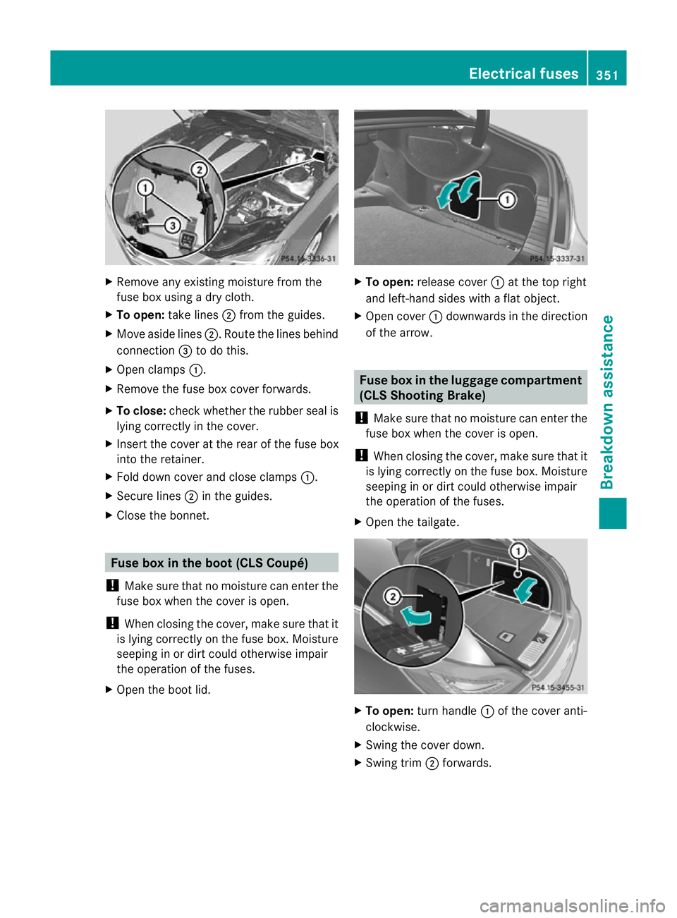
X To open: take lines ;from the guides.
X Move aside lines ;.Route the lines behind
connection =to do this.
X Open clamps :.
X Remove the fuse box cover forwards.
X To close: check whether the rubber seal is
lying correctly in the cover.
X Insert the cover at the rear of the fuse box
into the retainer.
X Fold down cover and close clamps :.
X Secure lines ;in the guides.
X Close the bonnet. Fuse box in the boot (CLS Coupé)
! Make sure that no moisture can enter the
fuse box when the cover is open.
! When closing the cover, make sure that it
is lying correctly on the fuse box. Moisture
seeping in or dirt could otherwise impair
the operation of the fuses.
X Open the boot lid. X
To open: release cover :at the top right
and left-hand sides with a flat object.
X Open cover :downwards in the direction
of the arrow. Fuse box in the luggage compartment
(CLS Shooting Brake)
! Make sure that no moisture can enter the
fuse box when the cover is open.
! When closing the cover, make sure that it
is lying correctly on the fuse box. Moisture
seeping in or dirt could otherwise impair
the operation of the fuses.
X Open the tailgate. X
To open: turn handle :of the cover anti-
clockwise.
X Swing the cover down.
X Swing trim ;forwards. Electrical fuses
351Breakdown assistance Z
Page 367 of 405
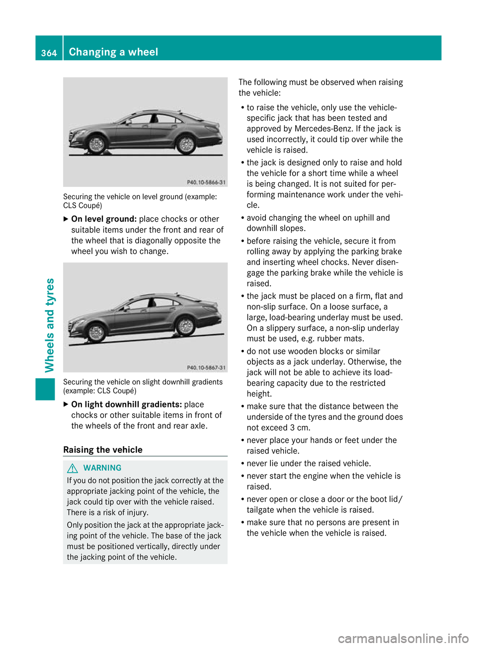
Securing the vehicle on level ground (example:
CLS Coupé)
X
On level ground: place chocks or other
suitable items under the front and rea rof
the wheel tha tis diagonally opposite the
wheel you wish to change. Securing the vehicle on slight downhill gradients
(example: CLS Coupé)
X On light downhill gradients: place
chocks or other suitable items in front of
the wheels of the front and rear axle.
Raising the vehicle G
WARNING
If you do not position the jack correctly at the
appropriate jacking point of the vehicle, the
jack could tip over with the vehicle raised.
There is a risk of injury.
Only position the jack at the appropriate jack-
ing point of the vehicle. The base of the jack
must be positioned vertically, directly under
the jacking point of the vehicle. The following must be observed when raising
the vehicle:
R
to raise the vehicle, only use the vehicle-
specific jack that has been tested and
approved by Mercedes-Benz. If the jack is
used incorrectly, it could tip over while the
vehicle is raised.
R the jack is designed only to raise and hold
the vehicle for a short time while a wheel
is being changed. It is not suited for per-
forming maintenance work under the vehi-
cle.
R avoid changing the wheel on uphill and
downhill slopes.
R before raising the vehicle, secure it from
rolling away by applying the parking brake
and inserting wheel chocks. Never disen-
gage the parking brake while the vehicle is
raised.
R the jack must be placed on a firm, flat and
non-slip surface. On a loose surface, a
large, load-bearing underlay must be used.
On a slippery surface, a non-slip underlay
must be used, e.g. rubber mats.
R do not use wooden blocks or similar
objects as a jack underlay.O therwise, the
jac kw ill not be able to achieve its load-
bearing capacity due to the restricted
height.
R make sure that the distance between the
underside of the tyres and the ground does
not exceed 3 cm.
R never place your hands or feet under the
raised vehicle.
R never lie under the raised vehicle.
R never start the engine when the vehicle is
raised.
R never open or close a door or the boot lid/
tailgate when the vehicle is raised.
R make sure that no persons are present in
the vehicle when the vehicle is raised. 364
Changing
awheelWheels and tyres
Page 370 of 405

Tightening wheel bolts (example: vehicle with
emergency spare wheel)
X Turn the crank of the jack anti-clockwise
until the vehicle is once again standing
firmly on the ground.
X Place the jack to one side.
X Tighten the wheel bolts evenly in a cross-
wise pattern in the sequence indicated
(: toA). The tightening torque must be
130 Nm.
X Turn the jack back to its initial position.
X Stow the jack and the rest of the vehicle
tools in the boot again.
X Check the air pressure of the newly fitted
wheel and adjust accordingly.
Observe the recommended tyre pressure
(Y page 357).
i Vehicles with tire pressure control sys-
tem: all fitted wheels must be equipped
with functioning sensors. Wheel and tyre combinations
General notes
! For safety reasons, Mercedes-Benz rec-
ommends that you only use tyres and
wheels which have been approved by
Mercedes-Benz specifically for your vehi-
cle. These are specially adapted to the control
systems, such as ABS or ESP
®
and are
marked as follows:
R MO =Mercedes-BenzO riginal
R MOE =Mercedes-BenzO riginal Extended
(tyres featuring run-flat characteristics)
R MO1 =Mercedes-BenzO riginal (only cer-
tain AMG tyres)
Mercedes-Benz Original Extended tyres
may only be used on wheels that have been
specifically approved by Mercedes-Benz.
Only use tyres, wheels or accessories tes-
ted and approved by Mercedes-Benz. Cer-
tain characteristics, e.g. handling, vehicle
noise emissions or fuel consumption, may
otherwise be adversely affected. In addi-
tion, when driving with aload, tyre dimen-
sion variations could cause the tyres to
come into contact with the bodywork and
axle components.T his could result in dam-
age to the tyres or the vehicle.
Mercedes-Ben zaccepts no liability for
damage resulting from the use of tyres,
wheels or accessories othe rthan those tes-
ted and approved.
Further information about wheels, tyres
and approved combinations can be
obtained from any qualified specialist
workshop.
! Retreaded tyres are neither tested nor
recommended by Mercedes-Benz, since
previous damage cannot always be detec-
ted on retreaded tyres. As a result,
Mercedes-Ben zcannot guarantee vehicle
safety if retreaded tyres are fitted. Do not
fit used tyres if you have no information
about their previous usage.
! Large wheels :the lower the section width
for a certain wheel size, the lower the ride
comfort is on poor road surfaces. Roll com-
fort and suspension comfort are reduced
and the risk of damage to the wheels and
tyres as a result of driving over obstacles
increases. Wheel and tyre combinations
367Wheels and tyres Z
Page 380 of 405
Emergency spare wheel
Important safety notes
G
WARNING
The wheel/tyre dimensions and the tyre type
of the spare wheel/emergency spare wheel
and the wheel to be replaced may differ. Fit-
ting a spare wheel/emergency spare wheel
may severely impair the driving characteris-
tics. There is a risk of accident.
To prevent hazardous situations:
R Adap tyour driving style accordingly and
drive carefully.
R Never fit more than one spare wheel/emer-
gency spare wheel if the dimesions are dif-
ferent to those of the wheel being replaced.
R Only use a spare wheel/emergency spare
wheel briefly if the dimesions are different
to those of the wheel being replaced.
R Do not switch off ESP ®
.
R Have the spare wheel/emergency spare
wheel in question replaced at the nearest
qualified specialist workshop. Make sure
that the wheel/tyre dimensions and tyre
type are correct.
When using an emergency spare wheel or
spare wheel of a different size, you must not
exceed the maximum speed of 80 km/h.
Snow chains must not be fitted to emergency
spare wheels. General notes
You should regularly check the pressure of all
your tyres, including the emergency spare
wheel, particularly prior to long trips, and cor-
rect the pressure as necessary (Y page 357).
The applicable value is found on the wheel or
under "Technical data" (Y page 380).
An emergency spare wheel may also be fitted
against the direction of rotation .Observe the
time restriction on use as well as the speed
limitation specified on the emergency spare
wheel. Replace the tyres after six years at the latest,
regardless of wear. This also applies to the
emergency spare wheel.
i
When you are driving with the collapsible
emergency spare wheel fitted, the tyre
pressure loss warning system or the tyre
pressure monitor cannot function reliably.
Only restart the tyre pressure loss warning
system/tyre pressure monitor when the
defective wheel has been replaced with a
new wheel.
Vehicles with tyre pressure monitor:
after mounting an emergency spare wheel,
the system may still display the tyre pres-
sure of the removed wheel for a few
minutes. The value displayed for the moun-
ted emergency spare wheel is not the same
as the current tyre pressure of the emer-
gency spare wheel. Removing the "Minispare" emer-
gency spare wheel/collapsible emer-
gency spare wheel
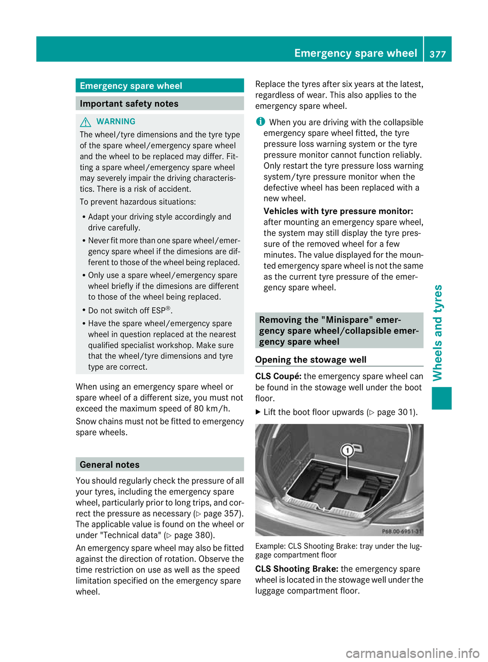
Opening the stowage well CLS Coupé:
the emergency spare wheel can
be found in the stowage well under the boot
floor.
X Lift the boot floor upwards (Y page 301). Example: CLS Shooting Brake: tray under the lug-
gage compartment floor
CLS Shooting Brake:
the emergency spare
wheel is located in the stowage well under the
luggage compartment floor. Emergency spare wheel
377Wheels and tyres Z
Page 381 of 405
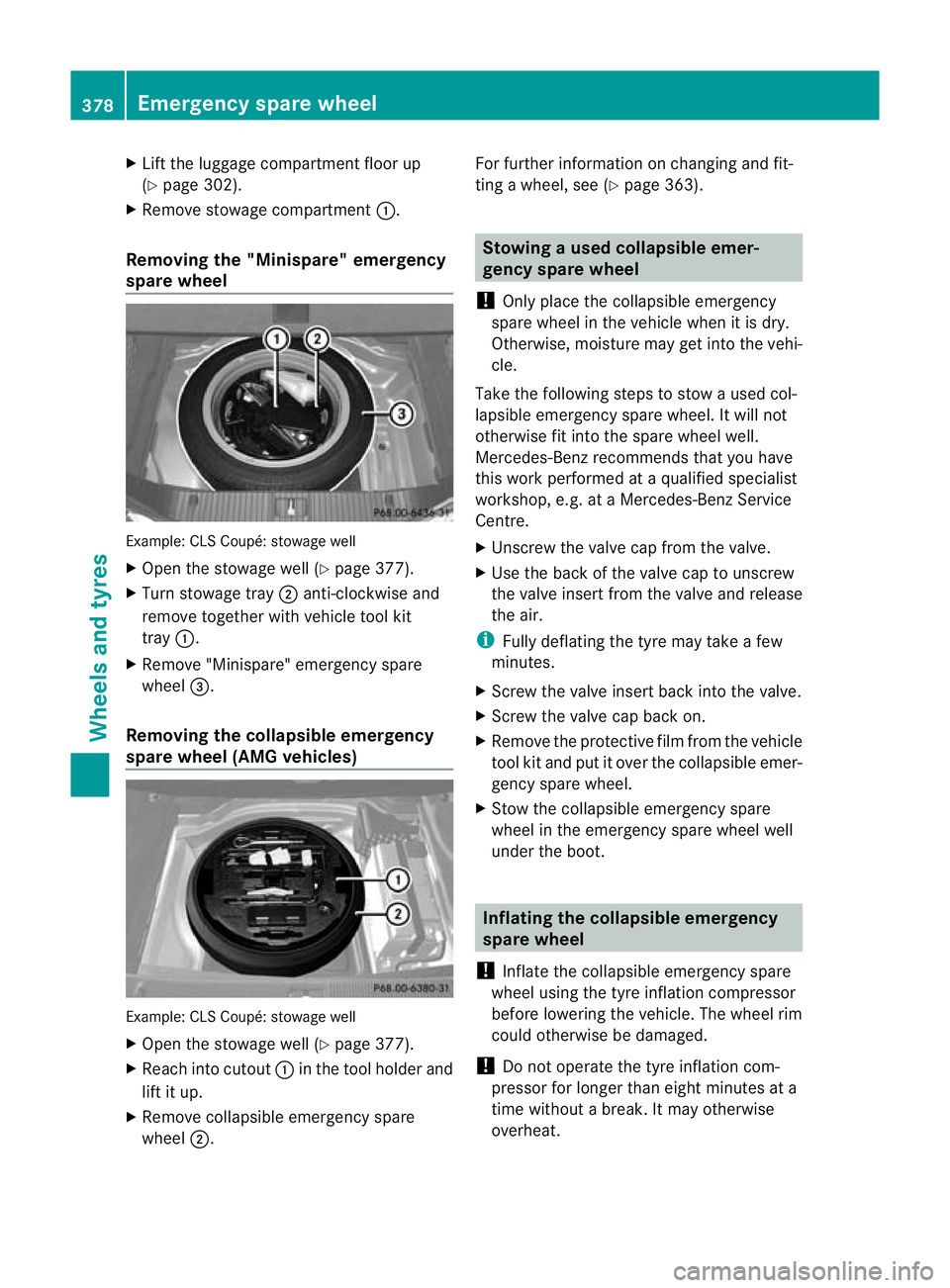
X
Lift the luggage compartment floor up
(Y page 302).
X Remove stowage compartment :.
Removing the "Minispare" emergency
spare wheel Example: CLS Coupé: stowage well
X Open the stowage well (Y page 377).
X Turn stowage tray ;anti-clockwise and
remove together with vehicle tool kit
tray :.
X Remove "Minispare" emergency spare
wheel =.
Removing the collapsible emergency
spare wheel (AMG vehicles) Example: CLS Coupé: stowage well
X Open the stowage well (Y page 377).
X Reach into cutout :in the tool holdera nd
lift it up.
X Remove collapsible emergency spare
wheel ;. For further information on changing and fit-
ting a wheel, see (Y
page 363). Stowing
aused collapsible emer-
gency spare wheel
! Only place the collapsible emergency
spare wheel in the vehicle when it is dry.
Otherwise, moisture may get into the vehi-
cle.
Take the following steps to stow a used col-
lapsible emergency spare wheel. It will not
otherwise fit into the spare wheel well.
Mercedes-Benz recommends that you have
this work performed at aqualified specialist
workshop, e.g. at a Mercedes-Ben zService
Centre.
X Unscrew the valve cap from the valve.
X Use the back of the valve cap to unscrew
the valve insert from the valve and release
the air.
i Fully deflating the tyre may take a few
minutes.
X Screw the valve insert back into the valve.
X Screw the valve cap back on.
X Remove the protective film from the vehicle
tool kit and put it over the collapsible emer-
gency spare wheel.
X Stow the collapsible emergency spare
wheel in the emergency spare wheel well
under the boot. Inflating the collapsible emergency
spare wheel
! Inflate the collapsible emergency spare
wheel using the tyre inflation compressor
before lowering the vehicle. The wheel rim
could otherwise be damaged.
! Do not operate the tyre inflation com-
pressor for longer than eight minutes at a
time without a break. It may otherwise
overheat. 378
Emergency spare wheelWheels and tyres