2012 Lancia Voyager sensor
[x] Cancel search: sensorPage 84 of 344

BLIND SPOT
MONITORING (for
versions/markets, where
provided)
The Blind Spot Monitoring (BSM)
system uses two radar-based sensors,
located inside the rear bumper fascia,
to detect highway licensable vehicles
(automobiles, trucks, motorcycles,
etc.) that enter the blind spot zones
from the rear/front/side of the ve-
hicle.
When the vehicle is started, the BSM
warning light will momentarily illu-
minate in both outside rear view mir-
rors to let the driver know that the
system is operational. The BSM sys-
tem sensors operate when the vehicle
is in any forward gear or REVERSEand enters stand-by mode when the
vehicle is in PARK.
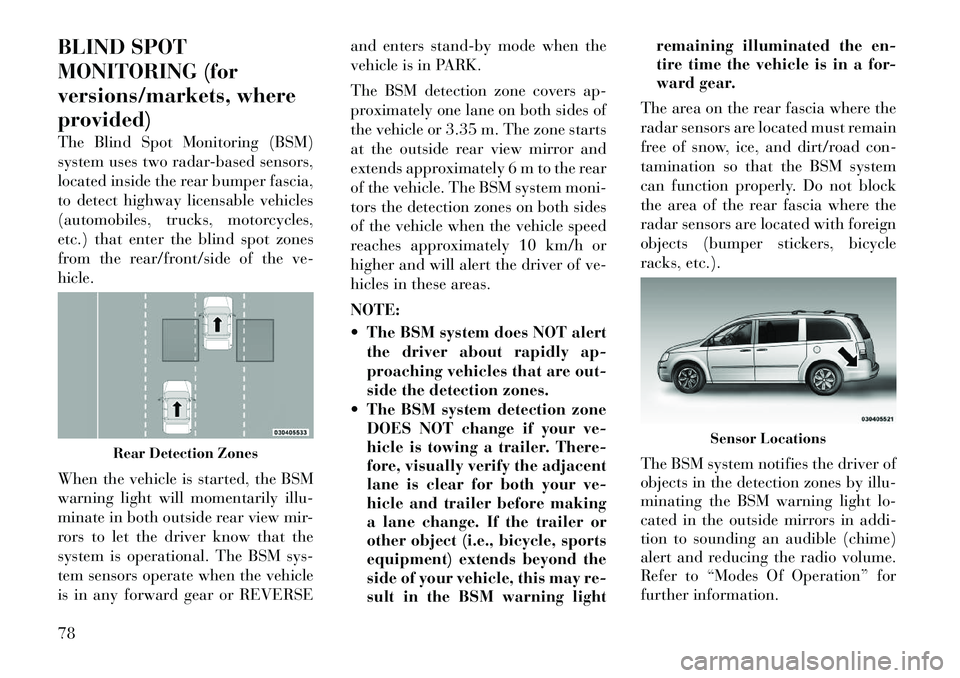
The BSM detection zone covers ap-
proximately one lane on both sides of
the vehicle or 3.35 m. The zone starts
at the outside rear view mirror and
extends approximately 6 m to the rear
of the vehicle. The BSM system moni-
tors the detection zones on both sides
of the vehicle when the vehicle speed
reaches approximately 10 km/h or
higher and will alert the driver of ve-
hicles in these areas.
NOTE:
The BSM system does NOT alert
the driver about rapidly ap-
proaching vehicles that are out-
side the detection zones.
The BSM system detection zone DOES NOT change if your ve-
hicle is towing a trailer. There-
fore, visually verify the adjacent
lane is clear for both your ve-
hicle and trailer before making
a lane change. If the trailer or
other object (i.e., bicycle, sports
equipment) extends beyond the
side of your vehicle, this may re-
sult in the BSM warning light remaining illuminated the en-
tire time the vehicle is in a for-
ward gear.
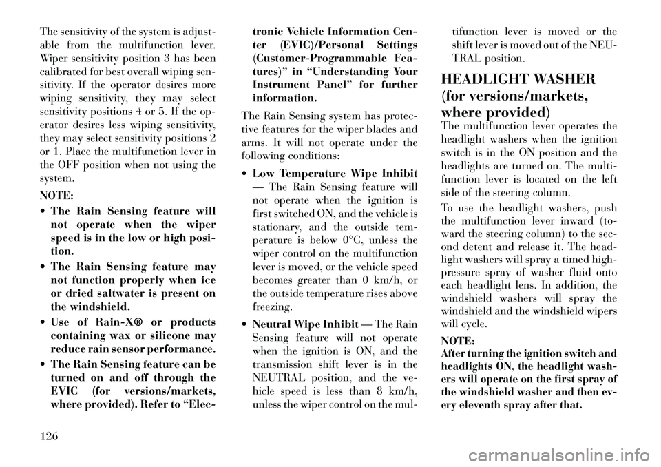
The area on the rear fascia where the
radar sensors are located must remain
free of snow, ice, and dirt/road con-
tamination so that the BSM system
can function properly. Do not block
the area of the rear fascia where the
radar sensors are located with foreign
objects (bumper stickers, bicycle
racks, etc.).
The BSM system notifies the driver of
objects in the detection zones by illu-
minating the BSM warning light lo-
cated in the outside mirrors in addi-
tion to sounding an audible (chime)
alert and reducing the radio volume.
Refer to “Modes Of Operation” for
further information.
Rear Detection Zones
Sensor Locations
78
Page 86 of 344

The BSM system is designed not to
issue an alert on stationary objects
such as guardrails, posts, walls, foli-
age, berms, etc. However, occasion-
ally the system may alert on such ob-
jects. This is normal operation and
your vehicle does not require service.
The BSM system will not alert you of
objects that are traveling in the oppo-
site direction of the vehicle in adjacent
lanes.
WARNING!
The Blind Spot Monitoring system is
only an aid to help detect objects in
the blind spot zones. The BSM sys-
tem is not designed to detect pedes-
trians, bicyclists, or animals. Even if
your vehicle is equipped with the
BSM system, always check your ve-
hicle's mirrors, glance over your
shoulder, and use your turn signal
before changing lanes. Failure to do
so can result in serious injury or
death.
REAR CROSS PATH
The Rear Cross Path (RCP) feature is
intended to aid the driver when back-
ing out of parking spaces where their
vision of oncoming vehicles may be
blocked. Proceed slowly and cau-
tiously out of the parking space until
the rear end of the vehicle is exposed.
The RCP system will then have a clear
view of the cross traffic and if an
oncoming vehicle is detected, alert the
driver. RCP monitors the rear detection
zones on both sides of the vehicle, for
objects that are moving toward the
side of the vehicle with a minimum
speed of approximately 1 km/h to
3 km/h, to objects moving a maxi-
mum of approximately 16 km/h, such
as in parking lot situations.
NOTE:
In a parking lot situation, oncom-
ing vehicles can be obscured by
vehicles parked on either side. If
the sensors are blocked by other
structures or vehicles, the system
will not be able to alert the driver.
When RCP is on and the vehicle is in
REVERSE, the driver is alerted using
both the visual and audible alarms,
including radio muting.
Stationary ObjectsOpposing Traffic
RCP Detection Zones
80
Page 132 of 344

The sensitivity of the system is adjust-
able from the multifunction lever.
Wiper sensitivity position 3 has been
calibrated for best overall wiping sen-
sitivity. If the operator desires more
wiping sensitivity, they may select
sensitivity positions 4 or 5. If the op-
erator desires less wiping sensitivity,
they may select sensitivity positions 2
or 1. Place the multifunction lever in
the OFF position when not using the
system.
NOTE:
The Rain Sensing feature willnot operate when the wiper
speed is in the low or high posi-
tion.
The Rain Sensing feature may not function properly when ice
or dried saltwater is present on
the windshield.
Use of RainX® or products containing wax or silicone may
reduce rain sensor performance.
The Rain Sensing feature can be turned on and off through the
EVIC (for versions/markets,
where provided). Refer to “Elec- tronic Vehicle Information Cen-
ter (EVIC)/Personal Settings
(Customer-Programmable Fea-
tures)” in “Understanding Your
Instrument Panel” for further
information.
The Rain Sensing system has protec-
tive features for the wiper blades and
arms. It will not operate under the
following conditions:
Low Temperature Wipe Inhibit
— The Rain Sensing feature will
not operate when the ignition is
first switched ON, and the vehicle is
stationary, and the outside tem-
perature is below 0°C, unless the
wiper control on the multifunction
lever is moved, or the vehicle speed
becomes greater than 0 km/h, or
the outside temperature rises above
freezing.
Neutral Wipe Inhibit — The Rain
Sensing feature will not operate
when the ignition is ON, and the
transmission shift lever is in the
NEUTRAL position, and the ve-
hicle speed is less than 8 km/h,
unless the wiper control on the mul- tifunction lever is moved or the
shift lever is moved out of the NEU-
TRAL position.
HEADLIGHT WASHER
(for versions/markets,
where provided)
The multifunction lever operates the
headlight washers when the ignition
switch is in the ON position and the
headlights are turned on. The multi-
function lever is located on the left
side of the steering column.
To use the headlight washers, push
the multifunction lever inward (to-
ward the steering column) to the sec-
ond detent and release it. The head-
light washers will spray a timed high-
pressure spray of washer fluid onto
each headlight lens. In addition, the
windshield washers will spray the
windshield and the windshield wipers
will cycle.
NOTE:
After turning the ignition switch and
headlights ON, the headlight wash-
ers will operate on the first spray of
the windshield washer and then ev-
ery eleventh spray after that.
126
Page 136 of 344

PARKSENSE® REAR
PARK ASSIST (for
versions/markets, where
provided)
The ParkSense® Rear Park Assist
system provides visual and audible
indications of the distance between
the rear fascia and a detected obstacle
when backing up, e.g. during a park-
ing maneuver. Refer to ParkSense®
System Usage Precautions for limita-
tions of this system and recommenda-
tions.
ParkSense® will retain the last sys-
tem state (enabled or disabled) from
the last ignition cycle when the igni-
tion is changed to the ON/RUN posi-
tion.
ParkSense® can be active only when
the shift lever is in REVERSE. If
ParkSense® is enabled at this shift
lever position, the system will remainactive until the vehicle speed is in-
creased to approximately 18 km/h or
above. The system will become active
again if the vehicle speed is decreased
to speeds less than approximately
16 km/h.
PARKSENSE® SENSORS
The four ParkSense® sensors, located
in the rear fascia/bumper, monitor the
area behind the vehicle that is within
the sensors’ field of view. The sensors
can detect obstacles from approxi-
mately 30 cm up to 200 cm from the
rear fascia/bumper in the horizontal
direction, depending on the location,
type and orientation of the obstacle.
PARKSENSE® WARNING
DISPLAY
The ParkSense® Warning screen will
only be displayed if Sound and Dis-
play is selected from the Customer-
Programmable Features section of the
Electronic Vehicle Information Center
(EVIC). Refer to “Electronic Vehicle
Information Center (EVIC)/Personal
Settings (Customer- Programmable
Features)” in “Understanding Your
Instrument Panel” for further infor-
mation.
The ParkSense® Warning Display is
located in the Instrument cluster’s
EVIC display. It provides both visual
and audible warnings to indicate the
distance between the rear fascia/
bumper and the detected obstacle.
ParkSense® Warning Display
130
Page 138 of 344

WARNING ALERTS
Rear Distance
cm Greater than
200 cm 200-100 cm 100-65 cm 65-30 cm Less than
30 cm
Audible Alert
Chime None
Single 1/2
Second Tone Slow
FastContinuous
Display Message Park Assist Sys- tem ONWarning Object
Detected Warning Object
Detected Warning Object
Detected Warning Object
Detected
Arcs None3 Solid
(Continuous) 3 Slow
Flashing 2 Slow
Flashing 1 Slow
Flashing
Radio Volume Re-
duced No
Yes YesYesYes
NOTE:
ParkSense® will reduce the radio
volume, if on, when the system is
sounding an audio tone.
ENABLING/DISABLING
PARKSENSE®
ParkSense® can be enabled and dis-
abled through the Customer-
Programmable Features section of the
EVIC. The available choices are: OFF,
Sound Only, or Sound and Display.
Refer to “Electronic Vehicle Informa-
tion Center (EVIC)/Personal Settings
(Customer-Programmable Fea-
tures)” in “Understanding Your In-
strument Panel” for further informa-
tion. When ParkSense® is disabled, the in-
strument cluster will display the
“PARK ASSIST SYSTEM OFF” mes-
sage for approximately five seconds.
Refer to “Electronic Vehicle Informa-
tion Center (EVIC)” in “Understand-
ing Your Instrument Panel” for fur-
ther information. When the shift lever
is moved to REVERSE and the system
is disabled, the EVIC will display the
“PARK ASSIST SYSTEM OFF” mes-
sage for as long as the vehicle is in
REVERSE.
SERVICE THE
PARKSENSE® REAR PARK
ASSIST SYSTEM
When the ParkSense® Rear Park As-
sist System is malfunctioning, the in-strument cluster will actuate a single
chime, once per ignition cycle, and it
will display the “CLEAN PARK AS-
SIST SENSORS” or the “SERVICE
PARK ASSIST SYSTEM” message.
Refer to “Electronic Vehicle Informa-
tion Center (EVIC)” in “Understand-
ing Your Instrument Panel” for fur-
ther information. When the shift lever
is moved to REVERSE and the system
has detected a faulted condition, the
EVIC will display the “CLEAN PARK
ASSIST SENSORS” or the “SER-
VICE PARK ASSIST SYSTEM” mes-
sage for as long as the vehicle is in
REVERSE. Under this condition,
ParkSense® will not operate.
132
Page 139 of 344

If “CLEAN PARK ASSIST SEN-
SORS” appears in the EVIC after
making sure the rear fascia/bumper is
free from snow, ice, mud, dirt or other
obstruction, see your authorized
dealer.
If “SERVICE PARK ASSIST SYS-
TEM” appears in the EVIC, see your
authorized dealer.
CLEANING THE
PARKSENSE® SYSTEM
Clean the ParkSense® sensors with
water, car wash soap and a soft cloth.
Do not use rough or hard cloths. Do
not scratch or poke the sensors. Oth-
erwise, you could damage the sensors.
PARKSENSE® SYSTEM
USAGE PRECAUTIONS
NOTE:
Ensure that the rear bumper isfree of snow, ice, mud, dirt and
debris to keep the ParkSense®
system operating properly.
Jackhammers, large trucks, and other vibrations could affect the
performance of ParkSense®. When you turn ParkSense® off,
the instrument cluster will dis-
play “PARK ASSIST SYSTEM
OFF.” Furthermore, once you
turn ParkSense® off, it remains
off until you turn it on again,
even if you cycle the ignition key.
When you move the shift lever to the REVERSE position and
ParkSense® is turned off, the
EVIC will display “PARK AS-
SIST SYSTEM OFF” message for
as long as the vehicle is in RE-
VERSE.
ParkSense®, when on, will re- duce the radio volume when it is
sounding a tone.
Clean the ParkSense® sensors regularly, taking care not to
scratch or damage them. The
sensors must not be covered
with ice, snow, slush, mud, dirt
or debris. Failure to do so can
result in the system not working
properly. The ParkSense® sys-
tem might not detect an obstacle
behind the fascia/bumper, or it could provide a false indication
that an obstacle is behind the
fascia/bumper.
Objects such as bicycle carriers, trailer hitches, etc., must not be
placed within 30 cm from the
rear fascia/bumper while driv-
ing the vehicle. Failure to do so
can result in the system misin-
terpreting a close object as a
sensor problem, causing the
“SERVICE PARK ASSIST SYS-
TEM” message to be displayed
in the EVIC.
On vehicles equipped with a tailgate, ParkSense® should be
disabled when the tailgate is in
the lowered or open position
and the vehicle is in REVERSE.
A lowered tailgate could provide
a false indication that an ob-
stacle is behind the vehicle.
133
Page 140 of 344

CAUTION!
ParkSense® is only a parking aidand it is unable to recognize every
obstacle, including small ob-
stacles. Parking curbs might be
temporarily detected or not de-
tected at all. Obstacles located
above or below the sensors will
not be detected when they are in
close proximity.
The vehicle must be driven slowly
when using ParkSense® in order
to be able to stop in time when an
obstacle is detected. It is recom-
mended that the driver looks over
his/her shoulder when using
ParkSense®.
WARNING!
Drivers must be careful whenbacking up even when using the
ParkSense® Rear Park Assist
System. Always check carefully
behind your vehicle, look behind
you, and be sure to check for pe-
destrians, animals, other vehicles,
obstructions, and blind spots be-
fore backing up. You are respon-
sible for safety and must continue
to pay attention to your surround-
ings. Failure to do so can result in
serious injury or death.
(Continued)
WARNING!(Continued)
Before using the ParkSense® Rear
Park Assist System, it is strongly
recommended that the ball mount
and hitch ball assembly is discon-
nected from the vehicle when the
vehicle is not used for towing.
Failure to do so can result in in-
jury or damage to vehicles or ob-
stacles because the hitch ball will
be much closer to the obstacle
than the rear fascia when the
warning display turns on the
single flashing arc and sounds the
continuous tone. Also, the sensors
could detect the ball mount and
hitch ball assembly, depending on
its size and shape, giving a false
indication that an obstacle is be-
hind the vehicle.
134
Page 172 of 344

CAUTION!
The TPMS has been optimized for
the original equipment tires and
wheels. TPMS pressures and warn-
ing have been established for the tire
size equipped on your vehicle. Un-
desirable system operation or sensor
damage may result when using re-
placement equipment that is not of
the same size, type, and/or style.
Aftermarket wheels can cause sensor
damage. Do not use tire sealant from
a can or balance beads if your ve-
hicle is equipped with a TPMS, as
damage to the sensors may result.
9. Malfunction Indicator Light
(MIL) The Malfunction Indicator
Light (MIL) is part of an on-
board diagnostic system,
called OBD, that monitors en-
gine and automatic transmission con-
trol systems. The light will illuminate
when the key is in the ON/RUN posi-
tion, before engine start. If the bulb
does not come on when turning the
key from OFF to ON/RUN, have the
condition checked promptly. Certain conditions, such as a loose or
missing gas cap, poor fuel quality,
etc., may illuminate the MIL after en-
gine start. The vehicle should be ser-
viced if the light stays on through
several of your typical driving cycles.
In most situations, the vehicle will
drive normally and will not require
towing.
CAUTION!
Prolonged driving with the MIL on
could cause damage to the engine
control system. It also could affect
fuel economy and drivability. If the
MIL is flashing, severe catalytic con-
verter damage and power loss will
soon occur. Immediate service is re-
quired.
WARNING!
A malfunctioning catalytic con-
verter, as referenced above, can
reach higher temperatures than in
normal operating conditions. This
can cause a fire if you drive slowly or
park over flammable substances
such as dry plants, wood, cardboard,
etc. This could result in death or
serious injury to the driver, occu-
pants or others.
10. Electronic Stability Control
(ESC) Activation/Malfunction
Indicator Light (for versions/
markets, where provided) The “ESC Activation/
Malfunction Indicator
Light” in the instrument
cluster will come on when
the ignition switch is turned to the
ON/RUN position. It should go out
with the engine running. If the “ESC
Activation/Malfunction Indicator
Light” comes on continuously with
the engine running, a malfunction has
been detected in the ESC system. If
this light remains on after several ig-
nition cycles, and the vehicle has been
driven several kilometers at speeds
166