Page 113 of 132

Downloaded from www.Manualslib.com manuals search engine 222Whatdo1donow?
------
Whatdo1donow?223
-
Preliminarysteps
Fig.163TireMobility SystemunderluggagecompartmentRoor
@Forthesakeoftheenvironment
Usedsealantbottlescanbedroppedoffat
arecycling facility.
~Ifyouhave aflattire,parkthevehicleasfar
aspossiblefrommovingtraffie.
~Applytheparkingbrakefirmly.
~Shiftintolstgearonvehicleswithmanual
transmission,ormovetheselectorleverta
thePpositiononveh icleswithautomatic
transmission.
~CheckwhetherarepairusingtheTire Mobi
litYSystemispossiblec;.page222,General
andsafetypointers.
~Have allpassengersleavethevehicleand
stayawayfromthedangerzonec;.&'
~Takethesealantbottleandtheelectricair
pumpframtheluggagecompartmentun
derthefloorc;.fig.163.
CDNote
Donotusecommerciallyavailabletire
sealants.Theelectricalcomponentsofthe
tirepressuremonitoringsystemwillno
longerworkproperly.
IDTips
-Ifsealanthasrunout,allowittodry.
Then youcan
peelitoff.
- Have
thetiresealantreplacedevery 4
yearsatadealership.
Somepreliminarystepsorenecessary fortire
repair.
Appliestovehicles: withTireMobility System
8.WARNING
Thetiresealantmustnotcomeintocon
tactwithskin,eyesorclothing.
-Ifyougetanytiresealantinyoureyesor
comeintocontactwithit,rinsetheaf
fectedareathoroughlywithcleanwater.
Find aphysicianimmediately!
-Changeanyclothingcontaminatedwith
tiresealantimmediately.
-Donotinhalethevapor!
-Ifyouhaveswallowedtiresealant,rinse
yourmouththoroughlyrightawayand
drinkplentyofwater.
-Donotinducevomiting!Find aphysi
cian
immediately!
-Ifyou have allergicreactions,finda
physician
immediately.
-Keepthetiresealantawayfromchildren.
~WARNING
Takethefollowingprecautionsafterre
pairing
thetire:
_Donotdrivefasterthan50mph(80km/
hl!
_Avoidfull-throttleacceleration,heavy
braking
andfastcornering.
_Thevehicle'sroadbehaviorcanbeaffect
ed.
_TiressealedwithTMSareintendedonly
fortemporary,short-termuse.
_ After usingthetiresealantthetirepres
suremonitoringsystemmaynolonger
workpraperly.Drivecarefullytothenext
professionalrepairfacility.
-
TMSmustNOTbeused,
-forcutsorpuncturesinthetirewhich
arelargerthan0.16inch(4mm)
-fordamagetotherim
-ifyouhavebeendrivingwithverylow
tirepressuresortireswithno air
-5eekprafessionalassistanceifitisnot
possibletorepairthetirewiththetire
sealant.
Fig.162Tiredamagefor whichtheTire MobilitySystemisnotsuited
Your vehicleisequippedwithatirerepairkit,
theTireMobilitySystem(TMS)*.
In
theeventofatirefailure,theTMSisinthe
luggagecompartmentunderthefloor.ltcon
sistsofthetiresealantandanelectricair
pump.
UsingTMS,tiredamagecausedby foreign
bodiesuptoabout0.16inch(4mm)indiam
etercanbesealedreliably
The
foreignobjectcanstayinthetire.
Thetiresealantmustnotbeused:
Tirerepair isintendedonLyfortemporary,
short-termuse.
-Neverusethehexagonalsocketinthe
handleofthescrewdrivertoloosenor
tightenthewheelbolts.
Tirerepair
Generalandsafetypointers•
Appliestovehicles: withTireMobility System
UsingtheTMSisdescribedinthesection
c;.page223,Preliminarysteps.
TMScanbeusedattemperaturesdownto
- 4oF(-20oC).
-forcutsorpuncturesinthetirewhichare
largerthan0.16inch(4mm)c;.fig.162@
-fordamagetotherim@
-ifyou havebeendrivingwithvery lowtire
pressuresortireswithnoair@)
Whatdo1donow?
VehicLetoolkit
Theonboardtoolkitincludes:
.&.WARNING-=--Using abumperjacktoraisethevehicle
will
damagethebumpersystem.The
jackmay slip,causinginjury.
-Neversupportyourvehicleoncinder
blocks, bricksorotherÇlbjects.These
maynotbeabletosupporttheloadand
couldcauseinjurywhentheyfail.
-Neverstartorruntheenginewhilethe
vehicleissupportedbythejack.
-
Ifyoumustworkunderthevehicle, al
ways
usesafetystandsspecificallyde
signedforthispurpose.
Thetoots arestoredunderneaththefLoor
panetinthetuggagecompartment.
Fig.161Luggagecompartment:vehicle toolkit
~Swingtheluggagecompartmentfloorup
wards.
~Removethevehicletoolkit.
- Hook
forremovi ngwheelcovers*
-Plastic cliptoremovewheelboltcovers*
-Wheelboltwrench
-Alignmentpinforchangingwheels
-Screwdriverwithreversibleblade
-Replacementbit(reversible Torxbitfor
changinglamps)
-Openendedwrench10x13
-Towing eye
Note:
someoftheonboarditemslistedabove
areprovidedoncertainmodelsonlyorareop
tionalextras.
Page 114 of 132

Downloaded from www.Manualslib.com manuals search engine ~Removethe"max.50mph"(80km/hl
sticker fromthesealantbottleandaffix itto
theinstrumentclusterinthedriver's view.
AWARNING
-Turnthehazardflashersonandsetup
thewarning triangleifyou have aflat
tireinmoving traffie.Inthis way youpro
tectyourselfandotherroad users.
- Make
surethatallpassengersareina
safeplace,outofthedangerzone (for
example, behindaguard rail).
CDNote
Particular careisnecessary ifyouaremak
ing atire repair ona
steepincline.
((DTips
Obeyalllaws.
Makingatirerepair
Appliestavehicles:withTireMobilitySystem
Tire repoirconsistsofthefollowingsections.
Fig.164PartsoftheTireMobilitySystem
Fig. 16S Connector
fortheTire Mobility System
1)TheeleetricairpumpshouldneverrunforLonger than8minutes.
AssemblingTireMobilitySystem
~Openthelid0oftheelectric airpump
9fig.164.
~PuIItheplug@andthepressure hose®
withthegaugeoutofthehousing.
~Screwthepressurehose®oftheelectric
air
pumpentatheflange®ofthesealant
bottle@.
~Pushthesealantbottlewiththeflange
down into
therecess®onthelidofthe
electric airpump.
~Removethedustcap fromthevalveofthe
defective tire.
~Screwthehose@entathevalve0
9fig.165.
[email protected]
for
thecigarettelighter.
~Switch ontheignition.
Inflatingtire
~Movetheswitch®9fig.165ontheelec
tric air
pump1)toposition1.After 5mi
nutes,tire pressuremusthave reachedat
least1.8bar.
~Switchtheelectric airpumpoff-switchin
positiono.Iftherequired tirepressure ofat
least1.8barhasnotbeen reached, follow
theinstructionsinthesectionRe-infloting
tire.
Re-inflatingtire
~Removethehosefrol'fl-l:hevalve andpull
theplugoutofthesocket.'.
~Drivethevehicle slowly10metersback
ward orforward. Thishelps
todistribute the
sealantbetter.
~Removetheemptyinflationbottleand
screw
thehose®9fig.164fromtheelec
tric
pumpdirectlyantethevalve.
[email protected]
for
thecigarettelighter.
~Switch ontheignition. •
Movetheswitch®9fig.165ontheelec
tric air
pump1)toposition1.After 5mi
nutes, tirepressure
musthave reachedat
least1.8bar.
• Switch
theelectric airpumpoff-switchin
positionO.Iftherequired tirepressureofat
least1.8barhasnotbeenreached, itisnot
possibletomakearepair withthetireseal
ant. Seek professional
assistance.
DisassemblingTireMobilitySystem
~Removethehosefromthevalve andpull
theplugoutofthesocket.
• Screw
thedustcapontothevalve.
• Place
theemptysealantbottlebackinthe
original packaging andclipitinplaceunder
thefloor50thatnotiresealantcan runout
intothevehicle.
~Placetheelectric airpumpintheluggage
compartmentforthetimebeing.
~Startdrivingrightaway50thatthesealant
isdistributedinthetire.
WARNING
- Follow
themanufacturer'ssafetyinstruc
tions on
thedecal fortheairpumpand
thesealantbottle.
-Ifatire pressureof1.8barcannotbe
achieved
afterpumping for5minutes,
thetireistooseverelydamaged.Donot
continuetodrive.
- Seek professional
assistanceifitisnot
possibletorepairthetire withthetire
sealant.
Tips
-Donotoperatetheelectric airpumpfor
morethan8minuteswithoutstopping,
otherwise itcan overheat.Whentheair
pumphascooled down,youcancontinue
touseit.
-Ifsealanthasescaped, allowittodry,
thenyoucanpeel itoff.
1)The eLeetricairpumpshouLdnever runforLonger than8minutes.
Finalcheck
AppLiestavehicles:withTireMobilitySystem
Afterdrivingforashortdistance,tirepressuremustbechecked
~Afterdriving forabout10minutes,stop
andcheckthetirepressure.
~Iftirepressureisstillatleast1.3bar, in
fla
tethetiretospecified pressure(seedriv
efsside 8-pillar), drivetothenextrepair
shopandhavethetireandthesealantbot
tlereplaced.
~Iftire pressureislessthan1.3bar,thetire
is
tooseverelydamaged.Donotcontinueto
drive. Seekprofessional assistance.
AWARNING
Iftirepressureislessthan1.3barafter
driving for10minutes,thetireistoose
verelydamaged.Donotcontinuetodrive.
Seek professional
assistance.
IDTips
After atire repair, havethesealantbottle
replacedatadealership. Thisrestores full
functionality
totheTire Mobility System.
WhatshouLd1be
awareofwhen
changingatire?
Generalinformation
Thefollowing sectionswillprovide youwith
importantinformation onhowtochangea
tire using
thevehicletoolkit.
However, we
recommendthatyouhave a
qualified service
centerchangethetireand
perform allwork
associatedwith changing it.
Page 115 of 132

Downloaded from www.Manualslib.com manuals search engine 226Whatdo1donO\N?.--------------------------------------
~Extendthejackundertheliftingpointon
thedoorsilluntil itsarmispositioneddi
rectlyundertheliftingpoint9A.
~Alignthejack50thatitsarm@~fig.170
engagesinthedesignatedliftingpointin
thedoorsillandthemovable base®lies
flatontheground.Thebase®mustbever
tical
undertheliftingpoint@.
~Windthejack upfurtheruntiltheflattire
comesofftheground~A.
AWARNING
-Vouoryourpassengerscould beinjured
while changing a
wheelifyoudonotfol
lowsafetyprecautions:
- Positioning
thejackunderthevehicle
atanyotherplacethanthoseindicated
above may
damagethevehicle ormay
resultinpersonalinjuries.
- A
softorunstablesurfaceunderthe
jack maycausethevehicletoslipoff
thejack. Always provide afirm basefor
thejackontheground.Ifnecessary,
use a
sturdyboardunderthejack.
-
Onhard, slipperysurface{suchastiles}
use a
rubbermatorsimilartoprevent
thejack from slipping.
-
Tohelppreventinjurytoyourself and
your
passengers:
-Donotraisethevehicle untilyouare
surethejackissecurelyengaged.
-Passengersmustnotremainintheve-
hicle when itisjacked up.~
Thejackmustbeinstalledonlyattheplaces
indicated
~fig.169.Thereisexactlyoneloca
tionfor each wheel. Thejackmustnotbe
positioned
atanyotherlocation~&..
Anunstablesurfaceunderthejack cancause
thevehicletoslipoffthejack. Always provide
a firm basefor
thejackontheground.Ifnec
essaryplace asturdyboard orsimilarsupport
underthejack.Onhard,slipperysurfaces
(suchastiles) usearubbermatorsimilarto
preventthejackfromslipping~&..
Fig.170Close-up: properpositioningofjack
iTips
_Nevertryandusethehexagonalsocket
inthehandleofthescrewdrivertoloos
en
ortightenthewheelbolts.
_If awheelboltsitsverytight,you may
find it
easiertoloosenbycarefully push
ing down
ontheendofthewheelbolt
wrench withonefootonly.Asyoudo,
hold
ontothecartokeepyourselfstable
andtakecarenottoslip.
Fig.169Changing awheel: mounting pointsforthejack
Raisingthevehicle
•Applytheparkingbrakefirmlytoprevent
yourvehicle fromrolling unintentionally.
•Shiftintolstgearonvehicles withmanual
transmission,ormovetheselectorleverto
thePpositiononvehicles withautomatie
transmission.
•Positionthejackbelowthedoorsillunder
themountingpointthatisc10sesttothe
wheeltobechanged~fig.169.
Thevehiclemustbeliftedwiththejockfirst
before
thewheel canberemoved.
The
wheel
boltsmustbeloosenedbeforerois
ingthevehicle.
Looseningandtighteningthewhee.!abolts•
Fig.168Wheel change: looseningthewheelbolts
Refitting
~Placethecapsoverthewheelbolts and
pushthembackin.
The
capsaretheretoprotectand keepthe
wheelboltsc1ean.
4.WARNING
-Using forcewithoutcontroltospeedthe
wheelchangeupcancausethevehicle to
slip off
thejack andcauseserious per
sonalinjuries.
-Donotloosenthewheelboltsmorethon
oneturnbeforeyouraisethevehicle with~thejack.-Riskofinjury!
Loosening
~FitthewheelboItwrenchoverthewheel
boltandpushitdownasfarasitwill go.
~Closeyourgrip aroundtheendofthe
wrenchhandleformaximumtorqueand
turnthewheelbolts counter-c1ockwise
aboutonesingleturninthedirectionofar
row~fig.168.
Tightening'-
~FitthewheelboItwrenchoverthewheel
boItandpushitdownasfarasitwill go.
~Close yourg·riparoundtheendofthe
wrenchhandleformaximum·torqueand
turneachwheelboltc10ckwise untilitsits
tight.
Fig.166Wheel change: removingthewheelcover
Wheelswithcap-coveredwheelboltsAppliestovehicles: withcap-covered wheelbolts
Fig.
167Wheel change: removingthewheelboltcaps
Removing
~Insertthehookprovided withtheonboard
toolkitintothehole onthecenterhub
piece.
~Pull offthedecorativewheelcoyer
~fig.166.
DecorativewheelcoversApplies tavehides: withdecorativewheel(avers
Thedecorative wheelcaversmustberemoved
firsttooccessthewheel bolts.
The caps
mustberemovedfirst fromthe
wheelboltsbeforetheboltscanbeun
screwed.
Removing
~Pushtheplasticclipprovided withtheon
boardtoolkitdown overthewheelboltcap
until it
engages.
~Pullontheproperlyengagedplasticclipto
extractthecap~fig.167.
Page 116 of 132

Downloaded from www.Manualslib.com manuals search engine Whatdo1donow?22!
Afteryouchangeatire:
Notesonwheelchange
andthehub. Remove alldirtfromthese
surfaces beforeremountingthewheel.
Aunidirectional tirecan be identified
byar
rows onthesidewall, whichpointinthedirec
tion
oftherotation.Youmustfollowthe
specified directionofrotation.Thisisnecessa
ryin·orderforthesetirestodeveloptheirop
timumcharacteristics regardinggrip,road
noise, wear,andhydroplaning.
Tireswith unidirectional treaddesignmustbe
mountedwiththeir tread pattern pointedthe
rightdirection.
sensorforthetirepressure monitoring
systemwillhavetobereplacedbyaquali
fied workshop.
Tireswithunidirectionaltreaddesign
-
JCDNote
.&.WARNING
-
Ifyou aregoingtoequip yourvehicle
with tires
orrims which differfromthose
whichwerefactory installed,thenbe
sure
toreadtheinformationqpage209,
New tires andreplacing tires
and
wheels.
-AlwaysstorethetooLssecurelyinLug
gagecompartment.Otherwise,inanac
cident or
suddenmaneuvertheycouldfly
forward, causing
injurytopassengersin
thevehicle.
Donotusecommercially availabletire
seaLants. Otherwise,
theelectrical compo
nentsofthetirepressure monitoring sys
temwillnolongerworkproperly andthe
Pleasereadtheinformationqpage209,New
tires andreplacing tiresandwheels,
ifyou are
going
touse aspare tirewhichisdifferent
fromthetiresonyour vehicle.
_ Check
thetirepressureonthespareimme
diatelyaftermounting.
- HavethewheelboIttighteningtorque
checkedwithatorquewrenchassoonas
possible byyourauthorizedAudidealeror
aqualified servicestation.
-Withsteelandalloywheelrims,thewheel
boltsarecorrectlytightenedatatorqueof
90ftlb(120Nm).
-
Ifyounoticewhitechangingatirethatthe
wheelboLtsarecorrodedanddifficultto
turn,then theyshouldbereplaced before
you check
thetighteningtorque.
-ReplacethefIattirewithanewoneand
have itinstalledonyourvehicleassoonas
possible.Remountthewheelcoyer.
Until
then,drivewithextracareandatre
duced
speeds.
CDNote
Whenremovingorinstallingthewheel,
therim could hitthebrakerotoranddam
agetherotor. Workcarefully andhave a
secondperson helpyou
iTips
Never usethehexagonalsocketinthehan
dle
ofthescrewdrivertoloosenortighten
thewheelbolts.
- Pull
thereversible bladefromthescrew
driver before youuse
thehexagonal
socketinthehandletoturnthewheel
bolts.
-
Whenmounting tireswith unidirectional
treaddesignmakesurethetreadpat
ternispointedtheright way
qpage229.
-The wheel boltsshould beclean andeasy
toturn.Checkfordirtandcorrosion on
thematingsurfacesofboththewheel
Puttingonthewheel
~Liftthesparewheelandcarefully slideit
over
thealignmentpintoguide itinplace
q(D.
~Usethehexagonalsocketinthescrewdriver
handletoscrewinandtightenallwheel
bolts
slightly.
~Unscrewthealignmentpin andinsertand
tightentheremainingwheelbolt slightly
like
therest.
~Turnthejack handle counter-clockwise to
lower
thevehicle untilthejackisfullyre
leased.
~Usethewheelboltwrenchtotightenall
wheelbolts firmlyqpage226.Tighten
themcrosswise,fromonebolttothe(ap
proximately)
oppositeone,tokeepthe
wheelcentered.
~Screwthethreadedendofthealignment
pin fromthetoolkithand-tightintothe
nowvacantbolt holeqfig.172.
~Then completely unscrewtheotherwheel
boltsasdescribed above.
~Takeoffthewheelleavingthealignment
pininthebolthole.
Taking
thewheeloff
Fig.171WheeL change: usingthescrewdriverhandLe(withthebLaderemoved)toturntheboLts
Fig.
172Wheel change: aLignment pininside thetophoLe
Removingthewheel
~Usethehexagonalsocketinthescrewdriv
erhandletocompletelyturnoutthetop
mostwheelboltandsetitaside onacleon
surfaceqfig.171.
Follow theseinstructions step-by-step for
changing
thewheel.
- Makesurethatpassengerswaitina
safeplace awayfromthevehicle and
well away from
theroadway andtraffie.
- Make
surejack positioniscorrect, ad
justasnecessary andthencontinueto
raisethejack.
After youhave loosened all
wheelboltsand
raised
thevehicle offtheground, performthe
followingstepstoremoveandreplacethe
wheel:
KDNote
Afloor jackorthepadsonthehoistarms
mustnotbepositionedatthepoints
shown
-arrows-.
Page 117 of 132

Downloaded from www.Manualslib.com manuals search engine 230Fusesandbulbs
Fusesandbulbs
Electricalfuses
Replacingfuses
Fusesthathaveblawn willhavemetalstrips
thathave burned thraugh.
Fig.173Endfaceofinstrumentpanel:removing cover
plate toaccessfuses
Fig.174Left sideofenginecompartment:fusecover
Fusecoverontheleftendfaceoftheinstrumentpanel
~Switchofftheignitionandtheelectrical
componentaffected.
~Carefully prythefusecoverofftheinstru
mentpanelusingtheignitionkeyora
screwdriver
qfig.173.
~Checkthefuselisting onthenextpagesto
findoutwhichfusebelongstothecompo
nentwhichhasfailedqpoge231,FuseLo
cation,InstrumentPonelleft.
~Removetheblownfusewiththeplastic clip
provided. Theclip
islocatedontheholderin
thefusebox.
~Replace ablownfuse(recognizablebythe
meltedmetalstripinside) withafuseofthe
someamperage.
~Firmlysnapthecover backontotheinstru
mentpanelface.
Fusecoverinenginecompartment
~Switchtheignitionandtheaffectedcon
sumeroff.
~Unlatchthefusecover,pushthetwoslides
forwardqfig.174.
~Findoutwhichfusebelongstotheequip
mentwhichstoppedworkingqpoge232,
Fuse location,
leftsideofengine comport
ment.
~Removetheplasticframitsretainerinthe
fuseboxcover(leftfaceendoftheinstru
mentpanel),place itonthefuseinquestion
andpull itout.
~Ifthefuseisburnedout(recognizableby
meltedstripsofmetal),replace itwith a
new
fuseofthesomerating.
~Replacethefusecover.
~Pushthetwoslidestotherearqfig.174.
Installthefusecover carefullytoprevent
waterfromentering.
Thevariouselectricalcircuitsareprotectedby
fuses.Thefusesareclusteredinacentralized
unit. The
unitislocatedbehindthefacepanel
attheendoftheinstrumentpanel.
Vouarewelladvisedtokeep asupplyofspare
fusesinyourvehicle. Fuseswiththepraper
ampereratingsareavaitableatyourauthor
ized Audi dealer.
.&.WARNING
DonotrepairfusesanCleverreplace a
blown
fusewithonethath'àsahigheramp
rating.This cancausedamagetotheelec
tricalsystemandafire.
CDNote
Ifa newfuseburnsoutagainaftershortly
have youhave installed it,have
theelectri
cal
systemcheckedbyyourauthorizedAu
didealer.
FuseLocation,InstrumentPanelleft
Fig.175Fuse carrier behindtheinstrumentpanelend
face, cover removed
50meoftheequipmentitemslistedareop
tional oronly available on
certainmodelcon
figurations.
Note
thatthefollowingtableis accurateat
thetimeofgoingtapressandissubjectta
change.Intheeventofdiscrepancies,thela
belontheinsideofthecoveralwaystakes
precedence.
Thepowerseatsarepratectedbycircuit
breakers, whichautomaticallyresetaftera
few
secondsaftertheoverloadhasbeenrem
edied.
No.
EquipmentAmps
Engine relay,fueltankcontrol
1unit,
Airbag Offlight,light10switch (switch illumination), di-
agnosticconnector
2ABS,ASR,ESP,brakelight5
switch
3
AF5headlight([eft) 5
Fusesandbulbs23
No.EquipmentAmps
Oillevelsensor(extendedmain-
tenanceinterval)(WIV),tire
pressuremonitoringsystem,
4switchforElectronic
Stability
S
Program (ESP),
AFSheadlights
(controlunit),A/Csystem(pres-
suresensor),backuplight
switch
Automaticheadlightrangecon-
Strol,AFSheadlight(right)15/10manualheadlightrangecon-
trol,halogenheadlights
ControlunitforCANdatatrans-
6fer(gateway),electromechani-5
calsteering,automatietrans-
.missionshiftgate
Acoustic ParkAssist,automatic
dipping interiorrearviewmir-
7 ror,
garagedooropener,heata-5
ble windshieldwashernozzles,
washerpump,winddeflector
relay (Roadster)
8 Haldex
clutch/Haldexclutch5/10(TT5)
Control
unitAudimagneticride 5
Airbag
controlunit5
11Mass airflowsensor,crankcaseSilOheating
12Doorcontrolunit(centrallock-10ingdriver/passenger)
13Diagnosticconnector10
14Rainsensor,automatictrans-5
missionshiftgate
15Rooflight(interiorlighting) 5
16AlCsystem(controlunit)10
17Tirepressuremonitoringsys-
5
tem(controlunit)
18Notused
19Notused
20Notused
21Fuelinjectors(gasoline engine)10
22Winddeflector(Roadster)30
23Horn20~
Page 118 of 132

Downloaded from www.Manualslib.com manuals search engine Foryoursafety, werecommendthatyou have
your authorized Audidealer replace burned
outbulbsforyau.
Fusesandbulbs2:
-Ifyoumustreplacethelight bulbs your
self, always
rememberthattheengine
compartmentofanyvehicleisahazard
ousareatowork in.Always readand
heed
aUWARNINGSqpage176,Engine
compartmentqA.
-Itisbesttoaskyourauthorized Audi
dealerwheneveryouneedtochangea
bulb.
-
Changing Xenon
lampsrequiresthespe-
cialtraining, instructions andequip-
ment.
-Only anauthorizedAudidealerorother
qualifiedworkshopshouldchangethe
bulbsingasdischargelamps.
&..WARNING
There are
partswithsharpedgesonthe
openingsandonthebulb holdersthatcan
causeserious cuts.
-
Ifyouareuncertainaboutwhattodo,
havetheworkperformedbyanauthor-
. ized Audidealerorotherqualified work-
shop. Serious
personalinjurymayresult
from improperlyperformedwork.
[ijjTips1
10
Amps
5
No.Equipment
11Feed(brake pedal)
Activated charcoal
filter/charge12pressurecontrolvalve
Replacinglightbulbs
Foryour safety, werecommendthatyouhave
your
authorizedAudidealerreplace anybulbs
for you, since your
dealerhasthepropertools,
thecorrectbulbs andtheexpertise.
Gasdischargelamps(Xenon lights)*:
Duetothehighelectricalvoltage,havethe
bulbs replacedbyaqualified technician.
Headlights withXenon lightcanbeidentified
bythehigh voltage sticker.
AWARNING
Contact withhigh-voltage
componentsof
theelectricalsystemandimproperre
placementofgasdischarge (Xenon)head
light
bulbscancauseseriouspersonalin
jury anddeath.
-Xenon bulbsarepressurized andcanex·
plode
whenbeingchanged.
BuLbs
Itisbecoming increasinglymoreandmore
difficulttoreplacevehiclelightbulbs sincein
manycases,otherpartsofthecarmustfirst
beremoved beforeyouareabletogettothe
bulb. Thisapplies especiaUytothelightbulbs
inthefrontofyourcarwhich youcanonly
reach
throughtheenginecompartment.
Sheetmetaland bulb holders canhavesharp
edgesthatcancauseserious cuts,andparts
mustbecorrectlytakenapartandthenprop
erly
putbacktogethertohelppreventbreak
age
ofpartsand longtermdamagefrom wa
terthatcanenterhousingsthathavenotbeen
properly resealed.
No.
EquipmentAmps
Fuseholder(black)
1 Not used
2 Not used
3 Not used
4 Not used
Anti-theft warning
system(sen-
Ssor),anti-theftwarningsystem5
(horn)
6
Headlampwashersystem30
Electricfuelpumps(supply),
7 volume
controlvalve/Interrelais15/10
(5-cyl.)
8 Windshield
wipers
30
9Heatedseats(driver
andpas-25senger)
10Lumbarsupport(driver and10passenger)
11Notused
12Ventilation blower40
Fuseholder(brown)
Notused'"-Electricfuelpump(s'cyl.)30
Notused
Relay coilrelay
volumecontrol
5valve
(4-cyl.}/02sensors(5-5/10
cyl.)
6
02sensors10
7 Positioning
valvespre-wired en-10gineharness
8Ignition
coils20
9Engine
(control unit)25
10Waterpumpdelayed-off10~
NotethatthefoUowingtableisaccurateat
thetimeofgoingtapressandissubjectta
change.
Someoftheequipmentitemslistedare op
tionaloronly available oncertainmodelcon
fig urations.
Fuselocation,leftsideofenginecompartment
232Fusesandbulbs
No.EquipmentAmps
24Transmission (controlunit)15
25HeaterrearwindowCoupe/30/20heatedrearwindow Roadster
26Driver'ssidepowerwindow30
27Passenger'ssidepower window30
28Notused
29Washerpump15
30Cigarettelighter20
31Starter40
32Steeringcolumnmodule5
33Instrumentcluster5
34Radionavigationsystem,radio20/1S
35Audio amplifier30
36
Engine (control unit)10
37CAN(Gateway)
5
38Cigarettelighter20
39Notused
40Not used
41Notused
42Notused
43Not used
44Notused
45Notused
46Notused
47SDARstuner, ceUphonepack-Sage,TVtuner
48VDAinterface5
49Notused
Fig.176Illustrationoffuse holder onleft sideofen
ginecompartment:fuses (without fusecaver)
Page 119 of 132
ofthe
vehicletobestarted@.
S.Connecttheotherendo")
Downloaded from www.Manualslib.com manuals search engine 4.ConnectoneendoftheredjumpercabLe
onthejumpstartbolt(Dqfig.178
(Boltsunderredcaver="positive")ofthe
vehicletobestarted@.
S.Connecttheotherendoftheredjumper
cabLetathepositiveterminal@ofthe
boosterbattery@.
6.Connectoneendoftheblackjumperca
ble
tothenegativeterminaL@ofthe
boosterbattery@.
7. Connecttheotherendoftheblackjumper
cabletathenegativeterminal(boIt head)
@intheexternalstartingpoint@of
yourvehicle.
8.Routethejumpercables50thattheycan
natcatchinanyrotatingpartsintheen
gine
compartment.
Startingtheengine
9.Starttheengineofthevehicle providing
assistanceandallowittarunatidle.
la.Nowstarttheengineofthevehicle with
thedischargedbattery,waitfortwoto
threeminutesuntiltheengine"runs"
smoothly.
11.Iftheenginedoesnotstart:Stoptrying
afterlasecondsandthentryagainafter
about30seconds.
12.Inthevehiclethathasreceivedstartas
sistance,turnontheheaterblowerand
therearwindowheatingtoeliminateany
voltagepeakswhendisconnecting.Driv
inglightsmustbeswitchedoff!
13.Disconnectthecablewhiletheengineis
running exactly
inreverseordertothat
describedinqpage235,Connecting/dis
connecting
thejumpercable ..Whendo
ing sa,make
surethatthecablecannot
contactrotatingengineparts.
14.Closethecoveronthepositiveterminal.
Ernergencysituations
Thebatteryisventedtatheoutsidetaprevent
gasesfromenteringthevehicle interior. Make
surethatthejumperclampsarewellconnect
edwiththeirmetalpartsinfull contactwith
thebatteryterminaIs.~
Connecting/disconnectingthejumpercable.
Fig.177Engine compartment:Connectars forjumpercablesandcharger
Fig.178lumpstarting withthebatteryofanotherve
hicle:®discharged vehiclebattery.®boosterbattery
iTips
Thedischargedbatterymustbeproperly
connectedtathevehicle's eLectrical sys
tem.
Preparatorymeasures
1.Donotjumpstartafrozenbattery!Re
placesuch abattery!
2.
Otherwiseapplythehandbrakeandshift
into idlegearifyour vehiclehasmanual
transmission,andputtheseLector lever
into Pposition
ifyourvehiclehasauto
matietransmission.
3. Forbathvehicles switchoffalLconsumers
andtheignition.
The
proceduredescribedbelowforconnecting
jumpercabLesisintendedtoprovide
ajump
startforyourvehicle.
Makesuretoconnect thejumpercable
clamps
inexactly theorder described below!
Useofjumpercables
- Adischargedbatterycanalreadyfreeze
attemperaturesjustbelow32oF(0OC).
Beforeconnectingajumpercable,the
frozenbatterymustbethawedcom
pletely,otherwiseitcould explode.
-Donotallowbatteryacidtocontacteyes
orskin.Flush anycontactedareawith
waterimmediately.
-Improperuseofaboosterbatteryto
startavehicle maycauseanexplosion.
-Vehiclebatteriesgenerateexplosive gas
es. Keep sparks,
flameandlighted ciga
rettesawayfrombatteries.
-Donottrytojumpstartanyvehicle with
a low acid level
inthebattery.
- The
voltageoftheboosterbatterymust
also have a12-Volt rating.Thecapacity
(Ah)oftheboosterbatteryshouldnotbe
Lowerthanthatofthedischargedbat
tery. Use
ofbatteriesofdifferentvoltage
orsubstantialLydifferent"Ah"rating
may
causeanexplosionandpersonalin
jury.
-Neverchargeafrozenbattery. Gastrap
pedintheicemaycauseanexplosion.
-Neverchargeoruseabatterythathas
beenfrozen. Thebatterycasemayhave
beweakened.
-Useofbatteriesofdifferentvoltageor
substantiallydifferentcapacity(Ah)rat
ing may
causeanexpLosionandinjury.
The capacity
(Ah)'of1:heboosterbattery
shouldnotbelowerthànthatofthedis
chargedbattery.
-Before youcheckanythingintheengine
compartment,always readandheedaIL
WARNINGSqpage176,Enginecom
partment.
CDNotel
- Applying ahighervoltageboosterbat
terywillcauseexpensivedamagetasen
sitive eLectronic com
ponents,suchas
controlunits, relays, radio,etc.
-Theremustbenoelectricalcontactbe
tweenthevehiclesasotherwisecurrent
couldalreadystarttoflowassoonasthe
positive(+)terminaIsareconnected.~
Ifnecessary,theengine canbestartedby
connecting
ittothebatteryofanother vehi
cleo
Startingwithjumper
cables
CDNote
Vehicleswithanautomatictransmission
cannotbestartedbypushingortowing.
Iftheengineshouldfailtostartbecauseofa
dischargedorweakbattery,thebatterycanbe
connectedtothebatteryofanothervehicle,
using a
pairofjumpercablestostarttheen
gine.
Startingbypushingor
towing
Thischapterisintendedfortrainedemer
gencycrewsandworkingpersonnelwho
havethenecessarytoolsandequipmentto
performtheseoperations.
AWARNING
Batteriescontainelectricity, acid,andgas.
Anyofthesecancauseveryseriousorfatal
injury.Followtheinstructionsbelowfor
safehandlingofyourvehicle'sbattery.
-Alwaysshieldyoureyesandavoid lean
ing
overthebatterywheneverpossibLe.
plus(+)cableinmostcasescolored red
minus(-)cableinmostcasescoloredblack.
Emergencysituations
General
Useonlyjumpercableswhich haveinsulated
terminalclampsandareproperlymarkedfor
distinction:
]umpercables
Useonlyjumpercablesofsufficiently
largecrosssectiontosafelycarrythestarter
current.Refertothemanufacturer'sspecifica
tions.
234Ernergencysituations
Page 120 of 132

Downloaded from www.Manualslib.com manuals search engine 236Emergencysituations
AWARNING
Toavoidseriouspersonalinjuryanddam
agetothevehicle,heedallwarningsand
instructionsofthejumpercablemanufac
turer.Ifindoubt,callforroadservice.
-
]umpercablesmustbelongenough50
thatthevehiclesdonottouch.
-Whenconnectingjumpercables,make
surethattheycannotgetcaughtinany
moving
partsintheenginecompart
ment.
-Before youcheckanythingintheengine
compartment,always readandheedall
WARNINGS
qpage176,Enginecom
partment.
CDNote1
Improperhook-upofjumpercablescan ru
inthegenerator.
-AlwaysconnectPOSITIVE(+)toPOSI
TIVE(+),andNEGATIVE(-)toNEGATIVE
(-)groundpostofthebatterymanager
controlunit.
- Check
thatallscrewplugs onthebattery
cellsarescrewedinfirmly.Ifnot,tighten
plugs priortoconnectingclamponnega
tivebatteryterminal.
-Pleasenotethattheprocedureforcon
necting a
jumpercableasdescribed
above appUes specifically
tothecaseof
yourvehiclebeingjumpstarted.When
youaregivingajumpstarttoanotherve
hicle,
donotconnectthenegative(-)ca
ble
tothenegative(-)terminalonthe
[email protected],securely
connectthenegative(-)cabletoeithera
soUd
metalcomponentthatisfirmly
boltedtotheengineblockortotheen
gine block itself.
Ifthebatterythatisbe
ing
chargeddoesnotventtotheoutside,
escapingbatterygascould igniteandex
plode!
Emergencytowing
withcommerciaLtow
truck
Generalhints•
Your Audi requires specialhandling fortow
ing.
The followinginformationistobeusedby
commercialtowtruckoperatorswho know
how
tooperatetheirequipmentsafely.
- Never
towyourAudi,towingwillcause
damagetotheengineandtransmission.
-Neverwrapthesafetychainsorwinchca
blesaroundthebrakeUnes.
-
Topreventunnecessarydamage,yourAudi
mustbetransportedwitha carcarrier
(flatbedtruck).
-Toloadthevehicleontotheflatbed,use
thetowingloopfoundinthevehicletools
andattachtothefrontorrearanchorage
qpage237andqpage238.
AWARNING
A vehicle beingtowedisnotsafeforpas
sengers.Neverallowanyonetorideina
vehicle being
towed,for,anyreason.
Fronttowingloop(VersionA)
Donotinstallthefronttowing loopuntilitis
needed.
Fig.179Front bumper: removing thegrill
Fig.180Frontbumper: screwing inthetowingloop
The towline eyefitsintothethreadedholelo
catedontherightsideofthefrontbumper
behindthegrill.
~Removethescrewdriverandtowingloop
fromthevehicletoolkitqpage222.
~Insertthescrewdriverintotheslotas
shownandpresstowardthecenterofthe
vehicleqfig.179.Atthesametime,pull
thegrillforwardandout.
~Screwthetowing looptightlyintothe
threadedhaleasfarasitwillgoqfig.180.
When itisnolongerneeded,unscrewthe
towline eyeandputitbackintotheon-board
toolkit. Makesuretohavethetowlineeye
storedinthevehicleatalltimes.
Wheninstallingthegrillfortheairduct,be
Surethatthetabsonthegrillarefirstinsert
ed into
theirguidesonthevehicle. Thenpush
thegrillinto position.
Emergencysituations23~
AWARNING
Ifthetowing loopisnotscrewedinasfar
asitwill go,thethreadcanpulloutwhen
thevehicleistowed-potentialriskofan
accident.
Fronttowingloap(VersionB)
Donotinstallthefront towing loopuntilitis
needed.
Fig.181Rightfrontsection: removing theairintakegrille
Fig.182Rightfrontsectionwithplastic cover
Athreadedopeningwithleft-handthreadsis
locatedatthefrontrightofthebumperbe
hind
theairintakegrille. Thetowing loopis
installedinthisopening.
~Removethescrewdriverandthetowing
loop
framthevehicletoolkitqpage222.
~Reachthraughtheair intake grille,gripthe
horizontalfinsandpullitforwardtore
move.
~Usethescrewdrivertoprytheplastic coyer
offqfig.182.
~Installthetowing loopinthethreaded
openingandtightenituntilitstops
qpage237,fig.180.~
 1
1 2
2 3
3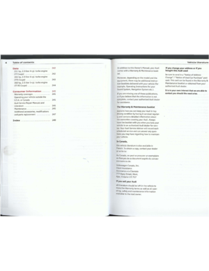 4
4 5
5 6
6 7
7 8
8 9
9 10
10 11
11 12
12 13
13 14
14 15
15 16
16 17
17 18
18 19
19 20
20 21
21 22
22 23
23 24
24 25
25 26
26 27
27 28
28 29
29 30
30 31
31 32
32 33
33 34
34 35
35 36
36 37
37 38
38 39
39 40
40 41
41 42
42 43
43 44
44 45
45 46
46 47
47 48
48 49
49 50
50 51
51 52
52 53
53 54
54 55
55 56
56 57
57 58
58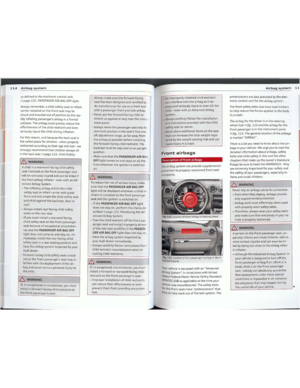 59
59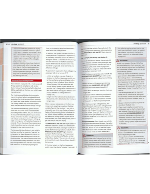 60
60 61
61 62
62 63
63 64
64 65
65 66
66 67
67 68
68 69
69 70
70 71
71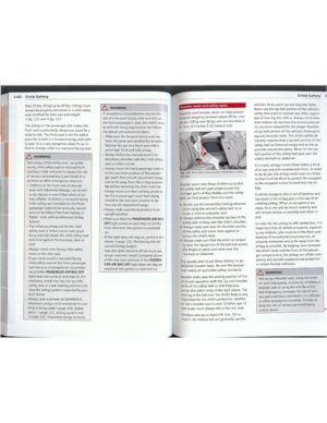 72
72 73
73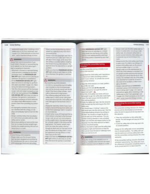 74
74 75
75 76
76 77
77 78
78 79
79 80
80 81
81 82
82 83
83 84
84 85
85 86
86 87
87 88
88 89
89 90
90 91
91 92
92 93
93 94
94 95
95 96
96 97
97 98
98 99
99 100
100 101
101 102
102 103
103 104
104 105
105 106
106 107
107 108
108 109
109 110
110 111
111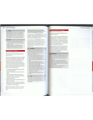 112
112 113
113 114
114 115
115 116
116 117
117 118
118 119
119 120
120 121
121 122
122 123
123 124
124 125
125 126
126 127
127 128
128 129
129 130
130 131
131