Page 177 of 329

13B-177
MR-372-J84-13B050$624.mif
V17
13B
DIESEL INJECTION
Fault finding – Interpretation of statuses
ET703
CRUISE CONTROL/SPEED LIMITER BUTTONS
STATUS DEFINITIONINACTIVE: This status indicates that no button has been pressed.
INCREASE: This status indicates that the increase button is pressed.
DECREASE: This status indicates that the decrease button is pressed.
SUSPEND: This status indicates that the 0 button is pressed.
RESUME: This status indicates that the R button is pressed.
NOTESSpecial notes:
Only perform these tests if the status does not correspond with the system
programming functions.
Use the Wiring Diagram Technical Note for Mégane II ph2, Scénic II ph2, CLIO III,
MODUS and Kangoo II.
INACTIVE
Status ET703 becomes INACTIVE when the cruise control/speed limiter button is not
pressed. These buttons are located on the steering wheel.
Refer to the airbag technical note for the vehicle for details on removal of the driver's
airbag and carrying out the checks in complete safety (see 88C, Airbag and
pretensioners).
If status ET703 does not display INACTIVE,
●check the condition of the cruise control/speed limiter +/- button and the
condition of its connector.
●check the condition of the cruise control/speed limiter "R/0" button and the
condition of its connector,
If the connectors are faulty and if there is a repair procedure (see Te c h n i c a l N o t e
6015A, Electrical wiring repair, Wiring: Precautions for repair), repair the
connector(s), otherwise replace the wiring.
AFTER REPAIRCarry out a road test, then check with the diagnostic tool.
SID301_V44_ET703/SID304_V45_ET703/SID301_V48_ET703/SID304_V49_ET703/SID304_V4D_ET703/SID301_V4C_ET703
Siemens Injection
SID301 and 304
Vdiag No.: 44-45-48-49-4D-4C
Program No.: B2
Page 178 of 329

13B-178
MR-372-J84-13B050$624.mif
V17
Siemens Injection
SID301 and 304
Vdiag No.: 44-45-48-49-4D-4C
Program No.: B2DIESEL INJECTION
Fault finding – Interpretation of statuses13B
ET703
CONTINUED 1
INCREASE
Status ET703 becomes INCREASE when the cruise control/speed limiter + button is
pressed. This button is on the steering wheel, on the left-hand side.
Refer to the airbag technical note for the vehicle for details on removal of the driver's
airbag and carrying out the checks in complete safety (see 88C, Airbag and
pretensioners).
If status ET703 does not display INCREASE, check the status of the cruise control/
speed limiter +/- button, and the condition of its connector.
If the connector is faulty and if there is a repair method (see Technical Note 6015A,
Repairing electrical wiring, wiring: Precautions for repair), repair the connector(s);
otherwise replace the wiring.
Measure the resistance on the following connections while pressing the + button
(on the button tracks):
●Connection code86G of component 331.
●Connection code 86M of component 331.
If the resistance is not approximately 300Ω, check the continuity of the connection for
the button when the button is in the rest position.
If there is continuity, replace the +/- control button (see MR 392, 385, 364, 370 and 417
Mechanical, 83D, Cruise control, Switch on the steering wheel: Removal -
Refitting).
If the connection or connections are faulty and there is a repair procedure
(seeTechnical Note 6015A, Electrical wiring repair, Wiring: Precautions for
repair), repair the wiring, otherwise replace it.
AFTER REPAIRCarry out a road test, then check with the diagnostic tool.
Page 179 of 329

13B-179
MR-372-J84-13B050$624.mif
V17
Siemens Injection
SID301 and 304
Vdiag No.: 44-45-48-49-4D-4C
Program No.: B2DIESEL INJECTION
Fault finding – Interpretation of statuses13B
ET703
CONTINUED 2
DECREASE
Status ET703 becomes DECREASE when the cruise control/speed limiter button is
pressed. This button is on the steering wheel, on the left-hand side.
Refer to the airbag technical note for the vehicle for details on removal of the driver's
airbag and carrying out the checks in complete safety (see 88C, Airbag and
pretensioners).
If status ET703 does not change to DECREASE, check the status of the cruise control/
speed limiter +/- button and check the condition of its connector.
If the connector is faulty and if there is a repair method (see Technical Note 6015A,
Repairing electrical wiring, wiring: Precautions for repair), repair the connector(s);
otherwise replace the wiring.
If the connection or connections are faulty and there is a repair procedure (see
Technical Note 6015A, Electrical wiring repair, Wiring: Precautions for repair),
repair the wiring, otherwise replace it.
Measure the resistance of the following connections while pressing the "-" button
(on the button tracks):
●Connection code86G of component 331.
●Connection code 86M of component 331.
If the resistance is not approximately 100Ω, check the continuity of the button when the
button is in the rest position.
If there is continuity, replace the +/- control button.
If the connection or connections are faulty and there is a repair procedure (see
Technical Note 6015A, Electrical wiring repair, Wiring: Precautions for repair),
repair the wiring, otherwise replace it.
SUSPENDStatus ET703 becomes SUSPEND when the cruise control/speed limiter "0" button is
pressed. This button is located on the steering wheel, to the right.
Refer to the airbag technical note for the vehicle for details on removal of the driver's
airbag and carrying out the checks in complete safety (see 88C, Airbag and
pretensioners).
If status ET703 does not become SUSPEND, check the status of the cruise control/
speed limiter R/0 button and the condition of its connector.
If the connector is faulty and if there is a repair method (see Technical Note 6015A,
Repairing electrical wiring, Wiring: Precautions for repair), repair the wiring,
otherwise replace the wiring.
Measure the resistance of the following connections while pressing the 0 button
(on the button tracks):
●Connection code86G of component 331.
●Connection code 86M of component 331.
If the resistance is not approximately 0Ω, replace the R/0 control button.
If there is continuity, replace the R/0 control button.
If the connection or connections are faulty and there is a repair procedure
(seeTechnical Note 6015A, Electrical wiring repair, Wiring: Precautions for
repair), repair the wiring, otherwise replace it.
AFTER REPAIRCarry out a road test, then check with the diagnostic tool.
Page 180 of 329

13B-180
MR-372-J84-13B050$624.mif
V17
Siemens Injection
SID301 and 304
Vdiag No.: 44-45-48-49-4D-4C
Program No.: B2DIESEL INJECTION
Fault finding – Interpretation of statuses13B
ET703
CONTINUED 3
RESUME
Status ET703 becomes RESUME when the cruise control/speed limiter "R" button is
pressed. This button is located on the steering wheel, to the right.
Refer to the airbag technical note for the vehicle for details on removal of the driver's
airbag and carrying out the checks in complete safety (see 88C, Airbag and
pretensioners).
If status ET703 does not change to RESUME, check the status of the cruise control/
speed limiter R/0 button and the condition of its connector.
If the connector is faulty and if there is a repair method (see Technical Note 6015A,
Repairing electrical wiring, wiring: Precautions for repair), repair the connector(s);
otherwise replace the wiring.
If the connector is faulty and if there is a repair method (see Technical Note 6015A,
Repairing electrical wiring, Wiring: Precautions for repair), repair the wiring,
otherwise replace the wiring. Measure the resistance of the following connections
while pressing the R button (on the button tracks):
●Connection code86G of component 331.
●Connection code 86M of component 331.
If the resistance is not approximately 900 Ω, check the continuity of the connection
when the button is in the rest position.
If there is continuity, replace the R/0 control button.
If the connection or connections are faulty and there is a repair procedure
(seeTechnical Note 6015A, Electrical wiring repair, Wiring: Precautions for
repair), repair the wiring, otherwise replace the wiring.
AFTER REPAIRCarry out a road test, then check with the diagnostic tool.
Page 181 of 329

13B-181
MR-372-J84-13B050$624.mif
V17
Siemens Injection
SID301 and 304
Vdiag No.: 44-45-48-49-4D-4C
Program No.: B2DIESEL INJECTION
Fault finding – Interpretation of statuses13B
ET704
ET705
BRAKE SWITCH NO. 1
BRAKE SWITCH NO. 2
STATUS DEFINITIONACTIVE: This status indicates that the brake pedal is depressed.
INACTIVE This status indicates that the brake pedal is released.
NOTESSpecial note:
Only perform these tests if the status does not correspond with the system
programming functions.
Use the Wiring Diagram Technical Note for Mégane II ph2, Scénic II ph2, CLIO III,
MODUS and Kangoo II.
Note:
Statuses ET704 and ET705 should change status at the same time. If they do not, consult the interpretation of
faults DF008 Pedal potentiometer circuit gang 1 and DF009 Pedal potentiometer circuit gang 2.
ACTIVE
If the brake lights are working:
– check the continuity and make sure there is no interference resistance on the
following connection:
Connection code 5A between components 160 and 120, 645 and 119.
If the connection is faulty and there is a repair procedure (see Technical Note 6015A,
Electrical wiring repair, Wiring: Precautions for repair), repair the wiring, otherwise
replace it.
If the brake lights are not operational, check:
– the condition and fitting of the brake switch,
– the condition and conformity of the brake light fuse,
– the conformity of the values in the following table:
Continuity between
connectionsInsulation between
connections
Switch pressed
(Brake pedal released)5A and BPT 65G and SP17
Switch released
(Brake pedal depressed)65G and SP17 5A and BPT
or
INACTIVE
AFTER REPAIRCarry out a road test, then check with the diagnostic tool.
SID301_V44_ET704/SID304_V45_ET704/SID301_V48_ET704/SID304_V49_ET704/SID304_V4D_ET704/SID301_V4C_ET704
SID301_V44_ET705/SID304_V45_ET705/SID301_V48_ET705/SID304_V49_ET705/SID304_V4D_ET705/SID301_V4C_ET705
Page 182 of 329
13B-182
MR-372-J84-13B050$624.mif
V17
Siemens Injection
SID301 and 304
Vdiag No.: 44-45-48-49-4D-4C
Program No.: B2DIESEL INJECTION
Fault finding – Interpretation of statuses13B
ET704
ET705
CONTINUED
INACTIVE
CONTINUED
If the connection or connections are faulty and there is a repair procedure
(seeTechnical Note 6015A, Electrical wiring repair, Wiring: Precautions for
repair), repair the wiring, otherwise replace it.
If the values obtained are not correct, replace the brake switch (see MR 392, 385, 364,
370 and 417 Mechanical, 37A, Mechanical component controls, Brake light
switch: Removal - Refitting).
AFTER REPAIRCarry out a road test, then check with the diagnostic tool.
Page 183 of 329

13B-183
MR-372-J84-13B050$624.mif
V17
Siemens Injection
SID301 and 304
Vdiag No.: 44-45-48-49-4D-4C
Program No.: B2DIESEL INJECTION
Fault finding – Interpretation of statuses13B
ET706
ET707
ET708
ET709
ET710
ET711
ET712
ET713
ET714
ET715STORED ENGINE STATUS NO. 1
STORED ENGINE STATUS NO. 2
STORED ENGINE STATUS NO. 3
STORED ENGINE STATUS NO. 4
STORED ENGINE STATUS NO. 5
STORED ENGINE STATUS NO. 6
STORED ENGINE STATUS NO. 7
STORED ENGINE STATUS NO. 8
STORED ENGINE STATUS NO. 9
STORED ENGINE STATUS NO. 10
STATUS DEFINITIONRUNNING: This status indicates that the stored engine status is engine running.
STOPPED: This status indicates that the stored engine status is engine stopped.
NOTESSpecial note:
Check the interpretation of these parameters only on ALP21 Particle filter warning
light illuminated.
Vdiag 4D and 49 only.
Each STATUS between ET706 and ET715 corresponds to regeneration failures for which the mileage is recorded
by the parameters PR794 Regeneration failure record No. 1 to PR803 Regeneration failure record No. 10
(for example: PR797 Regeneration failure record No. 4 is linked to ET709 Stored engine status no. 4).
"RUNNING"
The status is ACTIVE as soon as the ignition is switched on.
"STOPPED"If the status is STOPPED, regeneration failure due to the engine being switched off.
+ APCDo not interpret this engine status.
"NONE"Do not interpret this engine status.
AFTER REPAIRCarry out a road test, then check with the diagnostic tool.
SID304_V4D_ET706/SID304_V4D_ET707/SID304_V4D_ET708/SID304_V4D_ET709/SID304_V4D_ET710/SID304_V4D_ET711/
SID304_V4D_ET712/SID304_V4D_ET713/SID304_V4D_ET714/SID304_V4D_ET715/SID304_V49_ET706/SID304_V49_ET707/
SID304_V49_ET708/SID304_V49_ET709/SID304_V49_ET710/SID304_V49_ET711/SID304_V49_ET712/SID304_V49_ET713/
SID304_V49_ET714/SID304_V49_ET715/SID301_V4C_ET707/SID301_V4C_ET708/SID301_V4C_ET709/SID301_V4C_ET710/
SID301_V4C_ET711/SID301_V4C_ET712/SID301_V4C_ET713/SID301_V4C_ET714/SID301_V4C_ET715
Page 184 of 329

13B-184
MR-372-J84-13B050$624.mif
V17
13B
DIESEL INJECTION
Fault finding – Interpretation of statuses
ET741
OPTIONAL VEHICLE SPEED RESTRICTION
STATUS DEFINITIONACTIVE: This status indicates that the speed restriction is activated.
INACTIVE: This status indicates that the speed restriction is deactivated.
NOTESSpecial notes:
Only perform these tests if the status does not correspond with the system
programming functions.
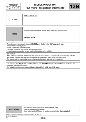
This status indicates whether the vehicle speed restriction is a customer option, using
the command SC040 Speed limiter.
Kangoo II only.
Conformity check with the engine stopped and the ignition on, or engine running, and engine coolant
temperature > 80°C
ACTIVE
INACTIVE
Vehicle speed restricted using command SC040 Speed limiter.
See the interpretation of parameter PR879 Maximum speed authorized to find the
configured speed restriction.
Optional speed restriction function deactivated.
AFTER REPAIRCarry out a road test, then check with the diagnostic tool.
SID301_V48_ET741/SID304_V4D_ET741/SID301_V4C_ET741
Siemens Injection
SID301 and 304
Vdiag No.: 44-45-48-49-4D-4C
Program No.: B1 and B2