2011 RENAULT SCENIC battery replacement
[x] Cancel search: battery replacementPage 26 of 329

13B-26
MR-372-J84-13B050$273.mif
V17
13B
DIESEL INJECTION
Fault finding – Replacement of components
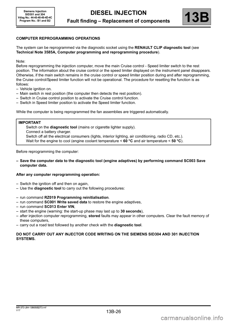
COMPUTER REPROGRAMMING OPERATIONS
The system can be reprogrammed via the diagnostic socket using the RENAULT CLIP diagnostic tool (see
Technical Note 3585A, Computer programming and reprogramming procedure).
Note:
Before reprogramming the injection computer, move the main Cruise control - Speed limiter switch to the rest
position. The information about the cruise control or the speed limiter displayed on the instrument panel disappears.
Otherwise, if the main switch remains in the cruise control or speed limiter position during and after reprogramming,
the Cruise control/Speed limiter function will not be operational. The procedure for resetting the function is as
follows:
– Vehicle ignition on.
– Main switch in rest position (the computer then detects the rest position).
– Switch in Cruise control position to activate the Cruise control function.
– Switch in Speed limiter position to activate the Speed limiter function.
While the computer is being reprogrammed the fan assemblies are triggered automatically.
Before reprogramming the computer:
– Save the computer data to the diagnostic tool (engine adaptives) by performing command SC003 Save
computer data.
After any computer reprogramming operation:
– Switch the ignition off and then on again,
–Use the diagnostic tool to carry out the following procedures:
– run command RZ019 Programming reinitialisation.
– run command SC001 Write saved data to restore the engine adaptives,
– run command SC013 Enter VIN,
– start the engine (warning: the start-up phase may last up to 30 seconds),
– after injection computer reprogramming, stored faults may appear in other computers. Clear the fault memory of
these computers,
– carry out a road test followed by another check with the diagnostic tool.
DO NOT CARRY OUT ANY INJECTOR CODE WRITING ON THE SIEMENS SID304 AND 301 INJECTION
SYSTEMS.IMPORTANT
Switch on the diagnostic tool (mains or cigarette lighter supply).
Connect a battery charger.
Switch off all the electrical consumers (lights, interior lighting, air conditioning, radio CD, etc.).
Wait for the engine to cool (engine coolant temperature < 60 °C and air temperature < 50 °C).
MR-372-J84-13B050$273.mif
Siemens Injection
SID301 and 304
Vdiag No.: 44-45-48-49-4D-4CProgram No.: B1 and B2
Page 28 of 329

13B-28
MR-372-J84-13B050$273.mif
V17
Siemens Injection
SID301 and 304
Vdiag No.: 44-45-48-49-4D-4C
Program No.: B1 and B2DIESEL INJECTION
Fault finding – Replacement of components13B
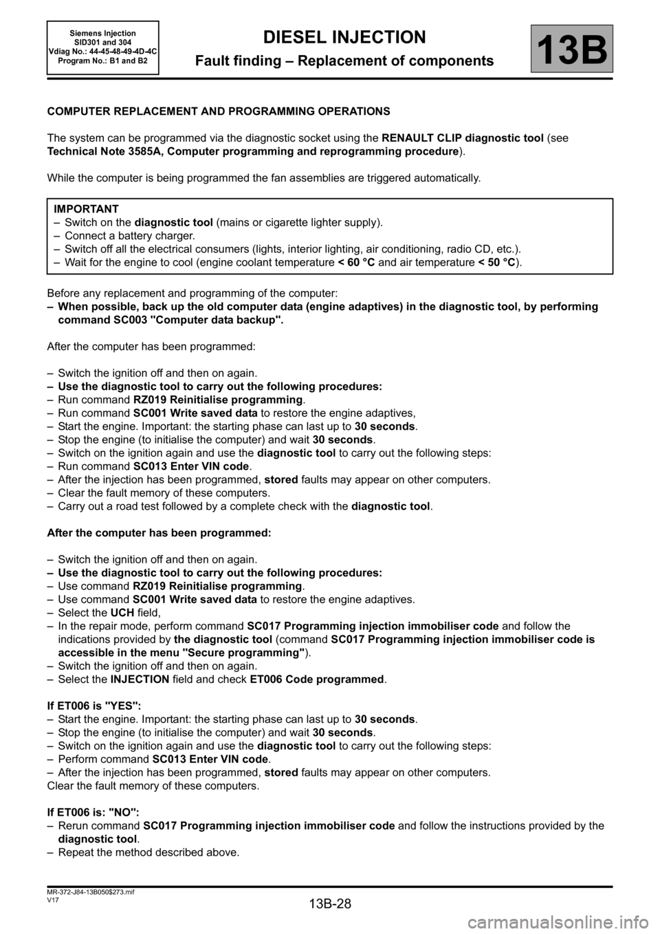
COMPUTER REPLACEMENT AND PROGRAMMING OPERATIONS
The system can be programmed via the diagnostic socket using the RENAULT CLIP diagnostic tool (see
Technical Note 3585A, Computer programming and reprogramming procedure).
While the computer is being programmed the fan assemblies are triggered automatically.
Before any replacement and programming of the computer:
– When possible, back up the old computer data (engine adaptives) in the diagnostic tool, by performing
command SC003 "Computer data backup".
After the computer has been programmed:
– Switch the ignition off and then on again.
– Use the diagnostic tool to carry out the following procedures:
– Run command RZ019 Reinitialise programming.
– Run command SC001 Write saved data to restore the engine adaptives,
– Start the engine. Important: the starting phase can last up to 30 seconds.
– Stop the engine (to initialise the computer) and wait 30 seconds.
– Switch on the ignition again and use the diagnostic tool to carry out the following steps:
– Run command SC013 Enter VIN code.
– After the injection has been programmed, stored faults may appear on other computers.
– Clear the fault memory of these computers.
– Carry out a road test followed by a complete check with the diagnostic tool.
After the computer has been programmed:
– Switch the ignition off and then on again.
– Use the diagnostic tool to carry out the following procedures:
– Use command RZ019 Reinitialise programming.
– Use command SC001 Write saved data to restore the engine adaptives.
– Select the UCH field,
– In the repair mode, perform command SC017 Programming injection immobiliser code and follow the
indications provided by the diagnostic tool (command SC017 Programming injection immobiliser code is
accessible in the menu "Secure programming").
– Switch the ignition off and then on again.
– Select the INJECTION field and check ET006 Code programmed.
If ET006 is "YES":
– Start the engine. Important: the starting phase can last up to 30 seconds.
– Stop the engine (to initialise the computer) and wait 30 seconds.
– Switch on the ignition again and use the diagnostic tool to carry out the following steps:
– Perform command SC013 Enter VIN code.
– After the injection has been programmed, stored faults may appear on other computers.
Clear the fault memory of these computers.
If ET006 is: "NO":
– Rerun command SC017 Programming injection immobiliser code and follow the instructions provided by the
diagnostic tool.
– Repeat the method described above.IMPORTANT
– Switch on the diagnostic tool (mains or cigarette lighter supply).
– Connect a battery charger.
– Switch off all the electrical consumers (lights, interior lighting, air conditioning, radio CD, etc.).
– Wait for the engine to cool (engine coolant temperature < 60 °C and air temperature < 50 °C).
Page 59 of 329

13B-59
MR-372-J84-13B050$390.mif
V17
DIESEL INJECTION
Fault finding – Interpretation of faults
Siemens Injection
SID301 and 304
Vdiag No. 44-45-48-49-4D-4C
Program No.: B1 and B2
13B
DF047
PRESENT
OR
STOREDCOMPUTER SUPPLY VOLTAGE
1. DEF: Signal outside lower limit
2. DEF: Signal outside upper limit
NOTESProcessing priority in the event of a number of faults:
Deal with fault DF532 Alternator charge signal first if the fault is present or stored.
Conditions for applying the fault finding procedure to a stored fault:
– The fault is declared present with the engine running.
Use CLIO III, MODUS, MEGANE II ph2, SCENIC II ph2 and KANGOO II Wiring
diagrams Technical Note.
Check the battery and run fault finding on the charging circuit (see Technical Note 6014A, Checking the
charging circuit or 87G, Engine compartment connection unit).
Check the connection and condition of the injection computer connectors, component code 120 (see MR 392,
385, 364, 370 and 417, Mechanical, 13B, Diesel injection, Diesel injection computer: Removal - Refitting).
If the connectors are faulty and if there is a repair procedure (see Technical Note 6015A, Repairing electrical
wiring, Wiring: Precautions for repair) repair the connector(s); otherwise, replace the wiring.
Check the engine and chassis earths.
Check the condition of the relay support plate as well as the positioning and condition of the injection supply
relay, component code 983.
Replace the relay if necessary (see Replacement of components).
With the ignition on, check for the presence of +12 V on the connectionsBP of the main relay support plate,
component code 983 or the Protection and Switching Unit computer, component code 1337.
If the connection is faulty and there is a repair procedure (see Technical Note 6015A, Electrical wiring repair,
Wiring: Precautions for repair), repair the wiring, otherwise replace it.
Check the insulation, continuity and the absence of interference resistance on the following connections:
–3FB between components983 and 120,
–M between components120 and ME (Bodywork electrical earth).
Or (for Kangoo II):
–3FB1 between components 1337 and 120,
–3FB2 between components 1337 and 120,
–N between component 120 and the earth.
If the connection(s) are faulty and there is a repair method (see Technical Note 6015A, Repairing electrical
wiring, Wiring: Precautions for repair), repair the wiring, otherwise replace it.
If the fault is still present, contact the Techline.
AFTER REPAIRDeal with any faults displayed by the diagnostic tool.
Clear the computer fault memory.
Carry out a road test followed by another check with the diagnostic tool.
SID301_V44_DF047 / SID304_V45_DF047 / SID301_V48_DF047 / SID304_V49_DF047 / SID304_V4D_DF047 / SID301_V4C_DF047
Page 304 of 329

13B-304
MR-372-J84-13B050$936.mif
V17
DIESEL INJECTION
Fault finding – Tests13B
Siemens Injection
SID301 and 304
Vdiag No.: 44-45-48-49-4D-4C
Program No.: B1 and B2
TEST 3 High pressure fuel pressure solenoid valve check
NOTESConditions prior to test:
The entire low pressure system must be in good condition.
Check the sealing of the high pressure pipes and unions.
Cause:
Rail pressure approximately 50 bar during starting.
Use CLIO III, MODUS, MEGANE II ph2, SCENIC II ph2 and Kangoo II Wiring
diagrams Technical Note.
Disconnect the fuel pressure solenoid valve
connector and measure the resistance at the
terminals of the fuel-pressure solenoid valve
between connection 3ZQ of connector B
computer and connection 3FB (or 3FB3 for
Kangoo II) of the Protection and Communication
Unit or the main injection relay.
Is the resistance between 1.5 Ω and 15 Ω?
YES
Check the wiring between the injection computer
and the fuel pressure solenoid valve.
Measure the voltage at connection 3FB on the
connector of the fuel pressure solenoid valve
with the ignition on.
Is the voltage the same as the battery voltage?
YES
Apply the conformity check for ET613 Fuel
pressure regulator
NOReplace the pump (see Replacement of
components).
NOCheck the connection and condition of the
connectors for the fuel pressure solenoid
valve and the main injection relay.
– connection code 3FB1 (or 3FB3 for
Kangoo II) between components
1105 and 983 or 1337.
If the connection is faulty and there is a
repair procedure (see Technical Note
6015A, Electrical wiring repair, Wiring:
Precautions for repair), repair the wiring,
otherwise replace it. Check the main
injection relay.
AFTER REPAIRCarry out a road test followed by a complete check with the diagnostic tool.
SID301_V44_TEST3 / SID304_V45_TEST3 / SID301_V48_TEST3 / SID304_V49_TEST3 / SID304_V4D_TEST3 / SID301_V4C_TEST3