Page 121 of 329

13B-121
MR-372-J84-13B050$468.mif
V17
DIESEL INJECTION
Fault finding – Interpretation of faults
Siemens Injection
SID301 and 304
Vdiag No.: 44-45-48-49-4D-4C
Program No.: B1 and B2
13B
DF1009
PRESENT
OR
STOREDCATALYTIC CONVERTER 1 DOWNSTREAM TEMPERATURE
REGULATION
1. DEF: Signal outside lower limit
2. DEF: Signal outside upper limit
NOTESConditions for applying the fault finding procedure to a stored fault:
The fault becomes present after a road test with particle filter regeneration.
Special notes:
If the fault is present:
The level 1 fault warning light is lit on the instrument panel.
Use CLIO III, MODUS, MEGANE II ph2, SCENIC II ph2 and Kangoo II Wiring
diagrams Technical Note.
Check the connection and condition of the connector of the catalytic converter 1 downstream temperature
sensor, component code 1765.
If the connector is faulty and there is a repair procedure (see Technical Note 6015A, Electrical wiring repair,
Wiring: Precautions for repair), repair the connector, otherwise replace the wiring.
Check the connection and condition of the injection computer connector, component code 120 (see MR 392,
385, 364, 370 and 417, Mechanical, 13B, Diesel injection, Diesel injection computer: Removal - Refitting).
If the connector is faulty and there is a repair procedure (see Technical Note 6015A, Electrical wiring repair,
Wiring: Precautions for repair), repair the connector, otherwise replace the wiring.
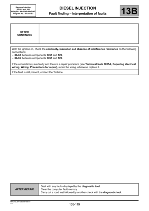
With the ignition on, check the continuity, insulation and absence of interference resistance on the following
connections:
–3AGX between components 1765 and 120,
–3AGY between components 1765 and 120.
If the connection(s) are faulty and there is a repair method (see Technical Note 6015A, Repairing electrical
wiring, Wiring: Precautions for repair), repair the wiring, otherwise replace it.
If the fault is still present, replace the turbine upstream temperature sensor.
While the engine is idling, check the return flow rate at the injectors.
After 5minutes the return volume must be between 16 mland 24 ml per injector.
If this tolerance is incorrect, replace the faulty injector(s).
Check the temperature of the catalytic converter; check that it is not too low.
Check that the exhaust system is not pierced.
Replace any faulty components.
AFTER REPAIRDeal with any faults displayed by the diagnostic tool.
Clear the computer fault memory.
Carry out a road test followed by another check with the diagnostic tool.
SID301_V44_DF1009 / SID304_V45_DF1009 / SID301_V48_DF1009 / SID304_V49_DF1009 / SID304_V4D_DF1009 / SID301_V4C_DF1009
Page 122 of 329
13B-122
MR-372-J84-13B050$468.mif
V17
DIESEL INJECTION
Fault finding – Interpretation of faults
Siemens Injection
SID301 and 304
Vdiag No.: 44-45-48-49-4D-4C
Program No.: B1 and B2
13B
DF1009
CONTINUED
Measure the resistance of the catalytic converter 1 downstream temperature sensor, component code 1765
between connections 3AGX and 3AGY.
6886Ω
2565Ω
1192Ω
404Ω
267Ω
If the resistance does not match these values, replace the catalytic converter downstream temperature
sensor.
AFTER REPAIRDeal with any faults displayed by the diagnostic tool.
Clear the computer fault memory.
Carry out a road test followed by another check with the diagnostic tool.
Page 123 of 329

13B-123
MR-372-J84-13B050$468.mif
V17
DIESEL INJECTION
Fault finding – Interpretation of faults
Siemens Injection
SID301 and 304
Vdiag No.: 44-45-48-49-4D-4C
Program No.: B1 and B2
13B
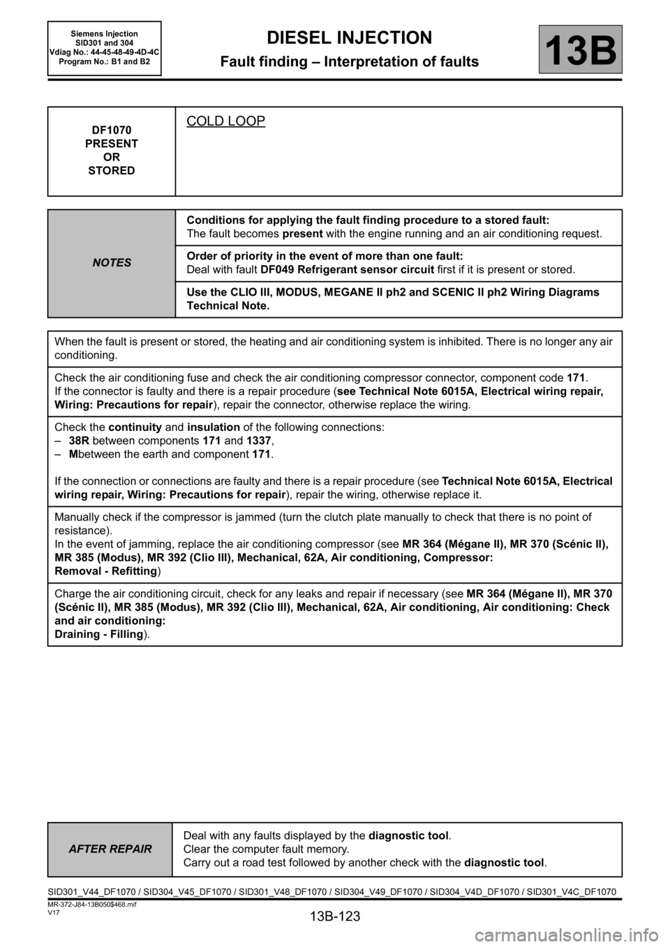
DF1070
PRESENT
OR
STOREDCOLD LOOP
NOTESConditions for applying the fault finding procedure to a stored fault:
The fault becomes present with the engine running and an air conditioning request.
Order of priority in the event of more than one fault:
Deal with fault DF049 Refrigerant sensor circuit first if it is present or stored.
Use the CLIO III, MODUS, MEGANE II ph2 and SCENIC II ph2 Wiring Diagrams
Technical Note.
When the fault is present or stored, the heating and air conditioning system is inhibited. There is no longer any air
conditioning.
Check the air conditioning fuse and check the air conditioning compressor connector, component code 171.
If the connector is faulty and there is a repair procedure (see Technical Note 6015A, Electrical wiring repair,
Wiring: Precautions for repair), repair the connector, otherwise replace the wiring.
Check the continuity and insulation of the following connections:
– 38R between components 171 and 1337,
– Mbetween the earth and component 171.
If the connection or connections are faulty and there is a repair procedure (see Technical Note 6015A, Electrical
wiring repair, Wiring: Precautions for repair), repair the wiring, otherwise replace it.
Manually check if the compressor is jammed (turn the clutch plate manually to check that there is no point of
resistance).
In the event of jamming, replace the air conditioning compressor (see MR 364 (Mégane II), MR 370 (Scénic II),
MR 385 (Modus), MR 392 (Clio III), Mechanical, 62A, Air conditioning, Compressor:
Removal - Refitting)
Charge the air conditioning circuit, check for any leaks and repair if necessary (see MR 364 (Mégane II), MR 370
(Scénic II), MR 385 (Modus), MR 392 (Clio III), Mechanical, 62A, Air conditioning, Air conditioning: Check
and air conditioning:
Draining - Filling).
AFTER REPAIRDeal with any faults displayed by the diagnostic tool.
Clear the computer fault memory.
Carry out a road test followed by another check with the diagnostic tool.
SID301_V44_DF1070 / SID304_V45_DF1070 / SID301_V48_DF1070 / SID304_V49_DF1070 / SID304_V4D_DF1070 / SID301_V4C_DF1070
Page 124 of 329
13B-124
MR-372-J84-13B050$507.mif
V17
13B
DIESEL INJECTION
Fault finding – Conformity check
The global conformity check for the functions and sub-functions of this system is no longer interpreted in the
conformity check. Instead, all information available in the functions and sub-functions can be found in the
following sections:
For STATUSES, refer to the INTERPRETATION OF STATUSES section.
For PARAMETERS, refer to the INTERPRETATION OF PARAMETERS section.
For COMMANDS, refer to the INTERPRETATION OF COMMANDS section.
SID301_V44_CCONF/SID304_V45_CCONF/SID301_V48_CCONF/SID304_V49_CCONF/SID304_V4D_CCONF/SID301_V4C_CCONF
MR-372-J84-13B050$507.mif
Siemens Injection
SID301 and 304
Vdiag No.: 44-45-48-49-4D-4C
Program No.: B1 and B2
Page 125 of 329

13B-125
MR-372-J84-13B050$546.mif
V17
13B
DIESEL INJECTION
Fault finding – Status summary table
Tool status Diagnostic tool title
ET001Computer + after ignition feed
ET003Engine immobiliser
ET004 Air conditioning authorisation
ET006Code programmed
ET021High speed fan assembly request
ET022Low speed fan assembly request
ET023Fast idle speed request
ET028Level 1 fault warning light request
ET029Level 2 fault warning light request
ET033EGR solenoid valve
ET038Engine
ET042Cruise control/speed limiter
ET076Starting
ET077Impact detected
ET079Air conditioning present
ET088Compressor actuation request
ET121Clutch switch signal
ET148OBD warning light activation request
ET160Preheating relay control
ET228Cylinder 1 injector control
ET229Cylinder 2 injector control
ET230Cylinder 3 injector control
ET231Cylinder 4 injector control
ET238Synchronisation
ET405Clutch pedal switch
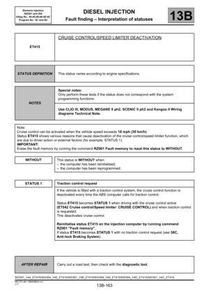
ET415Cruise control/speed limiter deactivation
ET613Fuel pressure regulator
ET638Fuel flow regulator
ET648Engine cooling fan
ET649Water in diesel fuel sensor
ET673Jammed accelerator pedal detected
MR-372-J84-13B050$546.mif
Siemens Injection
SID301 and 304
Vdiag No.: 44-45-48-49-4D-4C
Program No.: B1 and B2
Page 126 of 329
13B-126
MR-372-J84-13B050$546.mif
V17
Siemens Injection
SID301 and 304
Vdiag No.: 44-45-48-49-4D-4C
Program No.: B1 and B2DIESEL INJECTION
Fault finding – Status summary table13B
*elec: electricTool status Diagnostic tool title
ET701Electric fuel pump*. particle filter Only for vehicles equipped with a particle
filter.
ET703Cruise control/speed limiter buttons
ET704Brake switch no. 1
ET705Brake contact no. 2
ET706Stored engine status no. 1
Only for vehicles equipped with a particle
filter (except Vdiag 45) ET707Stored engine status no. 2
ET708Stored engine status no. 3
ET709Stored engine status no. 4
ET710Stored engine status no. 5
ET711Stored engine status no. 6
ET712Stored engine status no. 7
ET713Stored engine status no. 8
ET714Stored engine status no. 9
ET715Stored engine status no. 10
ET741Optional vehicle speed restriction Kangoo II only
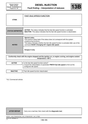
ET800Fast idle speed function Kangoo II only
Page 127 of 329

13B-127
MR-372-J84-13B050$585.mif
V17
13B
DIESEL INJECTION
Fault finding – Interpretation of statuses
ET001
COMPUTER + AFTER IGNITION FEED
STATUS DEFINITION"PRESENT": This status indicates that the + after ignition feed is active.
"ABSENT": This status indicates that the + after ignition feed is not active.
NOTESSpecial notes:
Only perform these tests if the status does not correspond with the system
programming functions.
Use the Mégane II ph2, Scénic II ph2, CLIO III, MODUS and Kangoo II Wiring
Diagram Technical Note.
Conformity check with engine stopped and ignition on, or engine running, and engine coolant temperature
>80 °C
"PRESENT"
NOTESIgnition on.
Normal operating condition.
Use a multimeter to check that there is no +12V with the ignition off on connectionAP15 or AP29 of
component120.
If the connection or connections are faulty and there is a repair method (see Technical Note 6015A, Repairing
electrical wiring, Wiring: Precautions for repair), repair the wiring, otherwise replace it.
"ABSENT"
NOTESIgnition on.
Check the supply fuse
–F18 (5A) (Kangoo II),
–313 (10A) (Modus and Clio),
–F5D (5A) (Mégane II and Scénic II),
of the main supply relay of the injection computer.
Use a multimeter to check for a + 12 V feed on the fuse holder with the ignition on.
If the connection or connections are faulty and there is a repair method (see Technical Note 6015A, Repairing
electrical wiring, Wiring: Precautions for repair), repair the wiring, otherwise replace it.
AFTER REPAIRCarry out a road test, then check with the diagnostic tool.
SID301_V44_ET001/SID304_V45_ET001/SID301_V48_ET001/SID304_V49_ET001/SID304_V4D_ET001/SID301_V4C_ET001
MR-372-J84-13B050$585.mif
Siemens Injection
SID301 and 304
Vdiag No.: 44-45-48-49-4D-4C
Program No.: B1 and B2
Page 128 of 329
13B-128
MR-372-J84-13B050$585.mif
V17
DIESEL INJECTION
Fault finding – Interpretation of statuses
Siemens Injection
SID301 and 304
Vdiag No.: 44-45-48-49-4D-4C
Program No.: B1 and B2
13B
ET001
CONTINUED
Check the continuity and insulation to earth of the following connection:
–AP15 between components1337 and 120
Check the continuity and the absence of interference resistance on the following connection:
–N between the earth and component120 (for Kangoo II),
–NH between the earth and component120 (for Modus, Clio),
–M between the earth and component120 (for Mégane II and Scénic II).
If the connection or connections are faulty and there is a repair method (see Technical Note 6015A, Repairing
electrical wiring, Wiring: Precautions for repair), repair the wiring, otherwise replace it.
AFTER REPAIRCarry out a road test, then check with the diagnostic tool.