2011 RENAULT SCENIC engine coolant
[x] Cancel search: engine coolantPage 146 of 236

13B - 146
DIESEL INJECTION
Fault finding - Conformity check13B
V10 MR-372-J84-13B150$470.mif
EDC16 INJECTION
Program No.: C1
Vdiag No.: 44, 48 and 4C
PROTECTION
NOTESOnly check conformity after a complete check using the diagnostic tool. The values
shown in this conformity check are given as a guide.
Test conditions: engine at idle speed, coolant temperature at > 80°.
Order FunctionParameter or Status
checked or ActionDisplay and Notes Fault finding
1Engine
immobiliserET341: Code
programmedYES
or
NOIf status ET341 is stuck at
NO, (See 87B, UCH).
ET003: Engine
immobiliserACTIVE
or
INACTIVEIf status ET003 is stuck at
ACTIVE, (See 87B, UCH).
2 Vehicle impact ET077: Impact
detectedYES
or
NOIn the event of a fault,
consult the interpretation of
fault DF069 Impact signal
detected.
3 Starting ET076: StartingAUTHORISED:
The injection system
authorises starting
or
PROHIBITED:
The injection system
does not authorise
starting.If status ET076 is
PROHIBITED,
(See 87B, UCH).
Page 152 of 236

13B-152
DIESEL INJECTION
Fault finding - Interpretation of statuses13B
V10 MR-372-J84-13B150$564.mif
EDC16 INJECTION
Program No.: C1
Vdiag No.: 44, 48 and 4C
ET014
FAN ASSEMBLY 1 CHECK
NOTESOnly perform the tests if the statuses do not correspond with the system programming
functions.
Note: Status ET022 Low-speed engine fan request and status ET014 Engine fan assembly check 1 change
their status at the same time.
RUNNING
The low-speed fan assembly is supplied in three scenarios:
– the engine coolant temperature is above 89°C,
– the air conditioning is operating,
– the injection computer has system faults that could lead to the engine overheating.
When the low-speed fan assembly is supplied:
– status ET014 changes to RUNNING
– status ET022 low-speed engine fan request changes to ACTIVE.
In the event that the low-speed engine fan does not work, refer to the UPC fault finding note.
STOPPED
The low-speed fan assembly stops when:
– the engine coolant temperature is below 89°C,
– no air conditioning request made by the driver.
IMPORTANT!WARNING
If the UPC does not detect the injection computer frames, the low-speed engine
fan assembly is supplied until the battery is completely discharged.
In the event that the low-speed engine fan assembly is defective, the high-speed
engine fan assembly will then be activated.
AFTER REPAIRCarry out a road test followed by another check with the diagnostic tool.
EDC16_V44_ET014/EDC16_V48_ET014/EDC16_V4C_ET014
Page 153 of 236

13B-153
DIESEL INJECTION
Fault finding - Interpretation of statuses13B
V10 MR-372-J84-13B150$564.mif
EDC16 INJECTION
Program No.: C1
Vdiag No.: 44, 48 and 4C
ET015
FAN ASSEMBLY 2 CHECK
NOTESOnly perform the tests if the statuses do not correspond with the system programming
functions.
Note: Status ET015 Engine fan assembly 2 and status ET021 High-speed engine fan request change their
status at the same time.
RUNNING
The engine fan assembly can be supplied when:
– the engine coolant temperature is above 99°C.
– the injection computer has system faults that could lead to the engine overheating.
When the high speed fan is supplied:
– status ET015 changes to RUNNING
– status ET021 low-speed engine fan request changes to ACTIVE.
In the event that the high-speed engine fan does not work, refer to the UPC fault finding note.
STOPPED
The high-speed fan assembly stops when:
– the engine coolant temperature is below 99°C;
IMPORTANT!WARNING
If the UPC does not detect the injection computer frames, the low speed engine
fan is supplied until the battery is completely discharged.
In the event that the low-speed engine fan assembly is defective, the high-speed
engine fan assembly will then be activated.
AFTER REPAIRCarry out a road test followed by another check with the diagnostic tool.
EDC16_V44_ET015/EDC16_V48_ET015/EDC16_V4C_ET015
Page 154 of 236

13B-154
DIESEL INJECTION
Fault finding - Interpretation of statuses13B
V10 MR-372-J84-13B150$564.mif
EDC16 INJECTION
Program No.: C1
Vdiag No.: 44, 48 and 4C
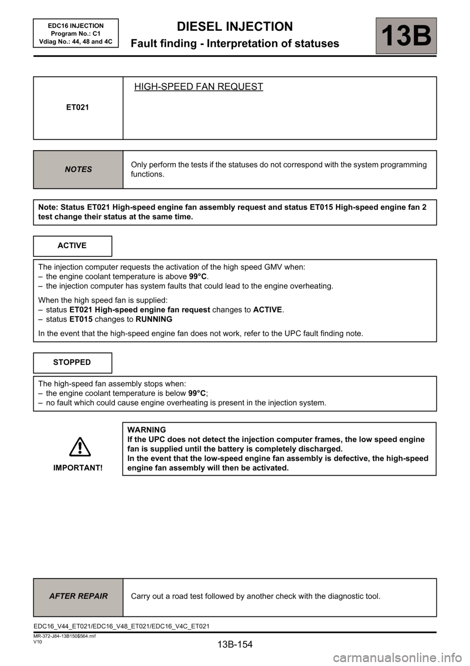
ET021
HIGH-SPEED FAN REQUEST
NOTESOnly perform the tests if the statuses do not correspond with the system programming
functions.
Note: Status ET021 High-speed engine fan assembly request and status ET015 High-speed engine fan 2
test change their status at the same time.
ACTIVE
The injection computer requests the activation of the high speed GMV when:
– the engine coolant temperature is above 99°C.
– the injection computer has system faults that could lead to the engine overheating.
When the high speed fan is supplied:
– status ET021 High-speed engine fan request changes to ACTIVE.
– status ET015 changes to RUNNING
In the event that the high-speed engine fan does not work, refer to the UPC fault finding note.
STOPPED
The high-speed fan assembly stops when:
– the engine coolant temperature is below 99°C;
– no fault which could cause engine overheating is present in the injection system.
IMPORTANT!WARNING
If the UPC does not detect the injection computer frames, the low speed engine
fan is supplied until the battery is completely discharged.
In the event that the low-speed engine fan assembly is defective, the high-speed
engine fan assembly will then be activated.
AFTER REPAIRCarry out a road test followed by another check with the diagnostic tool.
EDC16_V44_ET021/EDC16_V48_ET021/EDC16_V4C_ET021
Page 155 of 236

13B-155
DIESEL INJECTION
Fault finding - Interpretation of statuses13B
V10 MR-372-J84-13B150$564.mif
EDC16 INJECTION
Program No.: C1
Vdiag No.: 44, 48 and 4C
Note: Status ET022 Low-speed engine fan request and status ET014 Engine fan assembly check 1 change
their status at the same time.ET022
LOW-SPEED FAN REQUEST
NOTESOnly perform the tests if the statuses do not correspond with the system programming
functions.
ACTIVE
The injection computer requests the activation of the low speed GMV when:
– the engine coolant temperature is above 89°C,
– the injection computer has system faults that could lead to the engine overheating,
– the air conditioning is switched on by the driver.
When the high speed fan is supplied:
– status ET022 High-speed engine fan request changes to ACTIVE,
– status ET014 changes to RUNNING.
In the event that the low-speed engine fan does not work, refer to the UPC fault finding note.
STOPPED
The low-speed fan assembly stops when:
– the engine coolant temperature is below 89°C,
– no fault which could cause engine overheating is present in the injection system.
– the air conditioning is not switched on by the driver.
IMPORTANT!WARNING
If the UPC does not detect the injection computer frames, the low speed engine
fan is supplied until the battery is completely discharged.
In the event that the low-speed engine fan assembly is defective, the high-speed
engine fan assembly will then be activated.
AFTER REPAIRCarry out a road test followed by another check with the diagnostic tool.
EDC16_V44_ET022/EDC16_V48_ET022/EDC16_V4C_ET022
Page 168 of 236

13B-168
DIESEL INJECTION
Fault finding - Interpretation of statuses13B
V10 MR-372-J84-13B150$564.mif
EDC16 INJECTION
Program No.: C1
Vdiag No.: 44, 48 and 4C
ET405
CLUTCH PEDAL SWITCH
STATUS
DEFINITIONACTIVE: This status indicates that the clutch pedal is depressed.
INACTIVE: This status indicates that the clutch pedal is released.
NOTESSpecial note:
Only perform the tests if the statuses do not correspond with the system programming
functions.
Conformity check with engine stopped and ignition on, or engine running, and engine coolant temperature
> 80°C
ACTIVEClutch pedal depressed.
Non-conformity of the brake signals and or the clutch switch signals can cause the
engine to race during gear changes.
In the event of a fault, check the electrical conformity of the sensor.
INACTIVEClutch pedal released.
Non-conformity of the brake signals and or the clutch switch signals can cause the
engine to race during gear changes.
In the event of a fault, check the electrical conformity of the sensor.
Sensor electrical conformity
ACTIVECheck the condition and fitting of the clutch pedal switch.
Remove the clutch pedal switch then check the insulation between tracks 1 and 2, with
the switch in the rest position.
Repeat this operation with the switch depressed and check the continuity between
tracks 1 and 2.
If these two checks are not in order, replace the switch.
AFTER REPAIRDeal with any other faults. Clear the fault memory.
Switch off the ignition and carry out a road test followed by a test with the diagnostic
tool.
ET405
CLUTCH PEDAL SWITCH
STATUS
DEFINITIONACTIVE: This status indicates that the clutch pedal is depressed.
INACTIVE: This status indicates that the clutch pedal is released.
NOTESSpecial note:
Only perform the tests if the statuses do not correspond with the system programming
functions.
Conformity check with engine stopped and ignition on, or engine running, and engine coolant temperature
> 80°C
ACTIVEClutch pedal depressed.
Non-conformity of the brake signals and or the clutch switch signals can cause the
engine to race during gear changes.
In the event of a fault, check the electrical conformity of the sensor.
INACTIVEClutch pedal released.
Non-conformity of the brake signals and or the clutch switch signals can cause the
engine to race during gear changes.
In the event of a fault, check the electrical conformity of the sensor.
Sensor electrical conformity
EDC16_V44_ET405/EDC16_V48_ET405/EDC16_V4C_ET405
Page 181 of 236

13B - 181
DIESEL INJECTION
Fault finding - Parameter summary table13B
V10 MR-372-J84-13B150$611.mif
EDC16 INJECTION
Program No.: C1
Vdiag No.: 44, 48 and 4C
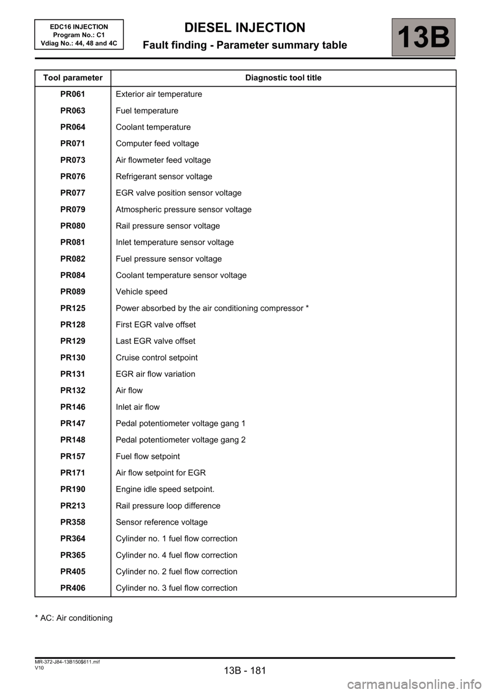
Tool parameter Diagnostic tool title
PR061Exterior air temperature
PR063Fuel temperature
PR064Coolant temperature
PR071Computer feed voltage
PR073Air flowmeter feed voltage
PR076Refrigerant sensor voltage
PR077EGR valve position sensor voltage
PR079Atmospheric pressure sensor voltage
PR080Rail pressure sensor voltage
PR081Inlet temperature sensor voltage
PR082Fuel pressure sensor voltage
PR084Coolant temperature sensor voltage
PR089Vehicle speed
PR125Power absorbed by the air conditioning compressor *
PR128First EGR valve offset
PR129Last EGR valve offset
PR130Cruise control setpoint
PR131EGR air flow variation
PR132Air flow
PR146Inlet air flow
PR147Pedal potentiometer voltage gang 1
PR148Pedal potentiometer voltage gang 2
PR157Fuel flow setpoint
PR171Air flow setpoint for EGR
PR190Engine idle speed setpoint.
PR213Rail pressure loop difference
PR358Sensor reference voltage
PR364Cylinder no. 1 fuel flow correction
PR365Cylinder no. 4 fuel flow correction
PR405Cylinder no. 2 fuel flow correction
PR406Cylinder no. 3 fuel flow correction
* AC: Air conditioning
Page 205 of 236

13B-205
MR-372-J84-13B150$846.mif
V10
DIESEL INJECTION
Fault finding - Fault finding chart13B
ALP 2Starting faults
(or starting impossible)
NOTESBefore dealing with this customer complaint, check that there are no faults,
and he conformity (or otherwise) of the parameters and statuses using the
diagnostic tool.
If the customer complaint is not eliminated, perform the following checks.
Is starting difficult or impossible?
difficult
Check the engine earths.
Make sure that the engine speed reaches 250 rpm when the starter motor is operated, displayed in
the parameter screen.
Ensure that the correct fuel is being used. Run test 5 Diesel fuel conformity check.
Check the conformity of the fuel filter connections.
Ensure that the fuel filter is not saturated with water.
Check there are no air bubbles between the filter and the high pressure pump.
Check the operation of the preheating unit and heater plugs with command AC001 Preheating unit.
Check the condition of the air filter (clogging).
Check the seal of the high-pressure diesel circuit, pump, pipes, unions (visual checks + odours).
Check the position of the EGR valve: jamming or mechanical seizure.
Check the consistency of the signal from the engine coolant temperature sensor.
Check that the pressure regulator is working correctly (see the interpretation of command AC011 Rail
pressure regulator).
Check the operation of the injectors (too much return leakage, clogging, seizing) referring to Component
test, Test 1 Injector Test.
Check the compression balance, according to current consumption during the starting phase
(Compression test menu on the Clip tool).
In the event of imbalance, use a compression gauge to refine the reading (see the procedure in the Workshop
Repair Manual). After the operation, clear the faults caused by disconnecting the regulator and the heater
plugs.
impossible
AFTER REPAIRCarry out a road test followed by a complete check with the diagnostic tool.
EDC16_V44_ALP2 / EDC16_V48_ALP2 / EDC16_V4C_ALP2
EDC16 INJECTION
Program No.: C1
Vdiag No: 44, 48 and 4C