2011 NISSAN TIIDA cowl
[x] Cancel search: cowlPage 511 of 3787

BL-1
BODY
C
DE
F
G H
J
K L
M
SECTION BL
A
B
BL
N
O P
CONTENTS
BODY, LOCK & SECURITY SYSTEM
SERVICE INFORMATION .. ..........................4
PRECAUTIONS .............................................. .....4
Precaution for Supplemental Restraint System
(SRS) "AIR BAG" and "SEAT BELT PRE-TEN-
SIONER" ............................................................. ......
4
Precaution Necessary for Steering Wheel Rota-
tion After Battery Disconnect ............................... ......
4
Precaution for Procedure without Cowl Top Cover ......5
Precaution for Work ..................................................5
PREPARATION ...................................................6
Special Service Tool ........................................... ......6
Commercial Service Tool ..........................................6
SQUEAK AND RATTLE TROUBLE DIAG-
NOSES ................................................................
7
Work Flow ........................................................... ......7
Generic Squeak and Rattle Troubleshooting ............9
Diagnostic Worksheet .............................................11
HOOD .................................................................13
Fitting Adjustment ............................................... ....13
Removal and Installation .........................................14
Removal and Installation of Hood Lock Control .. ....15
Hood Lock Control Inspection .................................17
RADIATOR CORE SUPPORT ....................... ....19
Removal and Installation .........................................19
FRONT FENDER ................................................21
Removal and Installation .........................................21
POWER DOOR LOCK SYSTEM .................... ....22
Component Parts and Harness Connector Loca-
tion ...................................................................... ....
22
System Description .................................................23
CAN Communication System Description ...............25
Schematic ...............................................................26
Wiring Diagram - D/LOCK - .....................................27
Schematic ...............................................................31
Wiring Diagram - D/LOCK - .....................................32
Terminal and Reference Value for BCM ..................37
Work Flow ............................................................ ....41
CONSULT-III Function (BCM) .................................41
Trouble Diagnosis Symptom Chart ...................... ....43
BCM Power Supply and Ground Circuit Inspection
....
43
Door Switch Check (Hatchback) ..............................44
Door Switch Check (Sedan) ....................................47
Key Switch (Insert) Check .......................................48
Door Lock and Unlock Switch Check ......................49
Front Door Lock Assembly LH (Actuator) Check .....52
Front Door Lock Assembly RH (Actuator) Check ....53
Rear Door Lock Actuator LH/RH Check .............. ....54
Front Door Lock Assembly LH (Key Cylinder
Switch) Check ..........................................................
54
Passenger Select Unlock Relay Circuit Inspection
(With Intelligent Key) ........................................... ....
56
REMOTE KEYLESS ENTRY SYSTEM .............58
Component Parts and Harness Connector Loca-
tion ...........................................................................
58
System Description ..................................................58
CAN Communication System Description ...............60
Schematic ................................................................61
Wiring Diagram - KEYLES - ....................................62
Terminal and Reference Value for BCM ..................65
How to Perform Trouble Diagnosis ...................... ....69
Preliminary Check ...................................................69
CONSULT-III Function (BCM) .................................69
Work Flow ............................................................ ....71
Trouble Diagnosis Symptom Chart ..........................71
Keyfob Battery and Function Check ........................72
ACC Switch Circuit Check .......................................74
Door Switch Check (Hatchback) ..............................74
Door Switch Check (Sedan) ....................................76
Key Switch (Insert) Check .......................................78
Hazard Function Check ...........................................79
Horn Function Check ...............................................79
Interior Lamp and Ignition Keyhole Illumination
Function Check ........................................................
80
Remote Keyless Entry Receiver Check ...................80
Revision: May 2010 2011 Versa
Page 515 of 3787
PRECAUTIONSBL-5
< SERVICE INFORMATION >
C
DE
F
G H
J
K L
M A
B
BL
N
O P
5. When the repair work is completed, return the ignition switch to the ″LOCK ″ position before connecting
the battery cables. (At this time, the steering lock mechanism will engage.)
6. Perform a self-diagnosis check of al l control units using CONSULT-III.
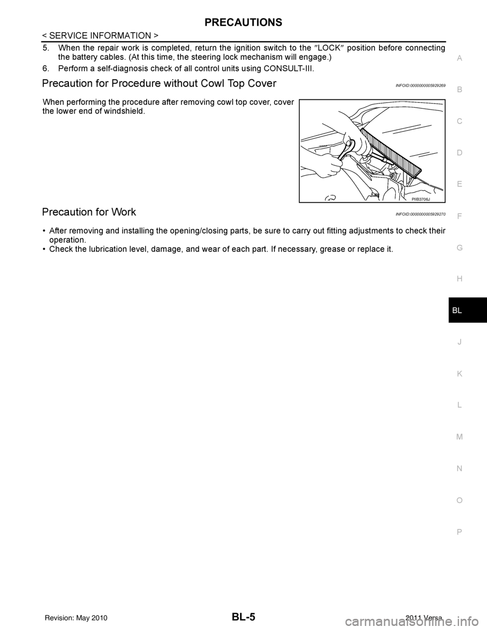
Precaution for Procedure without Cowl Top CoverINFOID:0000000005929269
When performing the procedure after removing cowl top cover, cover
the lower end of windshield.
Precaution for WorkINFOID:0000000005929270
• After removing and installing the opening/closing parts, be sure to carry out fitting adjustments to check their
operation.
• Check the lubrication level, damage, and wear of each part. If necessary, grease or replace it.
PIIB3706J
Revision: May 2010 2011 Versa
Page 531 of 3787

FRONT FENDERBL-21
< SERVICE INFORMATION >
C
DE
F
G H
J
K L
M A
B
BL
N
O P
FRONT FENDER
Removal and InstallationINFOID:0000000005929281
REMOVAL
1. Remove the headlamp assemblies. Refer to LT-25, "Removal and Installation".
2. Remove the cowl top cover (LH/RH). Refer to EI-24, "
Removal and Installation".
3. Remove the front fender protector. Refer to EI-26, "
Component".
4. Remove the bolt and the front fender.
CAUTION:
While removing use a shop cloth to pr otect the vechicle body from damage.
INSTALLATION
Installation is in the reverse order of removal.
CAUTION:
• After installing, apply touch-up paint on to the head of the front fender bolts.
• After installing, check front fender adjustment. Refer to BL-13, "
Fitting Adjustment" and BL-160, "Fit-
ting Adjustment".
1. Front fender 2 Bolt (LH 7 bolts required) (RH 8 bolts
required)
LIIA2657E
Revision: May 2010 2011 Versa
Page 778 of 3787

BL-268
< SERVICE INFORMATION >
BODY REPAIR
4. Front pillar inner reinforcement (RH&LH)
5. Lower dash reinforcement
6. 4th crossmember (RH&LH)
7. Front side member rear extension (RH&LH)
8. 3rd crossmember (RH&LH)
9. Front seat outer rear bracket (RH&LH)
10. Front seat inner rear bracket (RH&LH)
11. 2nd crossmember (RH&LH)
12. Front seat outer front bracket (RH&LH)
13. Front seat inner front bracket (RH&LH)
14. Fender bracket (RH&LH)
15. Strut housing assembly RH
16. Cowl top side upper (RH&LH)
17. Front strut housing (RH&LH)
18. Upper torque rod reinforcement
19. Closing plate assembly RH
20. Engine mount reinforcement
21. Strut tower front reinforcement RH
22. Front hoodledge lower RH
23. Frame bracket outer (RH&LH)
24. Front bumper support bracket (RH&LH)
25. Closing plate (RH&LH)
26. Front suspension rear bracket (RH&LH)
27. Front side member outrigger (RH&LH)
28. Front side member assembly (RH&LH)
29. Front side member (RH&LH)
30. Frame bracket (RH&LH)
31. Closing plate assembly LH
32. Hoodledge connector (RH&LH)
33. Radiator core side support (RH&LH)
34. Radiator core support upper (RH&LH)
35. Hoodledge upper (RH&LH)
36. Hoodledge reinforcement assembly (RH&LH)
37. Dash side (RH&LH)
38. Dash side assembly (RH& LH)
39. Front floor reinforcement (RH&LH)
40. Front floor front (RH&LH)
41. Front floor center
42. Rear seat crossmember
43. Rear center crossmember
44. Rear seat upper crossmember
45. Rear side member (RH&LH)
46. Sill inner extension (RH&LH)
47. Rear side member extension (RH&LH)
48. Rear side member assembly (RH & LH)
49. Rear floor front
50. Rear floor front assembly
51. Rear floor side (RH&LH)
52. Rear floor rear
Revision: May 20102011 Versa
Page 826 of 3787
BL-316
< SERVICE INFORMATION >
BODY REPAIR
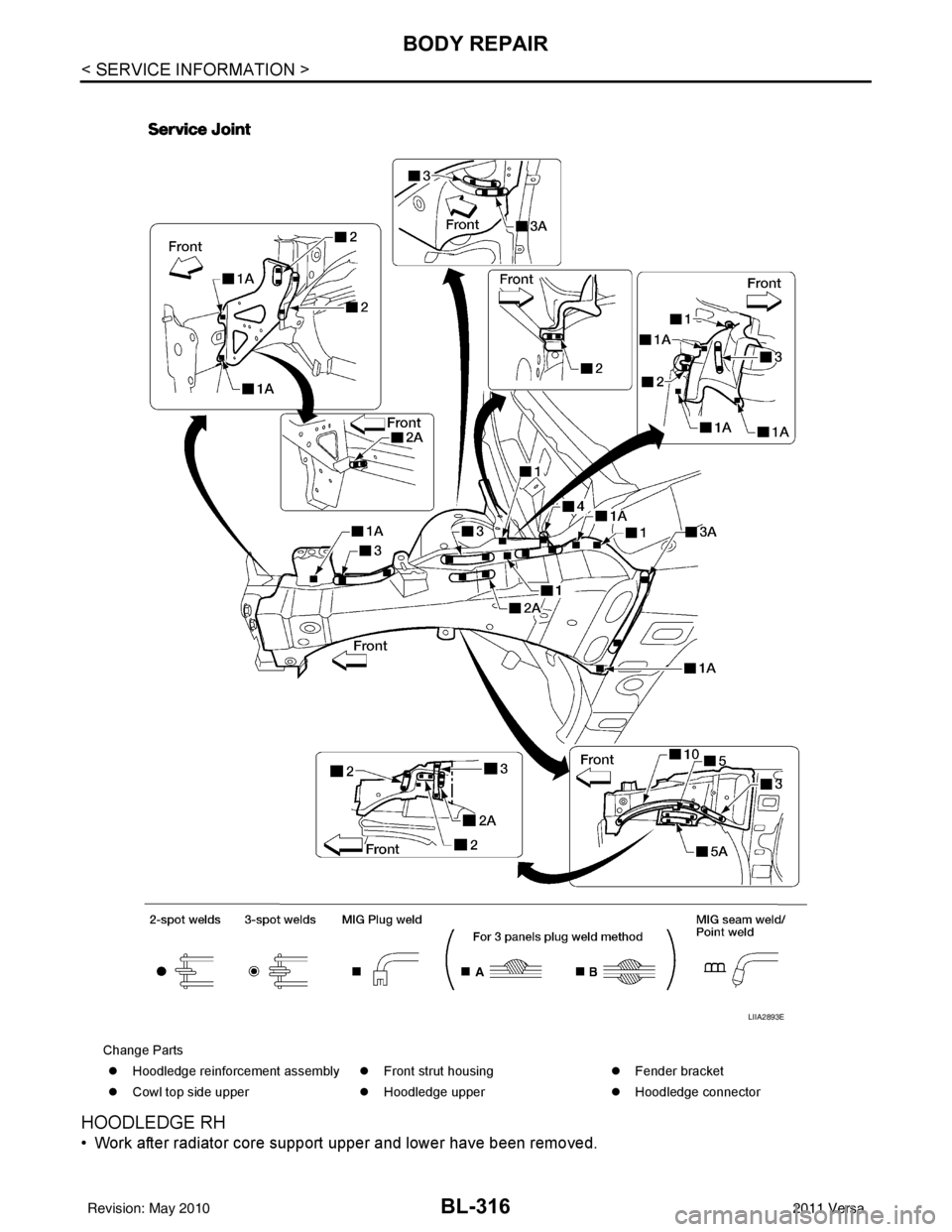
HOODLEDGE RH
• Work after radiator core support upper and lower have been removed.
Change Parts�z Hoodledge reinforcement assembly �zFront strut housing �zFender bracket
�z Cowl top side upper �zHoodledge upper �zHoodledge connector
LIIA2893E
Revision: May 2010 2011 Versa
Page 827 of 3787
BODY REPAIRBL-317
< SERVICE INFORMATION >
C
DE
F
G H
J
K L
M A
B
BL
N
O P
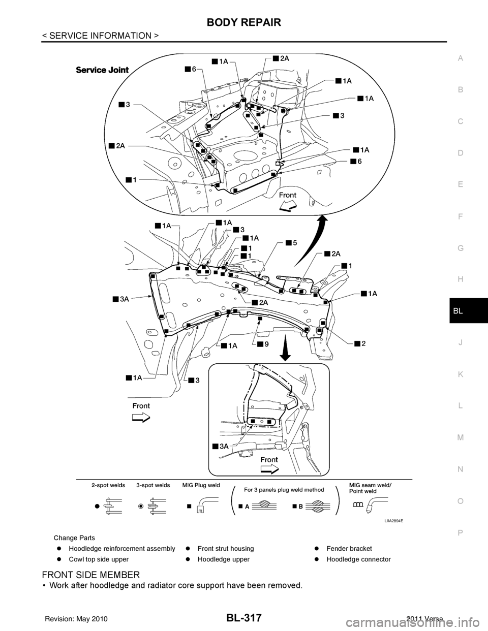
FRONT SIDE MEMBER
• Work after hoodledge and radiator core support have been removed.
Change Parts �z Hoodledge reinforcement assembly �zFront strut housing �zFender bracket
�z Cowl top side upper �zHoodledge upper �zHoodledge connector
LIIA2894E
Revision: May 2010 2011 Versa
Page 861 of 3787
BR-14
< SERVICE INFORMATION >
DUAL PROPORTIONING VALVE
DUAL PROPORTIONING VALVE
Removal and InstallationINFOID:0000000005928400
Removal
1. Remove the cowl top. Refer to EI-24, "Removal and Installation".
2. Disconnect brake lines from dual proportioning valve. • Mark brake lines for installation.
3. Remove dual proportioning valve bolt and dual proportioning valve.
4. Remove two bolts and bracket.
Installation
Installation is in the reverse order of removal.
• When installing brake lines to the dual proportioning valve, tighten to specifications. Refer to BR-11,
"Hydraulic Circuit".
InspectionINFOID:0000000005928401
CAUTION:
• Carefully monitor brake fluid level at master cylinder.
• Use the recommended new brake fluid. Refer to MA-14, "
Fluids and Lubricants".
• Be careful not to splash brake fluid on painted areas; it may cause paint damage. If brake fluid is
splashed on paint areas, wash it away with water immediately.
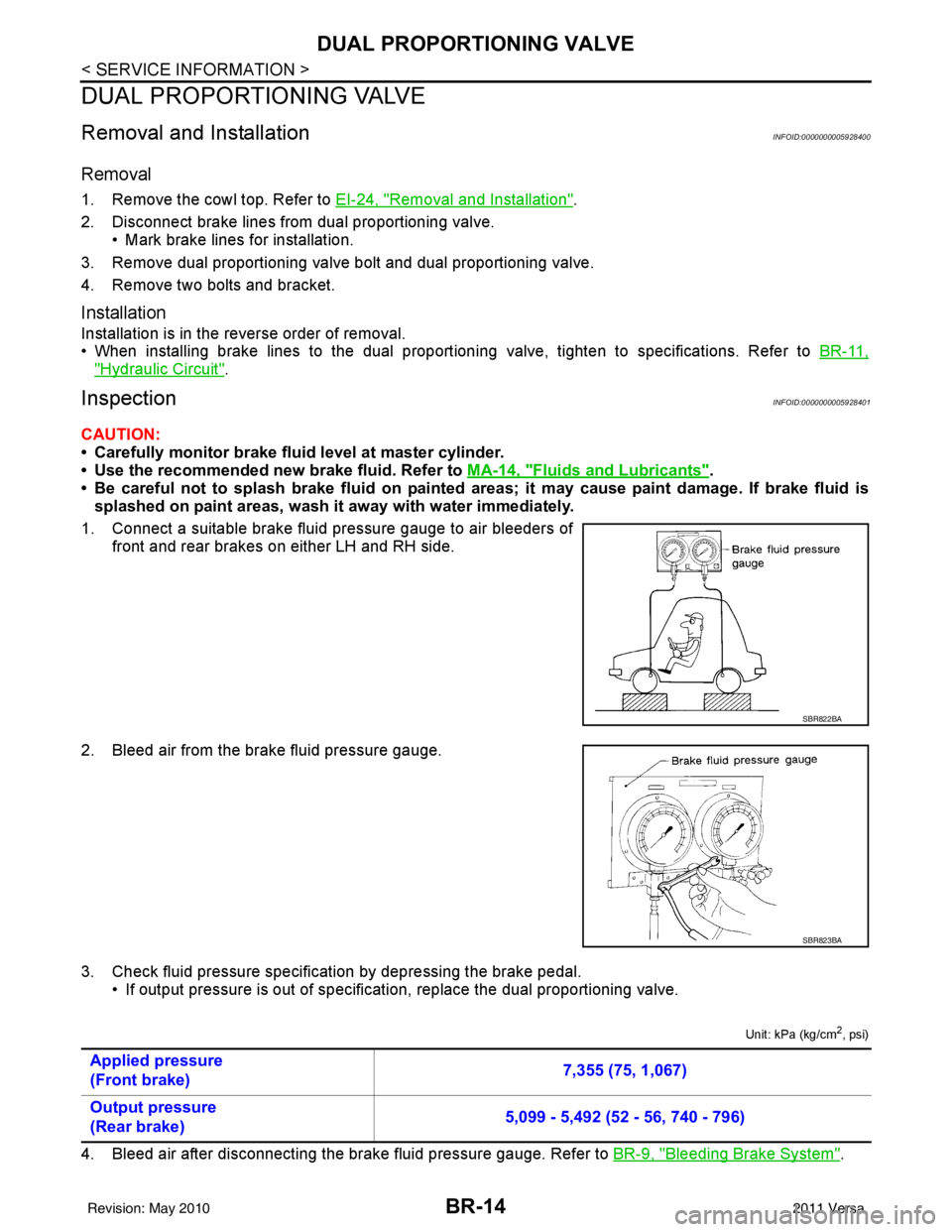
1. Connect a suitable brake fluid pressure gauge to air bleeders of front and rear brakes on either LH and RH side.
2. Bleed air from the brake fluid pressure gauge.
3. Check fluid pressure specific ation by depressing the brake pedal.
• If output pressure is out of specification, replace the dual proportioning valve.
Unit: kPa (kg/cm2, psi)
4. Bleed air after disconnecting the brake fluid pressure gauge. Refer to BR-9, "Bleeding Brake System".
SBR822BA
SBR823BA
Applied pressure
(Front brake) 7,355 (75, 1,067)
Output pressure
(Rear brake) 5,099 - 5,492 (52 - 56, 740 - 796)
Revision: May 2010
2011 Versa
Page 869 of 3787
BR-22
< SERVICE INFORMATION >
BRAKE BOOSTER
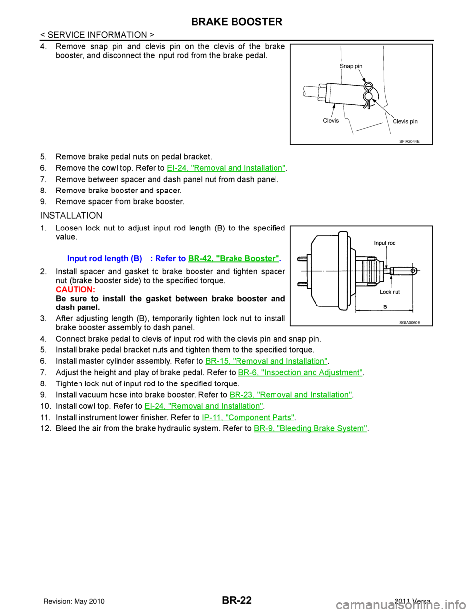
4. Remove snap pin and clevis pin on the clevis of the brakebooster, and disconnect the input rod from the brake pedal.
5. Remove brake pedal nuts on pedal bracket.
6. Remove the cowl top. Refer to EI-24, "
Removal and Installation".
7. Remove between spacer and dash panel nut from dash panel.
8. Remove brake booster and spacer.
9. Remove spacer from brake booster.
INSTALLATION
1. Loosen lock nut to adjust input rod length (B) to the specified value.
2. Install spacer and gasket to brake booster and tighten spacer nut (brake booster side) to the specified torque.
CAUTION:
Be sure to install the gasket between brake booster and
dash panel.
3. After adjusting length (B), temporarily tighten lock nut to install brake booster assembly to dash panel.
4. Connect brake pedal to clevis of input rod with the clevis pin and snap pin.
5. Install brake pedal bracket nuts and tighten them to the specified torque.
6. Install master cylinder assembly. Refer to BR-15, "
Removal and Installation".
7. Adjust the height and play of brake pedal. Refer to BR-6, "
Inspection and Adjustment".
8. Tighten lock nut of input rod to the specified torque.
9. Install vacuum hose into brake booster. Refer to BR-23, "
Removal and Installation".
10. Install cowl top. Refer to EI-24, "
Removal and Installation".
11. Install instrument lower finisher. Refer to IP-11, "
Component Parts".
12. Bleed the air from the brake hydraulic system. Refer to BR-9, "
Bleeding Brake System".
SFIA2044E
Input rod length (B) : Refer to BR-42, "Brake Booster".
SGIA0060E
Revision: May 2010 2011 Versa