Page 98 of 3787

TROUBLE DIAGNOSISAT-81
< SERVICE INFORMATION >
DE
F
G H
I
J
K L
M A
B
AT
N
O P
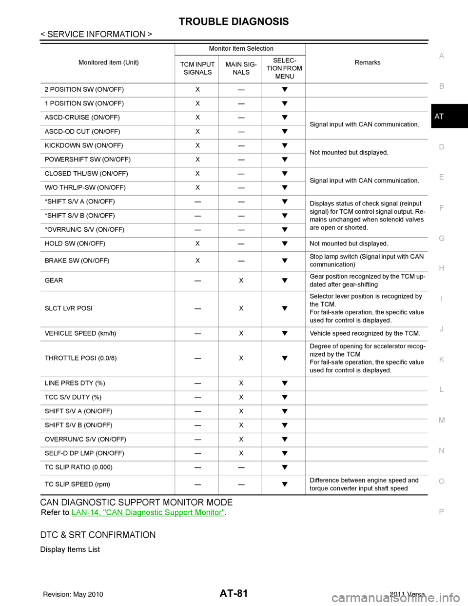
CAN DIAGNOSTIC SUPPORT MONITOR MODE
Refer to LAN-14, "CAN Diagnostic Support Monitor".
DTC & SRT CONFIRMATION
Display Items List
2 POSITION SW (ON/OFF) X—
1 POSITION SW (ON/OFF) X—
ASCD-CRUISE (ON/OFF) X—
Signal input with CAN communication.
ASCD-OD CUT (ON/OFF) X—
KICKDOWN SW (ON/OFF) X—
Not mounted but displayed.
POWERSHIFT SW (ON/OFF) X—
CLOSED THL/SW (ON/OFF) X—
Signal input with CAN communication.
W/O THRL/P-SW (ON/OFF) X—
*SHIFT S/V A (ON/OFF) ——
Displays status of check signal (reinput
signal) for TCM control signal output. Re-
mains unchanged when solenoid valves
are open or shorted.
*SHIFT S/V B (ON/OFF)
——
*OVRRUN/C S/V (ON/OFF) ——
HOLD SW (ON/OFF) X— Not mounted but displayed.
BRAKE SW (ON/OFF) X— Stop lamp switch (Signal input with CAN
communication)
GEAR —X Gear position recognized by the TCM up-
dated after gear-shifting
SLCT LVR POSI —X Selector lever position is recognized by
the TCM.
For fail-safe operation, the specific value
used for control is displayed.
VEHICLE SPEED (km/h) —X Vehicle speed reco gnized by the TCM.
THROTTLE POSI (0.0/8) —X Degree of opening for accelerator recog-
nized by the TCM
For fail-safe operation, the specific value
used for control is displayed.
LINE PRES DTY (%) —X
TCC S/V DUTY (%) —X
SHIFT S/V A (ON/OFF) —X
SHIFT S/V B (ON/OFF) —X
OVERRUN/C S/V (ON/OFF) —X
SELF-D DP LMP (ON/OFF) —X
TC SLIP RATIO (0.000) ——
TC SLIP SPEED (rpm) —— Difference between engine speed and
torque converter input shaft speed
Monitored item (Unit)
Monitor Item Selection
Remarks
TCM INPUT
SIGNALS MAIN SIG-
NALS SELEC-
TION FROM
MENU
Revision: May 2010 2011 Versa
Page 99 of 3787

AT-82
< SERVICE INFORMATION >
TROUBLE DIAGNOSIS
Diagnosis Procedure without CONSULT-III
INFOID:0000000005928106
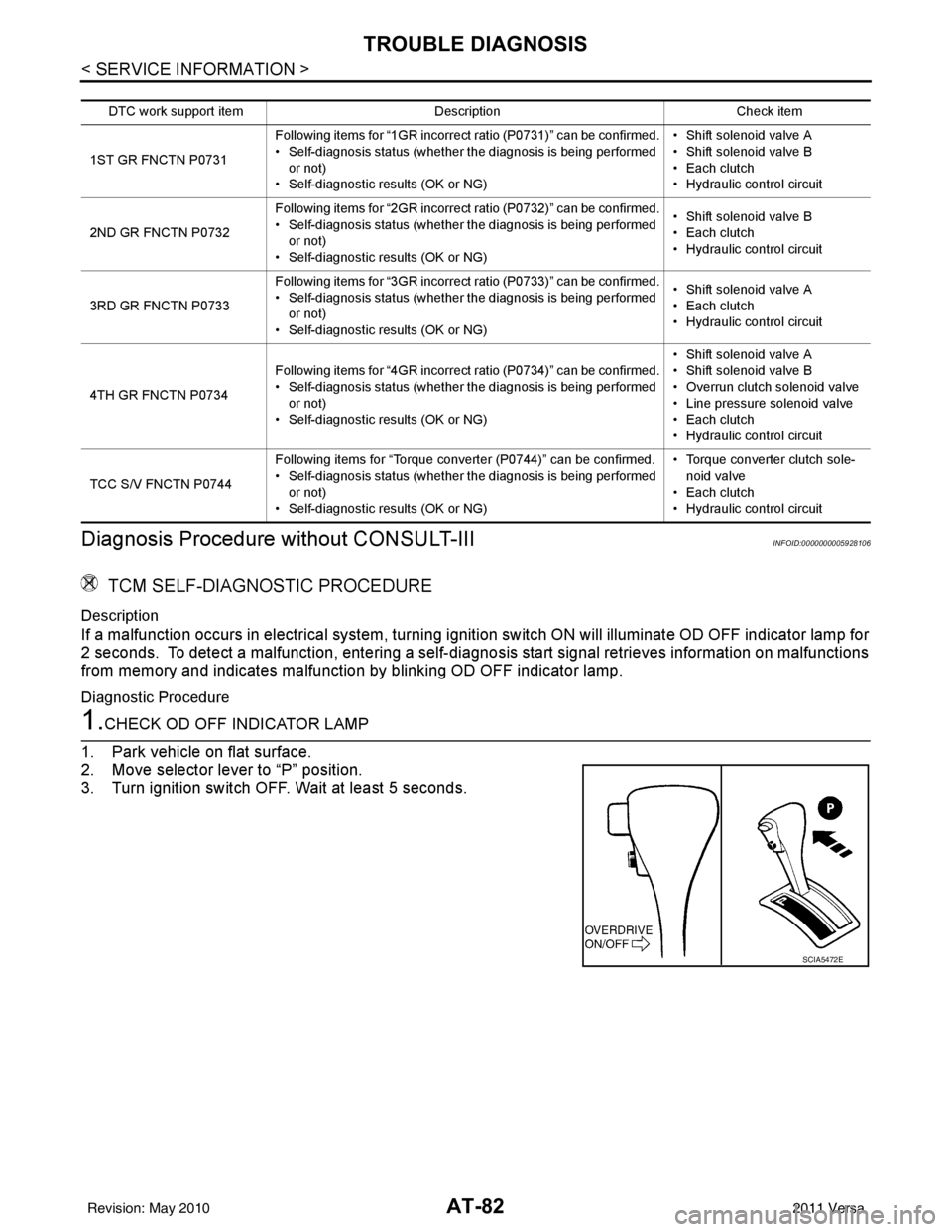
TCM SELF-DIAGNOSTIC PROCEDURE
Description
If a malfunction occurs in electrical system, turning ignition switch ON will illuminate OD OFF indicator lamp for
2 seconds. To detect a malfunction, entering a self-diagnosis start signal retrieves information on malfunctions
from memory and indicates malfunction by blinking OD OFF indicator lamp.
Diagnostic Procedure
1.CHECK OD OFF INDICATOR LAMP
1. Park vehicle on flat surface.
2. Move selector lever to “P” position.
3. Turn ignition switch OFF. Wait at least 5 seconds.
DTC work support item Description Check item
1ST GR FNCTN P0731 Following items for “1GR incorrect ratio (P0731)” can be confirmed.
• Self-diagnosis status (whether the diagnosis is being performed
or not)
• Self-diagnostic results (OK or NG) • Shift solenoid valve A
• Shift solenoid valve B
• Each clutch
•Hydraulic co
ntrol circuit
2ND GR FNCTN P0732 Following items for “2GR incorrect ratio (P0732)” can be confirmed.
• Self-diagnosis status (whether the diagnosis is being performed
or not)
• Self-diagnostic results (OK or NG) • Shift solenoid valve B
• Each clutch
•Hydraulic co
ntrol circuit
3RD GR FNCTN P0733 Following items for “3GR incorrect ratio (P0733)” can be confirmed.
• Self-diagnosis status (whether the diagnosis is being performed
or not)
• Self-diagnostic results (OK or NG) • Shift solenoid valve A
• Each clutch
•Hydraulic co
ntrol circuit
4TH GR FNCTN P0734 Following items for “4GR incorrect ratio (P0734)” can be confirmed.
• Self-diagnosis status (whether the diagnosis is being performed
or not)
• Self-diagnostic results (OK or NG) • Shift solenoid valve A
• Shift solenoid valve B
• Overrun clutch solenoid valve
• Line pressure solenoid valve
• Each clutch
•Hydraulic co
ntrol circuit
TCC S/V FNCTN P0744 Following items for “Torque converter (P0744)” can be confirmed.
• Self-diagnosis status (whether the diagnosis is being performed
or not)
• Self-diagnostic results (OK or NG) • Torque converter clutch sole-
noid valve
• Each clutch
•Hydraulic co ntrol circuit
SCIA5472E
Revision: May 2010 2011 Versa
Page 274 of 3787
DISASSEMBLYAT-257
< SERVICE INFORMATION >
DE
F
G H
I
J
K L
M A
B
AT
N
O P
DISASSEMBLY
DisassemblyINFOID:0000000005928289
1. Drain ATF through drain hole.
2. Remove drain plug gasket from drain plug.
3. Remove torque converter.
4. Check torque converter one-way clutch using check tool as shown.
a. Insert check tool into groove of bearing support built into one- way clutch outer race.
b. When fixing bearing support with check tool, rotate one-way clutch spline using screwdriver.
c. Check that inner race rotates clockwise only. If not, replace torque converter assembly.
SCIA0003E
SAT008D
SAT009D
Revision: May 2010 2011 Versa
Page 299 of 3787
AT-282
< SERVICE INFORMATION >
REPAIR FOR COMPONENT PARTS
DISASSEMBLY
Place control valve assembly with control valve upper body (1) side
down. Remove bolts (A) to (G), reamer bolts (F), nuts and support
plates (4) according to the following procedures. Separate control
valve upper body (1), control valve inter body (2) and control valve
lower body (3).
1. Pilot filter2. Control valve upper body 3. Steel ball
4. Separating plate 5. Control valve inter body 6. Steel ball
7. Support plate 8. Separating plate9. Control valve lower body
10. Line pressure relief valve spring 11. Check ball 12. Torque converter pressure
holding spring
13. Solenoid valve assembly 14. Terminal body 15. O-ring
16. O-ring 17. O-ring18. Oil strainer
SCIA8407J
SCIA7058E
Revision: May 2010 2011 Versa
Page 301 of 3787
AT-284
< SERVICE INFORMATION >
REPAIR FOR COMPONENT PARTS
5. Remove control valve lower body (1) from control valve interbody (2).
(3): Control valve upper body
6. Turn over control valve lower body (1).
7. Remove bolts (E), support plates (2) and separating plate (3) from control valve lower body (1).
8. Remove check balls (1), line pressure relief valve springs (2) and torque converter pressure holding spring (3) from control
valve lower body (4).
CAUTION:
Be careful not to lose check ba lls (1), line pressure relief
valve springs (2) and torque converter pressure holding
spring (3).
9. Remove control valve inter body from control valve upper body.
10. Remove pilot filter (1) from control valve upper body (2).
11. Remove separating plate from control valve upper body (2).
SCIA7181E
SCIA7009E
SCIA6491J
SCIA4977E
SCIA7011E
Revision: May 2010 2011 Versa
Page 305 of 3787
AT-288
< SERVICE INFORMATION >
REPAIR FOR COMPONENT PARTS
f. Install check balls (1), line pressure relief valve springs (2) andtorque converter pressure holding spring (3) in their proper posi-
tions in control valve lower body (4).
g. Install bolts (E) from bottom of control valve lower body (1). Using bolts (E) as guides, install separating plate (2) as a set.
h. Install support plates (3) on control valve lower body (1).
i. Install control valve lower body (1) on control valve inter body (2) using reamer bolts (F) as guides, and tighten reamer bolts (F)
slightly.
2. Install O-rings on solenoid valves and terminal body.
SCIA6491J
SCIA7013E
SCIA7014E
SCIA7180E
Revision: May 2010 2011 Versa
Page 306 of 3787
REPAIR FOR COMPONENT PARTSAT-289
< SERVICE INFORMATION >
DE
F
G H
I
J
K L
M A
B
AT
N
O P
3. Install and tighten bolts. (1): Control valve upper body
(2): Control valve inter body
(3): Control valve lower body
(4): Support plate
Bolt length, number and location:
*: Reamer bolt and nut.
a. Install and tighten bolts (B) to the specified torque.
b. Install solenoid valve assembly (1) on control valve assembly.
c. Tighten bolts (A), (C) and (G) to the specified torque.
SCIA7058E
Bolt symbol ABC D EF*G
Bolt length “ ” [mm (in)] 13.5
(0.531) 58.0
(2.283) 40.0
(1.575) 66.0
(2.598) 33.0
(1.299) 78.0
(3.071) 18.0
(0.709)
Number of bolts 63 611 221
Tightening torque
[N·m (kg-m, in-lb)] 8.6 (0.88, 76)5.0
(0.51, 44) 8.6 (0.88, 76)
ATL0032D
SCIA7008E
Revision: May 2010
2011 Versa
Page 361 of 3787

AT-344
< SERVICE INFORMATION >
ASSEMBLY
ASSEMBLY
Assembly (1)INFOID:0000000005928303
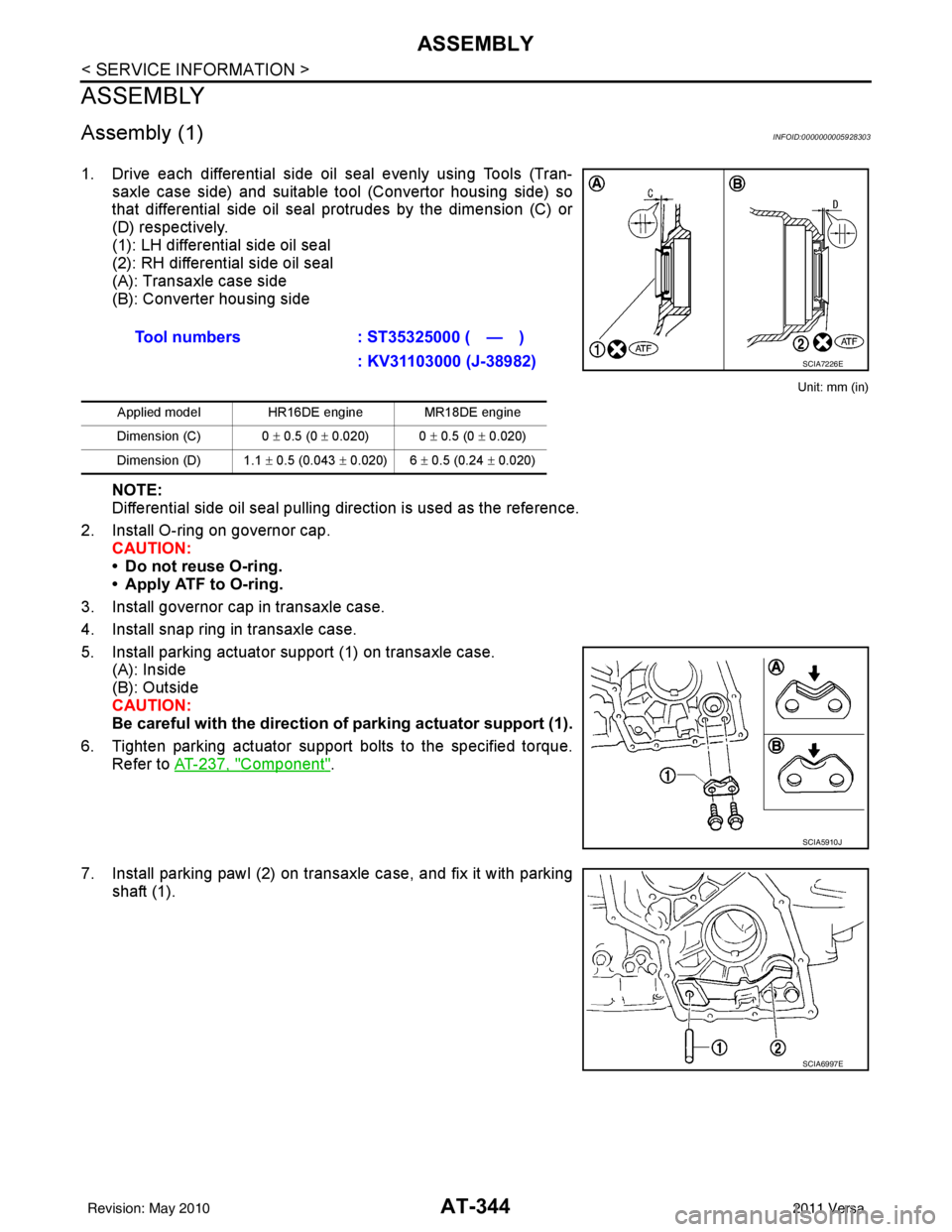
1. Drive each differential side oil seal evenly using Tools (Tran-saxle case side) and suitable tool (Convertor housing side) so
that differential side oil seal protrudes by the dimension (C) or
(D) respectively.
(1): LH differential side oil seal
(2): RH differential side oil seal
(A): Transaxle case side
(B): Converter housing side
Unit: mm (in)
NOTE:
Differential side oil seal pulling direction is used as the reference.
2. Install O-ring on governor cap. CAUTION:
• Do not reuse O-ring.
• Apply ATF to O-ring.
3. Install governor cap in transaxle case.
4. Install snap ring in transaxle case.
5. Install parking actuator support (1) on transaxle case. (A): Inside
(B): Outside
CAUTION:
Be careful with the direction of parking actuator support (1).
6. Tighten parking actuator support bolts to the specified torque. Refer to AT-237, "
Component".
7. Install parking pawl (2) on transaxle case, and fix it with parking shaft (1).Tool numbers
: ST35325000 ( — )
: KV31103000 (J-38982)
Applied model HR16DE engine MR18DE engine
Dimension (C) 0 ± 0.5 (0 ± 0.020) 0 ± 0.5 (0 ± 0.020)
Dimension (D) 1.1 ± 0.5 (0.043 ± 0.020) 6 ± 0.5 (0.24 ± 0.020)
SCIA7226E
SCIA5910J
SCIA6997E
Revision: May 2010 2011 Versa