Page 2649 of 3787

FRONT WHEEL HUB AND KNUCKLEFAX-7
< SERVICE INFORMATION >
CEF
G H
I
J
K L
M A
B
FA X
N
O P
2. Without disassembling the hydraulic lines, remove the torque member bolts using power tool. Then repo- sition the torque member and brake caliper assembly aside with wire. Refer to BR-25
.
CAUTION:
Do not depress brake pedal while brake caliper is removed.
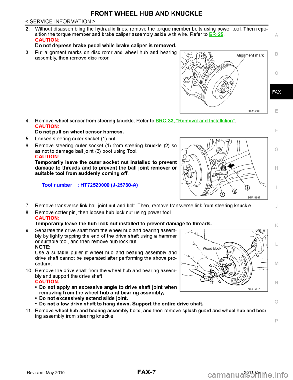
3. Put alignment marks on disc rotor and wheel hub and bearing assembly, then remove disc rotor.
4. Remove wheel sensor from steering knuckle. Refer to BRC-33, "
Removal and Installation".
CAUTION:
Do not pull on wheel sensor harness.
5. Loosen steering outer socket (1) nut.
6. Remove steering outer socket (1) from steering knuckle (2) so as not to damage ball joint (3) boot using Tool.
CAUTION:
Temporarily leave the outer socket nut installed to prevent
damage to threads and to prevent the ball joint remover or
suitable tool from suddenly coming off.
7. Remove transverse link ball joint nut and bolt. Then, remove transverse link from steering knuckle.
8. Remove cotter pin, then loosen hub lock nut using power tool. CAUTION:
Temporarily leave the hub lock nut inst alled to prevent damage to threads.
9. Separate the drive shaft from the wheel hub and bearing assem- bly by lightly tapping the end of the drive shaft using a hammer
or suitable tool, and then remove hub lock nut.
NOTE:
Use a suitable puller if wheel hub and bearing assembly and
drive shaft cannot be separated after performing the above pro-
cedure.
10. Remove the drive shaft from the wheel hub and bearing assem- bly and support the drive shaft.
CAUTION:
• Do not apply an excessive angle to drive shaft joint when
removing from the wheel hub and bearing assembly,
• Do not excessively extend slide joint.
• Do not allow drive shaft to hang do wn. Support the entire drive shaft.
11. Remove wheel hub and bearing assembly bolts, and then remove splash guard and wheel hub and bear- ing assembly from steering knuckle.
SDIA1480E
Tool number : HT72520000 (J-25730-A)
SGIA1298E
SDIA1821E
Revision: May 2010 2011 Versa
Page 2680 of 3787

FUEL TANKFL-13
< SERVICE INFORMATION >
C
DE
F
G H
I
J
K L
M A
FL
NP
O
EVAP Canister
1. Check the connection for damage or any foreign materials.
2. Align the connector with the tube, then insert the c
onnector straight into the tube until a “click” sound is
heard.
3. After connecting, make sure that the connection is secure. • Pull the tube and the connector to make sure they are securely connected.
Fuel Tank Bands
Install the fuel tank bands in the proper position by referring to the identification stamp mark “R” and “L” on the
end
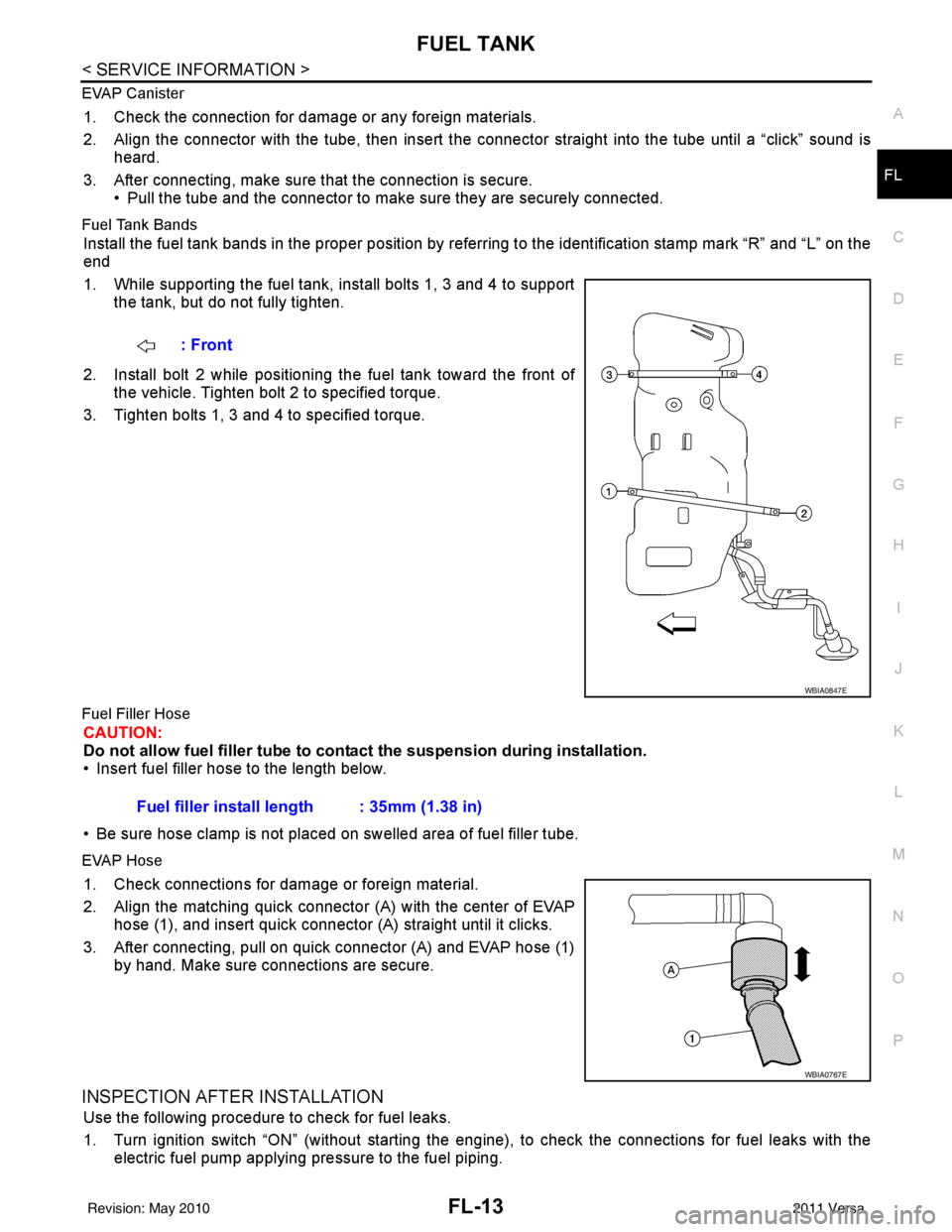
1. While supporting the fuel tank, install bolts 1, 3 and 4 to supportthe tank, but do not fully tighten.
2. Install bolt 2 while positioning the fuel tank toward the front of the vehicle. Tighten bolt 2 to specified torque.
3. Tighten bolts 1, 3 and 4 to specified torque.
Fuel Filler Hose
CAUTION:
Do not allow fuel filler tube to cont act the suspension during installation.
• Insert fuel filler hose to the length below.
• Be sure hose clamp is not placed on swelled area of fuel filler tube.
EVAP Hose
1. Check connections for damage or foreign material.
2. Align the matching quick connector (A) with the center of EVAP
hose (1), and insert quick connector (A) straight until it clicks.
3. After connecting, pull on quick connector (A) and EVAP hose (1) by hand. Make sure connections are secure.
INSPECTION AFTER INSTALLATION
Use the following procedure to check for fuel leaks.
1. Turn ignition switch “ON” (without starting the engi ne), to check the connections for fuel leaks with the
electric fuel pump applying pressure to the fuel piping. : Front
WBIA0847E
Fuel filler install length : 35mm (1.38 in)
WBIA0767E
Revision: May 2010
2011 Versa
Page 2859 of 3787
![NISSAN TIIDA 2011 Service Repair Manual TROUBLE DIAGNOSISLAN-13
< SERVICE INFORMATION > [CAN FUNDAMENTAL]
C
D
E
F
G H
I
J
L
M A
B
LAN
N
O P
Example: CAN-H, CAN-L Harness Short Circuit
CAN Diagnosis with CONSULT-IIIINFOID:0000000005928521
CA NISSAN TIIDA 2011 Service Repair Manual TROUBLE DIAGNOSISLAN-13
< SERVICE INFORMATION > [CAN FUNDAMENTAL]
C
D
E
F
G H
I
J
L
M A
B
LAN
N
O P
Example: CAN-H, CAN-L Harness Short Circuit
CAN Diagnosis with CONSULT-IIIINFOID:0000000005928521
CA](/manual-img/5/57396/w960_57396-2858.png)
TROUBLE DIAGNOSISLAN-13
< SERVICE INFORMATION > [CAN FUNDAMENTAL]
C
D
E
F
G H
I
J
L
M A
B
LAN
N
O P
Example: CAN-H, CAN-L Harness Short Circuit
CAN Diagnosis with CONSULT-IIIINFOID:0000000005928521
CAN diagnosis on CONSULT-III extracts the root
cause by receiving the following information.
• Response to the system call
• Control unit diagnosis information
• Self-diagnosis
• CAN diagnostic support monitor
SKIB8741E
Unit name Symptom
ECM • Engine torque limiting is affected, and shift harshness increases.
• Engine speed drops.
BCM • Reverse warning chime does not sound.
• The front wiper moves under continuous operation mode even though the front
wiper switch being in the intermittent position.
• The room lamp does not turn ON.
• The engine does not start (if an error or malfunction occurs while turning the igni- tion switch OFF.)
• The steering lock does not release (if an error or malfunction occurs while turning the ignition switch OFF.)
EPS control unit The steering effort increases.
Combination meter • The tachometer and the speedometer do not move.
• Warning lamps turn ON.
• Indicator lamps do not turn ON.
ABS actuator and electric unit (control unit) Normal operation.
TCM No impact on operation.
IPDM E/R When the ignition switch is ON,
• The headlamps (Lo) turn ON.
• The cooling fan continues to rotate.
Revision: May 2010
2011 Versa
Page 3695 of 3787
![NISSAN TIIDA 2011 Service Repair Manual STC-8
< SYSTEM DESCRIPTION >[EPS]
DIAGNOSIS SYSTEM (EPS CONTROL UNIT)
DIAGNOSIS SYSTEM
(EPS CONTROL UNIT)
CONSULT-III FunctionINFOID:0000000005931228
FUNCTION
CONSULT-III can display each diagnostic NISSAN TIIDA 2011 Service Repair Manual STC-8
< SYSTEM DESCRIPTION >[EPS]
DIAGNOSIS SYSTEM (EPS CONTROL UNIT)
DIAGNOSIS SYSTEM
(EPS CONTROL UNIT)
CONSULT-III FunctionINFOID:0000000005931228
FUNCTION
CONSULT-III can display each diagnostic](/manual-img/5/57396/w960_57396-3694.png)
STC-8
< SYSTEM DESCRIPTION >[EPS]
DIAGNOSIS SYSTEM (EPS CONTROL UNIT)
DIAGNOSIS SYSTEM
(EPS CONTROL UNIT)
CONSULT-III FunctionINFOID:0000000005931228
FUNCTION
CONSULT-III can display each diagnostic item us ing the diagnostic test modes shown following.
ECU IDENTIFICATION
Displays the part number stored in the control unit.
SELF-DIAG RESULTS MODE
Display Item List
Refer to STC-24, "DTC Index".
CAUTION:
If “CAN COMM CIRCUIT [U1000]” is disp layed with other DTCs, first perform the trouble diagnosis for
CAN communication line.
DATA MONITOR MODE
Display Item List
*1: Almost in accordance with the value of MOTOR SIG. It is not a malfunction though these values are not accorded when steerin g
quickly.
*2: It is not a malfunction, though it might not be corresponding just after ignition switch in turned ON. Diagnostic test mode
Function
ECU identification Steering column assembly number can be read.
Self diagnostic result Self-diagnostic results can be read and erased quickly.
CAN diag support MNTR The results of transmit/receive diagnosis of CAN communication can be read.
Data monitor Input/Output data in the EPS control unit can be read.
Monitor item (Unit) Remarks
BATTERY VOLT (V) Displays the power supply voltage for EPS control unit.
TORQUE SENSOR (Nm) Displays steering wheel turning force detected by torque sensor.
MOTOR CURRENT (A) Displays the current value consumed by EPS motor.
MOTOR SIG (A)
*1Displays the current commanded value to EPS motor.
VEHICLE SPEED (km/h) or (MPH)
*2Vehicle speed is displayed from vehicle speed signal via CAN communication.
WARNING LAMP (On/Off) EPS warning lamp control status is displayed.
ENGINE STATUS (Stop/Run) Engine speed is displayed from engine status signal via CAN communication.
Revision: May 2010 2011 Versa
Page:
< prev 1-8 9-16 17-24