2011 NISSAN TIIDA Park light fuse
[x] Cancel search: Park light fusePage 1282 of 3787
WARNING CHIMEDI-43
< SERVICE INFORMATION >
C
DE
F
G H
I
J
L
M A
B
DI
N
O P
WARNING CHIME
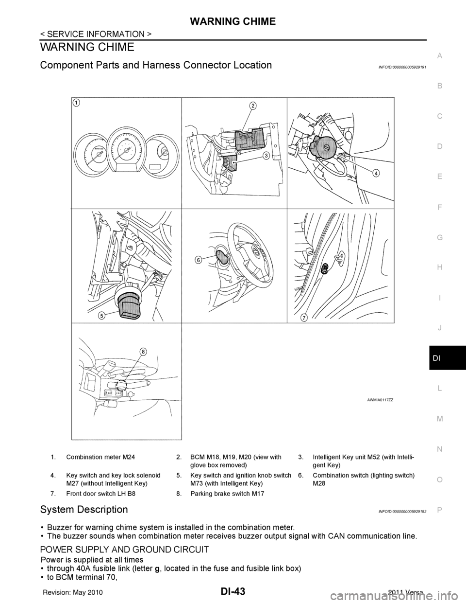
Component Parts and Har ness Connector LocationINFOID:0000000005929191
System DescriptionINFOID:0000000005929192
• Buzzer for warning chime system is installed in the combination meter.
• The buzzer sounds when combination meter receives buzzer output signal with CAN communication line.
POWER SUPPLY AND GROUND CIRCUIT
Power is supplied at all times
• through 40A fusible link (letter g, located in the fuse and fusible link box)
• to BCM terminal 70,
1. Combination meter M24 2. BCM M18, M19, M20 (view with
glove box removed) 3. Intelligent Key unit M52 (with Intelli-
gent Key)
4. Key switch and key lock solenoid M27 (without Intelligent Key) 5. Key switch and ignition knob switch
M73 (with Intelligent Key) 6. Combination switch (lighting switch)
M28
7. Front door switch LH B8 8. Parking brake switch M17
AWMIA0117ZZ
Revision: May 2010 2011 Versa
Page 3059 of 3787
HEADLAMP (FOR CANADA) - DAYTIME LIGHT SYSTEM -
LT-27
< SERVICE INFORMATION >
C
D E
F
G H
I
J
L
M A
B
LT
N
O P
HEADLAMP (FOR CANADA) - DAYTIME LIGHT SYSTEM -
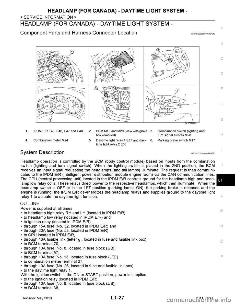
Component Parts and Harness Connector LocationINFOID:0000000005929049
System DescriptionINFOID:0000000005929050
Headlamp operation is controlled by the BCM (body c ontrol module) based on inputs from the combination
switch (lighting and turn signal switch). When the light ing switch is placed in the 2ND position, the BCM
receives an input signal requesting the headlamps (and ta il lamps) illuminate. The request is then communi-
cated to the IPDM E/R (intelligent power distribution module engine room) via the CAN communication lines.
The CPU (central processing unit) located in t he IPDM E/R controls ground for the headlamp high and head-
lamp low relay coils. These relays direct power to the respective headlamps, which then illuminate. When the
headlamp switch is OFF or in the 1ST position (parking lamps ON), the parking brake is released and the
engine is running, the IPDM E/R de-energizes the headlamp relays and supplies ground to the daytime light
relay 1 to actuate the daytime light function.
OUTLINE
Power is supplied at all times
• to headlamp high relay RH and LH (located in IPDM E/R)
• to headlamp low relay (located in IPDM E/R) and
• to ignition relay (located in IPDM E/R)
• through 15A fuse (No. 52, located in IPDM E/R) and
• through 20A fuse (No. 53, located in IPDM E/R)
• to CPU located in IPDM E/R,
• through 40A fusible link (letter g , located in fuse and fusible link box)
• to BCM terminal 70,
• through 10A fuse [No. 8, located in fuse block (J/B)]
• to BCM terminal 57,
• through 10A fuse [No. 13, located in fuse block (J/B)]
• to combination meter terminal 27,
• through 10A fuse (No. 26, located in fuse and fusible link box)
• to the daytime light relay 1.
With the ignition switch in the ON or START position, power is supplied
• to the ignition relay (located in IPDM E/R),
• through 10A fuse [No. 6, located in fuse block (J/B)]
• to BCM terminal 38,
1. IPDM E/R E43, E46, E47 and E48 2. BCM M18 and M20 (view with glove
box removed)3. Combination switch (lighting and
turn signal switch) M28
4. Combination meter M24 5. Daytime light relay 1 E37 and day-
time light relay 2 E38 6. Parking brake switch M17
WKIA5555E
Revision: May 2010
2011 Versa
Page 3060 of 3787
![NISSAN TIIDA 2011 Service Repair Manual LT-28
< SERVICE INFORMATION >
HEADLAMP (FOR CANADA) - DAYTIME LIGHT SYSTEM -
• through 10A fuse [No. 3, located in fuse block (J/B)]
• to combination meter terminal 28.
With the ignition switch in](/manual-img/5/57396/w960_57396-3059.png "NISSAN TIIDA 2011 Service Repair Manual LT-28
< SERVICE INFORMATION >
HEADLAMP (FOR CANADA) - DAYTIME LIGHT SYSTEM -
• through 10A fuse [No. 3, located in fuse block (J/B)]
• to combination meter terminal 28.
With the ignition switch in")
LT-28
< SERVICE INFORMATION >
HEADLAMP (FOR CANADA) - DAYTIME LIGHT SYSTEM -
• through 10A fuse [No. 3, located in fuse block (J/B)]
• to combination meter terminal 28.
With the ignition switch in the ACC or ON position, power is supplied
• through 10A fuse [No. 20, located in fuse block (J/B)]
• to BCM terminal 11.
Ground is supplied
• to BCM terminal 67 and
• to combination meter terminals 21, 22 and 23
• through grounds M57 and M61,
• to IPDM E/R terminals 39 and 59
• through grounds E15 and E24,
HEADLAMP OPERATION
Low Beam Operation
With the lighting switch in 2ND position, the BCM re ceives an input signal requesting the headlamps to illumi-
nate. This input signal is communicated to the IPDM E/R via the CAN communication lines. The CPU located
in the IPDM E/R controls the headlamp low re lay coil, which when energized, directs power
• through 15A fuse (No. 41, located in IPDM E/R)
• through IPDM E/R terminal 54
• to daytime light relay 2 terminals 1 and 5 (energizing the relay),
• through daytime light relay 2 terminal 3
• to front combination lamp RH terminal 3, and
• through 15A fuse (No. 40, located in IPDM E/R)
• through IPDM E/R terminal 52
• to front combination lamp LH terminal 3.
Ground is supplied
• to front combination lamp LH terminal 2
• through grounds E15 and E24,
• to headlamp RH terminal 2 via
• daytime light relay 1 terminals 3 and 4
• through grounds E15 and E24.
With power and ground supplied, low beam headlamps illuminate.
High Beam/Flash-to-Pass Operation
With the lighting switch in 2ND position and high beam s witch in the HIGH position, the BCM receives input
signal requesting the headlamp high beams to illuminate. The flash-to-pass feature can be used any time and
also sends a signal to the BCM. This input signal is communicated to the IPDM E/R and the combination
meter via the CAN communication lines. The CPU locat ed in the IPDM E/R controls the headlamp high relay
coil, which when energized, directs power
• through 10A fuse (No. 34, located in IPDM E/R)
• through IPDM E/R terminal 56
• to front combination lamp RH terminal 1, and
• through 10A fuse (No. 35, located in IPDM E/R)
• through IPDM E/R terminal 55
• to front combination lamp LH terminal 1.
Ground is supplied
• to front combination lamp LH terminal 2
• through grounds E15 and E24, and
• to front combination lamp RH terminal 2 via
• daytime light relay 1 terminals 3 and 4
• through grounds E15 and E24.
With power and ground supplied, the high beam headlamps illuminate.
The BCM sends a signal to the combination meter requesting the high beam indicator lamp to turn ON.
Daytime Light System Operation
With the lighting switch in the OFF or 1ST position (parking lamps ON), the BCM receives inputs requesting
the headlights off. If the parking brake is released and the engine is running, the BCM then sends a signal, via
the CAN communication lines, requesting the IPDM E/R to activate the daytime light system. The CPU located
in the IPDM E/R controls the daytime light relay 1 coil, which when energized, directs power
• from daytime light relay 1 terminal 3
• to front combination lamp RH terminal 2,
• through front combination lamp RH high beam terminal 1
Revision: May 2010 2011 Versa
Page 3106 of 3787
LT-74
< SERVICE INFORMATION >
PARKING, LICENSE PLATE AND TAIL LAMPS
PARKING, LICENSE PLATE AND TAIL LAMPS
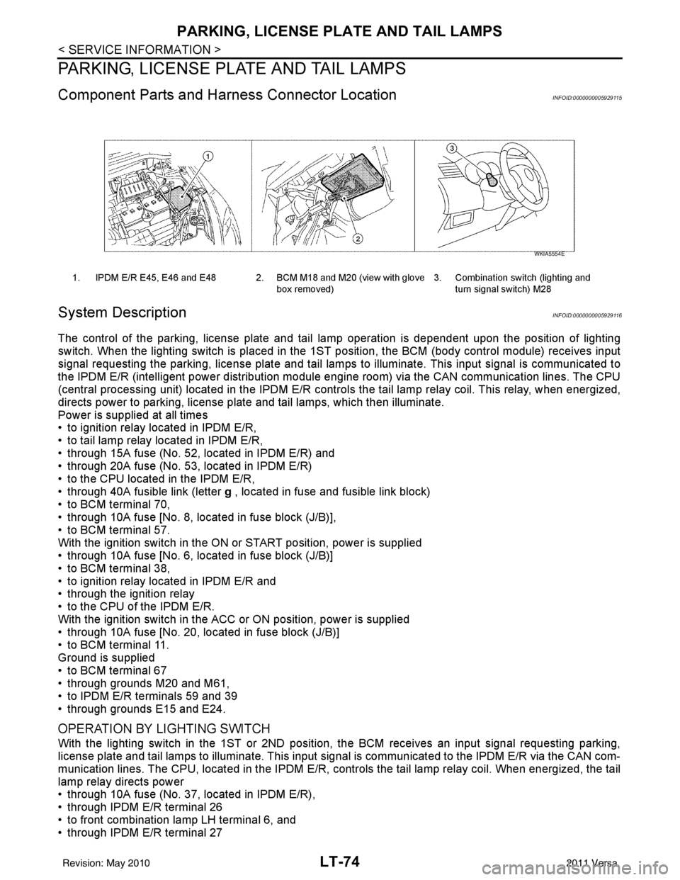
Component Parts and Harness Connector LocationINFOID:0000000005929115
System DescriptionINFOID:0000000005929116
The control of the parking, license plate and tail lamp operation is dependent upon the position of lighting
switch. When the lighting switch is placed in the 1ST position, the BCM (body cont rol module) receives input
signal requesting the parking, license plate and tail lamps to illuminate. This input signal is communicated to
the IPDM E/R (intelligent power distribution module engine room) via the CAN communication lines. The CPU
(central processing unit) located in the IPDM E/R contro ls the tail lamp relay coil. This relay, when energized,
directs power to parking, license plate and tail lamps, which then illuminate.
Power is supplied at all times
• to ignition relay located in IPDM E/R,
• to tail lamp relay located in IPDM E/R,
• through 15A fuse (No. 52, located in IPDM E/R) and
• through 20A fuse (No. 53, located in IPDM E/R)
• to the CPU located in the IPDM E/R,
• through 40A fusible link (letter g , located in fuse and fusible link block)
• to BCM terminal 70,
• through 10A fuse [No. 8, located in fuse block (J/B)],
• to BCM terminal 57.
With the ignition switch in the ON or START position, power is supplied
• through 10A fuse [No. 6, located in fuse block (J/B)]
• to BCM terminal 38,
• to ignition relay located in IPDM E/R and
• through the ignition relay
• to the CPU of the IPDM E/R.
With the ignition switch in the ACC or ON position, power is supplied
• through 10A fuse [No. 20, located in fuse block (J/B)]
• to BCM terminal 11.
Ground is supplied
• to BCM terminal 67
• through grounds M20 and M61,
• to IPDM E/R terminals 59 and 39
• through grounds E15 and E24.
OPERATION BY LIGHTING SWITCH
With the lighting switch in the 1ST or 2ND position, the BCM receives an input signal requesting parking,
license plate and tail lamps to illuminate. This input signal is communicated to the IPDM E/R via the CAN com-
munication lines. The CPU, located in the IPDM E/R, controls the tail lamp relay coil. When energized, the tail
lamp relay directs power
• through 10A fuse (No. 37, located in IPDM E/R),
• through IPDM E/R terminal 26
• to front combination lamp LH terminal 6, and
• through IPDM E/R terminal 27
1. IPDM E/R E45, E46 and E48 2. BCM M18 and M20 (view with glove
box removed)3. Combination switch (lighting and
turn signal switch) M28
WKIA5554E
Revision: May 2010 2011 Versa
Page 3113 of 3787
PARKING, LICENSE PLATE AND TAIL LAMPS
LT-81
< SERVICE INFORMATION >
C
D E
F
G H
I
J
L
M A
B
LT
N
O P
How to Proceed with Trouble DiagnosisINFOID:0000000005929122
1. Confirm the symptom or customer complaint.
2. Understand operation description and function description. Refer to LT-74, "
System Description" .
3. Perform the preliminary check. Refer to LT-81, "
Preliminary Check" .
4. Check symptom and repair or replace the cause of the malfunction.
5. Do the parking, license plate and tail lamps operate normally? If YES, GO TO 6. If NO, GO TO 4.
6. Inspection End.
Preliminary CheckINFOID:0000000005929123
CHECK POWER SUPPLY AND GROUND CIRCUIT FOR BCM
Refer to BCS-16, "BCM Power Supply and Ground Circuit Inspection" .
CHECK POWER SUPPLY AND GROUND CIRCUIT FOR IPDM E/R
Refer to PG-27, "IPDM E/R Power/Ground Circuit Inspection" .
CONSULT-III Function (BCM)INFOID:0000000005929124
Refer to BCS-17, "CONSULT-III Function (BCM)" .
CONSULT-III Function (IPDM E/R)INFOID:0000000005929125
Refer to PG-18, "CONSULT-III Function (IPDM E/R)" .
Parking, License Plate and Tail Lamps Do Not IlluminateINFOID:0000000005929126
1.CHECK TAIL LAMP FUSE
Inspect tail lamp 10A fuse (No. 37, located in IPDM E/R).
OK or NG
OK >> GO TO 2.
NG >> Repair harness.
2.CHECK COMBINATION SWITCH (LIGHTING AND TURN SIGNAL SWITCH) INPUT SIGNAL
With CONSULT-III
1. Select “BCM” on CONSULT-III. Select “HEAD LAMP” on “SELECT TEST ITEM” screen.
2. Select “DATA MONITOR” on “SELECT DIAG MODE” screen. Make sure “LIGHT SW 1ST” turns ON-OFF linked with operation of lighting switch.
Without CONSULT-III
Refer to LT-65, "
Combination Switch Inspection" .
OK or NG
OK >> GO TO 3.
NG >> Check combination switch (lighting and turn signal switch). Refer to LT-65, "
Combination Switch
Inspection" .
3.ACTIVE TEST
With CONSULT-III
1. Select “IPDM E/R” on CONSUL T-III, and select “ACTIVE TEST” on “SELECT DIAG MODE” screen.
2. Select “EXTERNAL LAMPS” on “SELECT TEST ITEM” screen.
3. Touch “TAIL” on "ACTIVE TEST" screen.
4. Make sure parking, license plate and tail lamps operate. When lighting switch is 1ST
position
: LIGHT SW 1ST ON
Parking, license plate and tail lamps should oper-
ate.
Revision: May 2010
2011 Versa
Page 3437 of 3787
IPDM E/R (INTELLIGENT POWER DISTRIBUTION MODULE ENGINE ROOM)
PG-17
< SERVICE INFORMATION >
C
D E
F
G H
I
J
L
M A
B
PG
N
O P
IPDM E/R (INTELLIGENT POWER DISTRIBUTION MODULE ENGINE
ROOM)
System DescriptionINFOID:0000000005928343
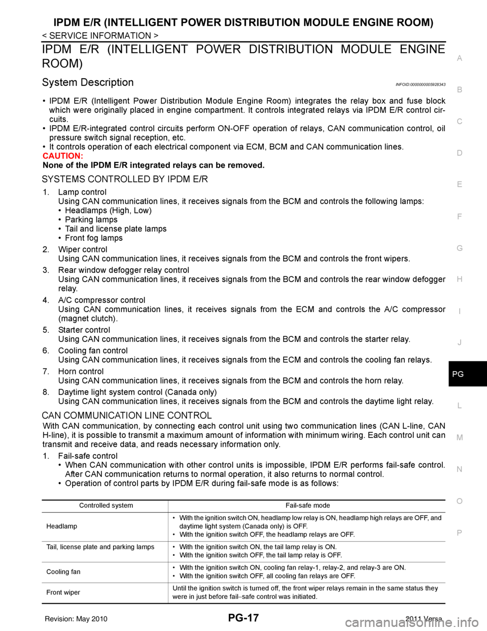
• IPDM E/R (Intelligent Power Distribution Module Engi ne Room) integrates the relay box and fuse block
which were originally placed in engine compartment. It controls integrated relays via IPDM E/R control cir-
cuits.
• IPDM E/R-integrated control circuits perform ON-OFF operation of relays, CAN communication control, oil pressure switch signal reception, etc.
• It controls operation of each electrical co mponent via ECM, BCM and CAN communication lines.
CAUTION:
None of the IPDM E/R integr ated relays can be removed.
SYSTEMS CONTROLLED BY IPDM E/R
1. Lamp control
Using CAN communication lines, it receives signals from the BCM and controls the following lamps:
• Headlamps (High, Low)
• Parking lamps
• Tail and license plate lamps
• Front fog lamps
2. Wiper control Using CAN communication lines, it receives signals from the BCM and controls the front wipers.
3. Rear window defogger relay control Using CAN communication lines, it receives signals from the BCM and controls the rear window defogger
relay.
4. A/C compressor control Using CAN communication lines, it receives signal s from the ECM and controls the A/C compressor
(magnet clutch).
5. Starter control Using CAN communication lines, it receives signals from the BCM and controls the starter relay.
6. Cooling fan control Using CAN communication lines, it receives signals from the ECM and controls the cooling fan relays.
7. Horn control Using CAN communication lines, it receives signals from the BCM and controls the horn relay.
8. Daytime light system control (Canada only) Using CAN communication lines, it receives signals from the BCM and controls the daytime light relay.
CAN COMMUNICATION LINE CONTROL
With CAN communication, by connecting each control unit using two communication lines (CAN L-line, CAN
H-line), it is possible to transmit a maximum amount of information with minimum wiring. Each control unit can
transmit and receive data, and reads necessary information only.
1. Fail-safe control • When CAN communication with other control units is impossible, IPDM E/R performs fail-safe control.
After CAN communication returns to normal operation, it also returns to normal control.
• Operation of control parts by IPDM E/ R during fail-safe mode is as follows:
Controlled system Fail-safe mode
Headlamp • With the ignition switch ON, headlamp low relay is ON, headlamp high relays are OFF, and
daytime light system (Canada only) is OFF.
• With the ignition switch OFF, the headlamp relays are OFF.
Tail, license plate and parking lamps • With the ignition switch ON, the tail lamp relay is ON. • With the ignition switch OFF, the tail lamp relay is OFF.
Cooling fan • With the ignition switch ON, cooling fan relay-1, relay-2, and relay-3 are ON.
• With the ignition switch OFF, all cooling fan relays are OFF.
Front wiper Until the ignition switch is turned off, the front wiper relays remain in the same status they
were in just before fail
−safe control was initiated.
Revision: May 2010 2011 Versa
Page 3446 of 3787

PG-26
< SERVICE INFORMATION >
IPDM E/R (INTELLIGENT POWER DISTRIBUTION MODULE ENGINE ROOM)
24 Y Cooling fan relay-3 Output — Conditions correct for cooling
fan high operation
Battery voltage
Conditions not correct for
cooling fan high operation 0V
26 O Tail lamp relay (park-
ing lamps) Output — Lighting switch in 2nd position Battery voltage
27 BR Tail lamp relay (park-
ing lamps)
Output — Lighting switch in 2nd position Battery voltage
28 GR Tail lamp relay (park-
ing lamps) Output — Lighting switch in 2nd position Battery voltage
29 P Tail lamp relay (park-
ing lamps) Output — Lighting switch in 2nd position Battery voltage
30
(A/T
only) R Fuse 54
Output —Ignition switch ON or START
Battery voltage
Ignition switch OFF or ACC 0V
31 O Fuse 55 Output —Ignition switch ON or START
Battery voltage
Ignition switch OFF or ACC 0V
32 L Wiper high speed sig-
nal
OutputON or
START Wiper switch OFF, LO, INT
0V
HI Battery voltage
33 Y Wiper low speed sig-
nal
OutputON or
START Wiper switch OFF
0V
LO or INT Battery voltage
35 BR Starter relay (inhibit
switch) InputON or
START Selector lever in "P" or "N"
(CVT or A/T) or clutch pedal
depressed (M/T)
Battery voltage
Selector lever any other posi-
tion (CVT or A/T) or clutch
pedal released (M/T) 0V
36 BR Fuel pump relay Output — Ignition switch ON or START
Battery voltage
Ignition switch OFF or ACC 0V
37 G Oil pressure switch Input ON or
START Engine running and oil pres-
sure within specification
Battery voltage
Engine not running or oil pres-
sure below specification 0V
38 R Wiper auto stop signal Input ON or
START Wipers not in park position
Battery voltage
Wipers in park position 0V
39 B Ground Input ——0V
40 P CAN-L — ON— —
41 L CAN-H — ON— —
45 R Horn relay control Input — Horn switch PUSHED, alarm
switch activated or door lock/
unlock is confirmed when op-
erating lock system via the
keyfob
0V
Horn switch released, alarm
not active, keyfob not active Battery voltage
46 Y Throttle control motor
relay control Input —Ignition switch ON or START
0V
Ignition switch OFF or ACC Battery voltage
47 GR Fuel pump relay con-
trol Input —Ignition switch ON or START
0V
Ig niti
on switch OFF or ACC Battery voltage
Te r m i n a l
Wire
color Signal name Signal
input/
output Measuring condition
Reference value
(Approx.)
Ignition
switch Operation or condition
Revision: May 2010
2011 Versa