Page 3464 of 3787
PG-44
< SERVICE INFORMATION >
HARNESS
Refer to "ENGINE ROOM HARNESS (LH VIEW)" for continuation of engine room harness.
G2 E1 GR/5 : Front wiper motor F2 E33 B/26 : ABS actuator and electric unit (control unit)
C3 E2 B/2 : Front and rear washer motor E2 E37 B/5 : Daytime light relay 1
F5 E4 Y/2 : Crash zone sensor D2 E38 L/5 : Daytime light relay 2
E4 E17 B/3 : Refrigerant pressure sensor E2 E41 — : Ground (ABS)
D2 E24 — : Engine ground C3 E50 W/2 : Washer fluid level switch
C3 E26 B/3 : Front combination lamp RH D1 E52 B/2 : Front wheel sensor RH
C4 E28 B/2 : Front fog lamp RH D2 E54 B/2 : Front combination lamp RH
D3 E30 B/2 : Front combination lamp RH
Revision: May 2010 2011 Versa
Page 3767 of 3787

FRONT WIPER AND WASHER SYSTEMWW-21
< SERVICE INFORMATION >
C
DE
F
G H
I
J
L
M A
B
WW
N
O P
INSTALLATION
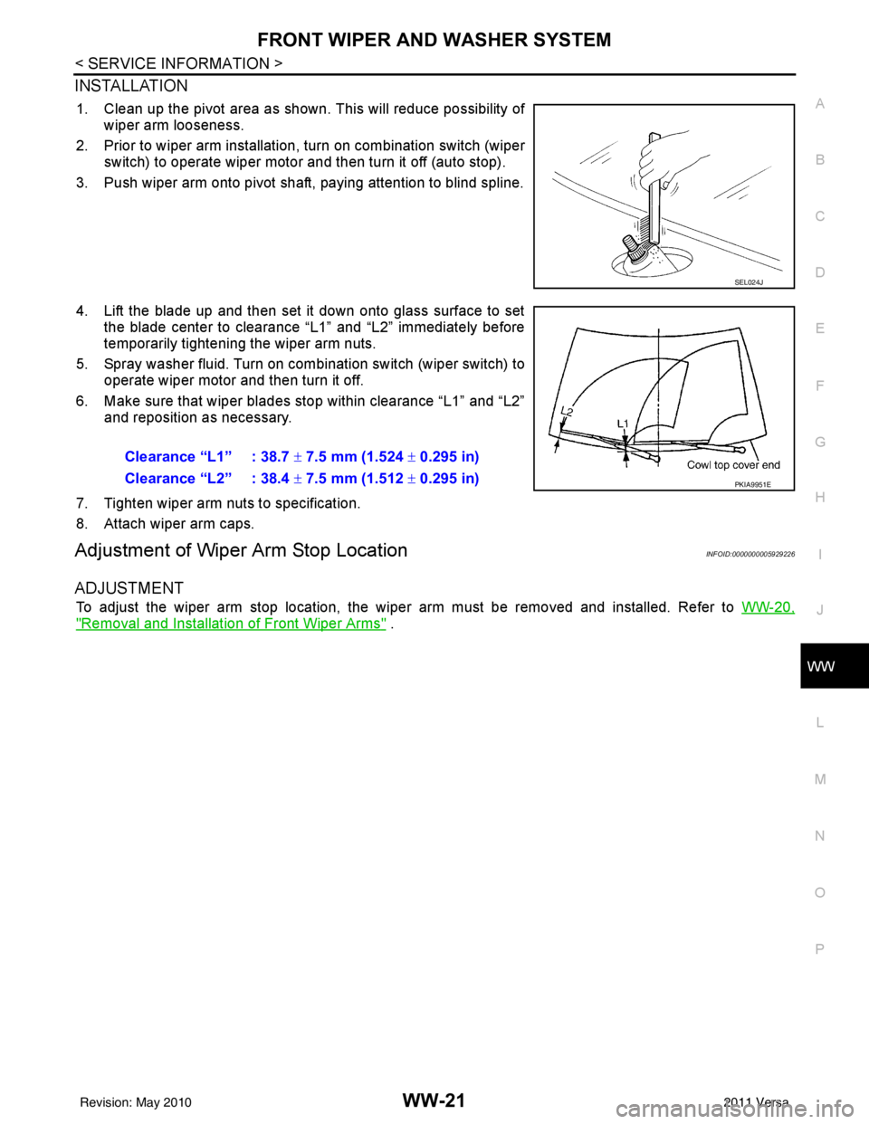
1. Clean up the pivot area as shown. This will reduce possibility of wiper arm looseness.
2. Prior to wiper arm installation, turn on combination switch (wiper switch) to operate wiper motor and then turn it off (auto stop).
3. Push wiper arm onto pivot shaft, paying attention to blind spline.
4. Lift the blade up and then set it down onto glass surface to set the blade center to clearance “L1” and “L2” immediately before
temporarily tightening the wiper arm nuts.
5. Spray washer fluid. Turn on combination switch (wiper switch) to operate wiper motor and then turn it off.
6. Make sure that wiper blades stop within clearance “L1” and “L2” and reposition as necessary.
7. Tighten wiper arm nuts to specification.
8. Attach wiper arm caps.
Adjustment of Wiper Arm Stop LocationINFOID:0000000005929226
ADJUSTMENT
To adjust the wiper arm stop location, the wiper arm must be removed and installed. Refer to WW-20,
"Removal and Installation of Front Wiper Arms" .
SEL024J
Clearance “L1” : 38.7 ± 7.5 mm (1.524 ± 0.295 in)
Clearance “L2” : 38.4 ± 7.5 mm (1.512 ± 0.295 in)
PKIA9951E
Revision: May 2010 2011 Versa
Page 3771 of 3787

FRONT WIPER AND WASHER SYSTEMWW-25
< SERVICE INFORMATION >
C
DE
F
G H
I
J
L
M A
B
WW
N
O P
Removal and Installation of Front Wiper and Washer SwitchINFOID:0000000005929232
REMOVAL
1. Remove the steering column cover. Refer to IP-11 .
2. Disconnect the wiper and washer switch connector.
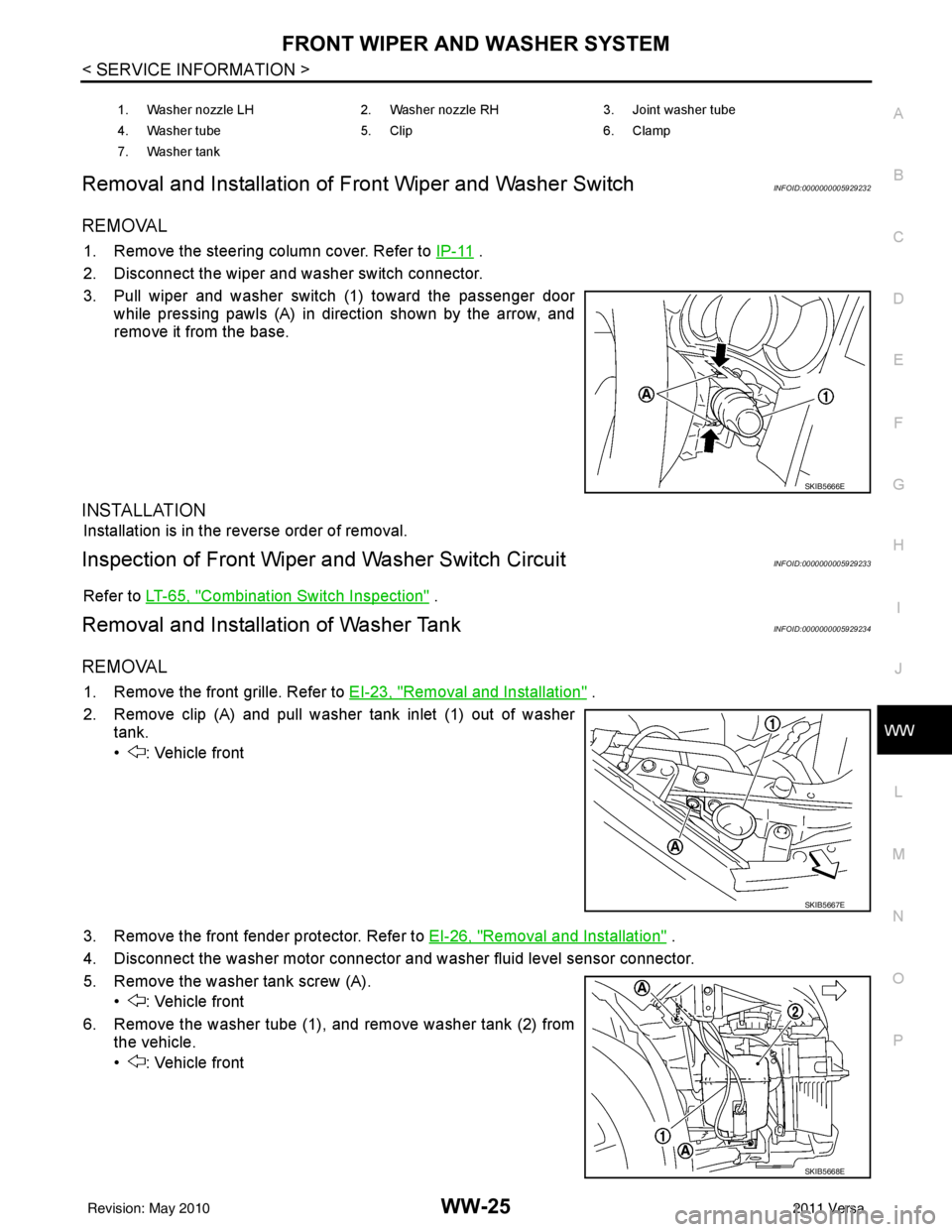
3. Pull wiper and washer switch (1) toward the passenger door while pressing pawls (A) in direction shown by the arrow, and
remove it from the base.
INSTALLATION
Installation is in the reverse order of removal.
Inspection of Front Wiper and Washer Switch CircuitINFOID:0000000005929233
Refer to LT-65, "Combination Switch Inspection" .
Removal and Installation of Washer TankINFOID:0000000005929234
REMOVAL
1. Remove the front grille. Refer to EI-23, "Removal and Installation" .
2. Remove clip (A) and pull washer tank inlet (1) out of washer tank.
• : Vehicle front
3. Remove the front fender protector. Refer to EI-26, "
Removal and Installation" .
4. Disconnect the washer motor connector and washer fluid level sensor connector.
5. Remove the washer tank screw (A). • : Vehicle front
6. Remove the washer tube (1), and remove washer tank (2) from the vehicle.
• : Vehicle front
1. Washer nozzle LH 2. Washer nozzle RH 3. Joint washer tube
4. Washer tube 5. Clip 6. Clamp
7. Washer tank
SKIB5666E
SKIB5667E
SKIB5668E
Revision: May 2010 2011 Versa
Page 3782 of 3787
WW-36
< SERVICE INFORMATION >
REAR WIPER AND WASHER SYSTEM
Removal
1. Remove wiper arm. Refer to "REAR WIPER ARM" .
2. Raise arm cap.
3. Remove the rear wiper motor nut, remove the rear wiper arm and blade.
4. Remove the back door lower finisher. Refer to EI-40, "
Removal and Installation" .
5. Disconnect the rear wiper motor connector (B).
6. Remove the bolts (A) and remove the rear wiper motor (1).
Installation
Installation is in the reverse order of removal.
CAUTION:
Do not drop the wiper motor or cause it to contact other parts.
REAR WASHER TUBE LAYOUT
NOTE:
Connect the check valve (2) to the washer fluid tube (1) so that the
directional arrow on the check valve (2) points towards the washer
nozzle tube (3).
REAR WASHER NOZZLE
LKIA0789E
1 Washer fluid reservoir 2 Washer fluid tube to rear door 3 Check valve
4 Rear washer nozzle
LKIA0790E
WKIA4242E
Revision: May 2010 2011 Versa
Page 3783 of 3787

REAR WIPER AND WASHER SYSTEMWW-37
< SERVICE INFORMATION >
C
DE
F
G H
I
J
L
M A
B
WW
N
O P
Removal
1. Remove the back door side garnish. Refer to
EI-40, "Removal and Installation" .
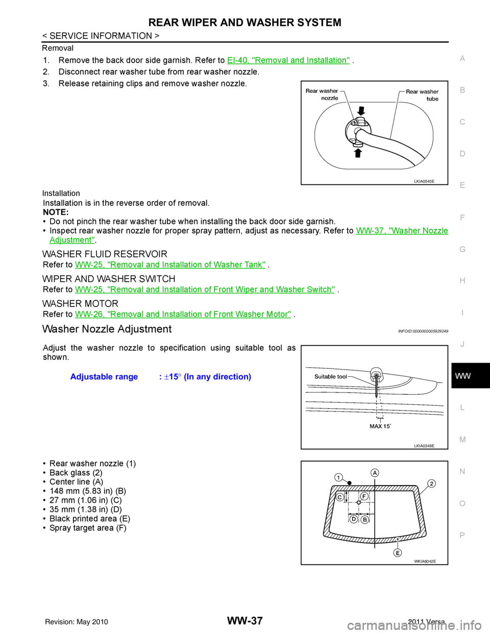
2. Disconnect rear washer tube from rear washer nozzle.
3. Release retaining clips and remove washer nozzle.
Installation
Installation is in the reverse order of removal.
NOTE:
• Do not pinch the rear washer tube when installing the back door side garnish.
• Inspect rear washer nozzle for proper spray pattern, adjust as necessary. Refer to WW-37, "
Washer Nozzle
Adjustment".
WASHER FLUID RESERVOIR
Refer to WW-25, "Removal and Installation of Washer Tank" .
WIPER AND WASHER SWITCH
Refer to WW-25, "Removal and Installation of Front Wiper and Washer Switch" .
WASHER MOTOR
Refer to WW-26, "Removal and Installation of Front Washer Motor" .
Washer Nozzle AdjustmentINFOID:0000000005929249
Adjust the washer nozzle to specification using suitable tool as
shown.
• Rear washer nozzle (1)
• Back glass (2)
• Center line (A)
• 148 mm (5.83 in) (B)
• 27 mm (1.06 in) (C)
• 35 mm (1.38 in) (D)
• Black printed area (E)
• Spray target area (F)
LKIA0545E
Adjustable range : ±15° (In any direction)
LKIA0349E
WKIA6042E
Revision: May 2010 2011 Versa