2011 NISSAN TIIDA body control
[x] Cancel search: body controlPage 1 of 3787

-1
QUICK REFERENCE INDEX
AGENERAL INFORMATIONGIGeneral Information
BENGINEEMEngine Mechanical
LUEngine Lubrication System
COEngine Cooling System
ECEngine Control System
FLFuel System
EXExhaust System
ACCAccelerator Control System
CTRANSMISSION/
TRANSAXLECLClutch System
MTManual Transaxle
ATAutomatic Transaxle
CVTCVT
DDRIVELINE/AXLEFAXFront Axle
RAXRear Axle
ESUSPENSIONFSUFront Suspension
RSURear Suspension
WTRoad Wheels & Tires
FBRAKESBRBrake System
PBParking Brake System
BRCBrake Control System
GSTEERINGPSPower Steering System
STCSteering Control System
HRESTRAINTSSBSeat Belts
SRSSupplemental Restraint System (SRS)
IBODYBLBody, Lock & Security System
GWGlasses, Window System & Mirrors
RFRoof
EIExterior & Interior
IPInstrument Panel
SESeat
JAIR CONDITIONERMTCManual Air Conditioner
KELECTRICALSCStarting & Charging System
LTLighting System
DIDriver Information System
WWWiper, Washer & Horn
BCSBody Control System
LANLAN System
AVAudio Visual, Navigation & Telephone System
ACSAuto Cruise Control System
PGPower Supply, Ground & Circuit Elements
LMAINTENANCEMAMaintenance
Edition: May 2010
Revision: May 2010
Publication No. SM1E-1C11U0
B
D
© 2010 NISSAN NORTH AMERICA, INC.
All rights reserved. No part of this Service Manual may be reproduced or stored in a retrieval system, or transmitted in any
form, or by any means, electronic, mechanical, photo-copying, recording or otherwise, without the prior written permission
of Nissan North America Inc.
A
C
E
F
G
H
I
J
K
L
M
Page 21 of 3787

AT-4
Transmission Range Switch ..................................225
Output Speed Sensor ............................................227
Input Speed Sensor ...............................................228
Differential Side Oil Seal ........................................229
AIR BREATHER HOSE ...................................232
Removal and Installation ..................................... ..232
TRANSAXLE ASSEMBLY ..............................233
Removal and Installation ..................................... ..233
OVERHAUL .................................................... .237
Component .......................................................... ..237
Oil Channel ............................................................250
Location of Adjusting Shims, Needle Bearings and
Thrust Washers .....................................................
253
Location of Snap Rings .........................................255
DISASSEMBLY .............................................. .257
Disassembly ........................................................ ..257
REPAIR FOR COMPONENT PARTS ..............275
Manual Shaft ....................................................... ..275
Oil Pump ................................................................278
Control Valve Assembly ........................................281
Control Valve Upper Body .....................................290
Control Valve Lower Body ................................... ..294
Reverse Clutch ......................................................297
High Clutch ............................................................302
Forward and Overrun Clutches .............................307
Low & Reverse Brake ............................................314
Rear Internal Gear and Forward Clutch Hub .........318
Output Shaft, Output Gear, Idler Gear, Reduction
Pinion Gear and Bearing Retainer .........................
322
Band Servo Piston Assembly ................................331
Final Drive .............................................................337
ASSEMBLY .....................................................344
Assembly (1) ........................................................ ..344
Adjustment (1) (For HR16DE Engine Models) ..... .345
Adjustment (1) (For MR18DE Engine Models) .....349
Assembly (2) .........................................................355
Adjustment (2) .......................................................360
Assembly (3) .........................................................363
SERVICE DATA AND SPECIFICATIONS
(SDS) ................................................................
373
General Specification ........................................... .373
Vehicle Speed at Which Gear Shifting Occurs .....373
Vehicle Speed at When Lock-up Occurs/Releases
.
373
Stall Speed ............................................................374
Line Pressure ........................................................374
Adjusting shims, Needle Bearings, Thrust Wash-
ers and Snap Rings ..............................................
374
Control Valves .......................................................375
Accumulator ..........................................................376
Clutches and Brakes .............................................376
Final Drive .............................................................378
Planetary Carrier ...................................................378
Oil Pump ...............................................................378
Input Shaft .............................................................378
Reduction Pinion Gear ..........................................378
Band Servo ...........................................................378
Output Shaft ..........................................................379
Bearing Retainer ...................................................379
Total End Play ...................................................... .379
Reverse Clutch End Play ......................................379
Removal and Installation .......................................379
Shift Solenoid Valves ........................................... .379
Solenoid Valves ....................................................380
A/T Fluid Temperature Sensor ..............................380
Output Speed Sensor ...........................................380
Dropping Resistor .................................................380
Input Speed Sensor ..............................................380
Revision: May 2010 2011 Versa
Page 124 of 3787
P0725 ENGINE SPEEDAT-107
< SERVICE INFORMATION >
DE
F
G H
I
J
K L
M A
B
AT
N
O P
Diagnosis ProcedureINFOID:0000000005928142
1.CHECK DTC WITH ECM
Check DTC with CONSULT-III “ENGINE”.
Turn ignition switch ON and select “SELF-DIAGNOST IC RESULTS” mode for “ENGINE” with CONSULT-III.
Refer to EC-106, "
CONSULT-III Function" (HR16DE), EC-612, "CONSULT-III Function (ENGINE)" (MR18DE).
OK or NG
OK >> GO TO 2.
NG >> Check ignition signal circuit for engine control. Refer to EC-442, "
Description" (HR16DE), EC-
1019, "Component Description" (MR18DE).
2.CHECK INPUT SIGNAL
With CONSULT-III
1. Start engine.
2. Select “TCM INPUT SIGNALS” in “DATA MONI TOR” mode for “TRANSMISSION” with CONSULT-III.
3. Read out the value of “ENGINE SPEED”. Check engine speed changes according to throttle position.
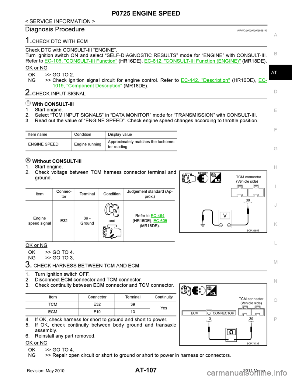
Without CONSULT-III
1. Start engine.
2. Check voltage between TCM harness connector terminal and ground.
OK or NG
OK >> GO TO 4.
NG >> GO TO 3.
3. CHECK HARNESS BETWEEN TCM AND ECM
1. Turn ignition switch OFF.
2. Disconnect ECM connector and TCM connector.
3. Check continuity between ECM connector and TCM connector.
4. If OK, check harness for short to ground and short to power.
5. If OK, check continuity between body ground and transaxle
assembly.
6. Reinstall any part removed.
OK or NG
OK >> GO TO 4.
NG >> Repair open circuit or short to ground or short to power in harness or connectors.
Item name Condition Display value
ENGINE SPEED Engine running Approximately matches the tachome-
ter reading.
itemConnec-
tor Terminal Condition Judgement standard (Ap-
prox.)
Engine
speed signal E3239 -
Ground
and Refer to EC-464
(HR16DE), EC-605
(MR18DE).
SCIA3265E
Item Connector Terminal Continuity
TCM E3239
Ye s
ECM F1013
SCIA7173E
Revision: May 2010 2011 Versa
Page 240 of 3787
ON-VEHICLE SERVICEAT-223
< SERVICE INFORMATION >
DE
F
G H
I
J
K L
M A
B
AT
N
O P
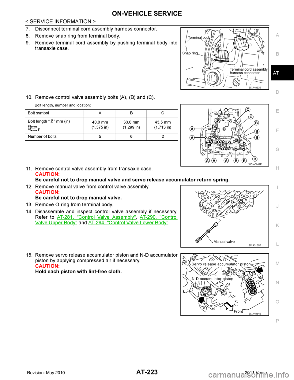
7. Disconnect terminal cord assembly harness connector.
8. Remove snap ring from terminal body.
9. Remove terminal cord assembly by pushing terminal body into transaxle case.
10. Remove control valve assembly bolts (A), (B) and (C).
Bolt length, number and location:
11. Remove control valve assembly from transaxle case. CAUTION:
Be careful not to drop manual valve and servo release accumulato r return spring.
12. Remove manual valve from control valve assembly. CAUTION:
Be careful not to drop manual valve.
13. Remove O-ring from terminal body.
14. Disassemble and inspect control valve assembly if necessary. Refer to AT-281, "
Control Valve Assembly", AT-290, "Control
Valve Upper Body" and AT-294, "Control Valve Lower Body".
15. Remove servo release accumulator piston and N-D accumulator piston by applying compressed air if necessary.
CAUTION:
Hold each piston with lint-free cloth.
SCIA4853E
Bolt symbol ABC
Bolt length “ ” mm (in) 40.0 mm
(1.575 in) 33.0 mm
(1.299 in) 43.5 mm
(1.713 in)
Number of bolts 562
WCIA0649E
SCIA3150E
SCIA4854E
Revision: May 2010 2011 Versa
Page 276 of 3787
DISASSEMBLYAT-259
< SERVICE INFORMATION >
DE
F
G H
I
J
K L
M A
B
AT
N
O P
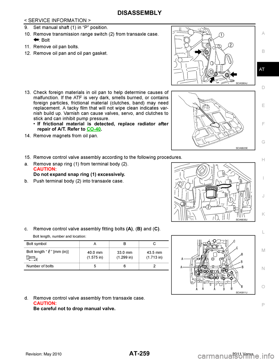
9. Set manual shaft (1) in “P” position.
10. Remove transmission range switch (2) from transaxle case. : Bolt
11. Remove oil pan bolts.
12. Remove oil pan and oil pan gasket.
13. Check foreign materials in oil pan to help determine causes of malfunction. If the ATF is very dark, smells burned, or contains
foreign particles, frictional material (clutches, band) may need
replacement. A tacky film that will not wipe clean indicates var-
nish build up. Varnish can cause valves, servo, and clutches to
stick and can inhibit pump pressure.
•If frictional material is detected, replace radiator after
repair of A/T. Refer to CO-40
.
14. Remove magnets from oil pan.
15. Remove control valve assembly according to the following procedures.
a. Remove snap ring (1) from terminal body (2). CAUTION:
Do not expand snap ring (1) excessively.
b. Push terminal body (2) into transaxle case.
c. Remove control valve assembly fitting bolts (A), (B) and ( C).
Bolt length, number and location:
d. Remove control valve assembly from transaxle case.
CAUTION:
Be careful not to drop manual valve.
SCIA5904J
SCIA8025E
SCIA6030J
Bolt symbol ABC
Bolt length “ ” [mm (in)] 40.0 mm
(1.575 in) 33.0 mm
(1.299 in) 43.5 mm
(1.713 in)
Number of bolts 562
SCIA5911J
Revision: May 2010 2011 Versa
Page 277 of 3787
AT-260
< SERVICE INFORMATION >
DISASSEMBLY
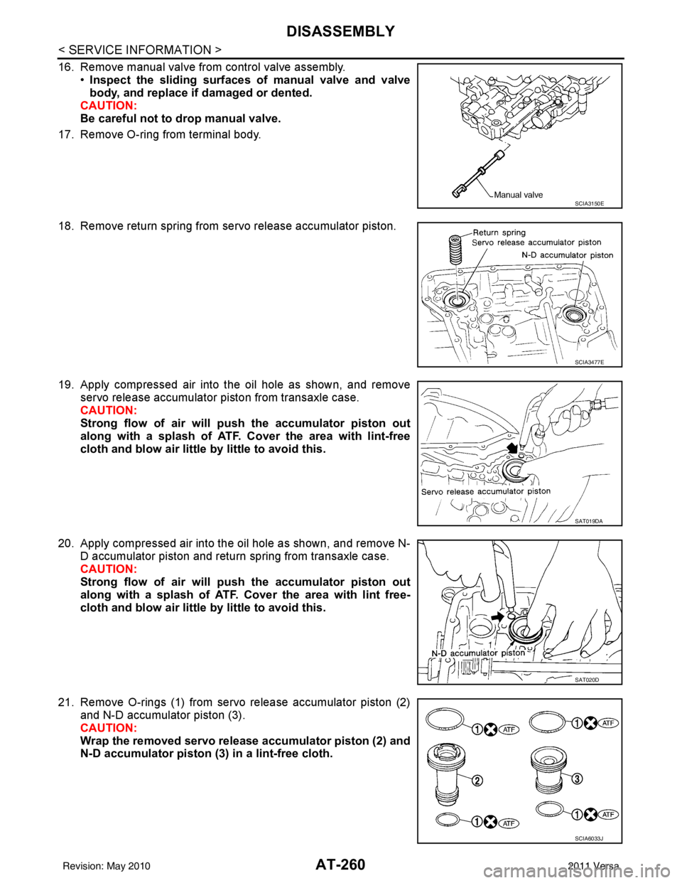
16. Remove manual valve from control valve assembly.•Inspect the sliding surfaces of manual valve and valve
body, and replace if damaged or dented.
CAUTION:
Be careful not to drop manual valve.
17. Remove O-ring from terminal body.
18. Remove return spring from servo release accumulator piston.
19. Apply compressed air into the oil hole as shown, and remove servo release accumulator piston from transaxle case.
CAUTION:
Strong flow of air will push the accumulator piston out
along with a splash of ATF. Cover the area with lint-free
cloth and blow air little by little to avoid this.
20. Apply compressed air into the oil hole as shown, and remove N- D accumulator piston and return spring from transaxle case.
CAUTION:
Strong flow of air will push the accumulator piston out
along with a splash of ATF. Cover the area with lint free-
cloth and blow air little by little to avoid this.
21. Remove O-rings (1) from servo release accumulator piston (2) and N-D accumulator piston (3).
CAUTION:
Wrap the removed servo release accumulator piston (2) and
N-D accumulator piston (3) in a lint-free cloth.
SCIA3150E
SCIA3477E
SAT019DA
SAT020D
SCIA6033J
Revision: May 2010 2011 Versa
Page 299 of 3787
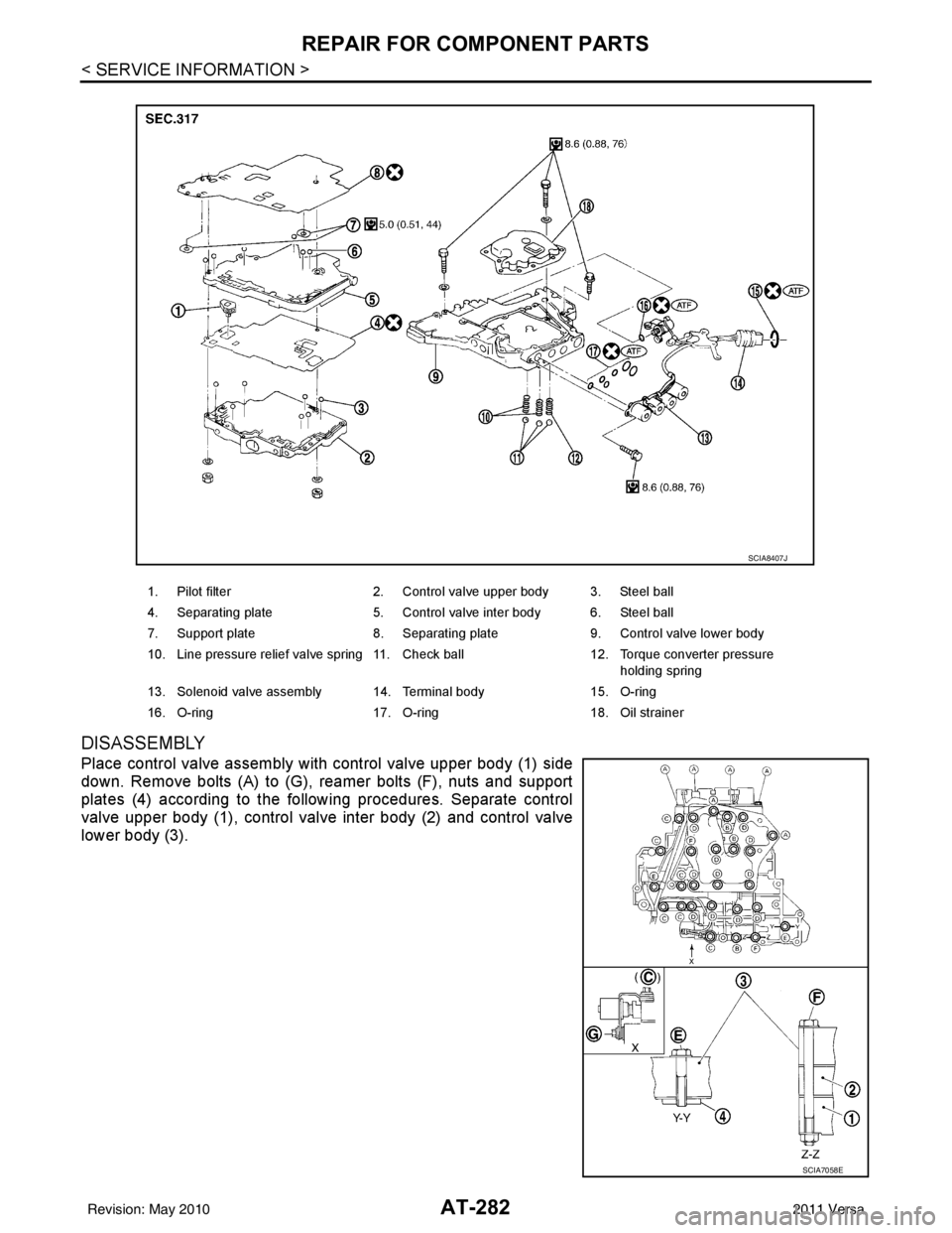
AT-282
< SERVICE INFORMATION >
REPAIR FOR COMPONENT PARTS
DISASSEMBLY
Place control valve assembly with control valve upper body (1) side
down. Remove bolts (A) to (G), reamer bolts (F), nuts and support
plates (4) according to the following procedures. Separate control
valve upper body (1), control valve inter body (2) and control valve
lower body (3).
1. Pilot filter2. Control valve upper body 3. Steel ball
4. Separating plate 5. Control valve inter body 6. Steel ball
7. Support plate 8. Separating plate9. Control valve lower body
10. Line pressure relief valve spring 11. Check ball 12. Torque converter pressure
holding spring
13. Solenoid valve assembly 14. Terminal body 15. O-ring
16. O-ring 17. O-ring18. Oil strainer
SCIA8407J
SCIA7058E
Revision: May 2010 2011 Versa
Page 300 of 3787
REPAIR FOR COMPONENT PARTSAT-283
< SERVICE INFORMATION >
DE
F
G H
I
J
K L
M A
B
AT
N
O P
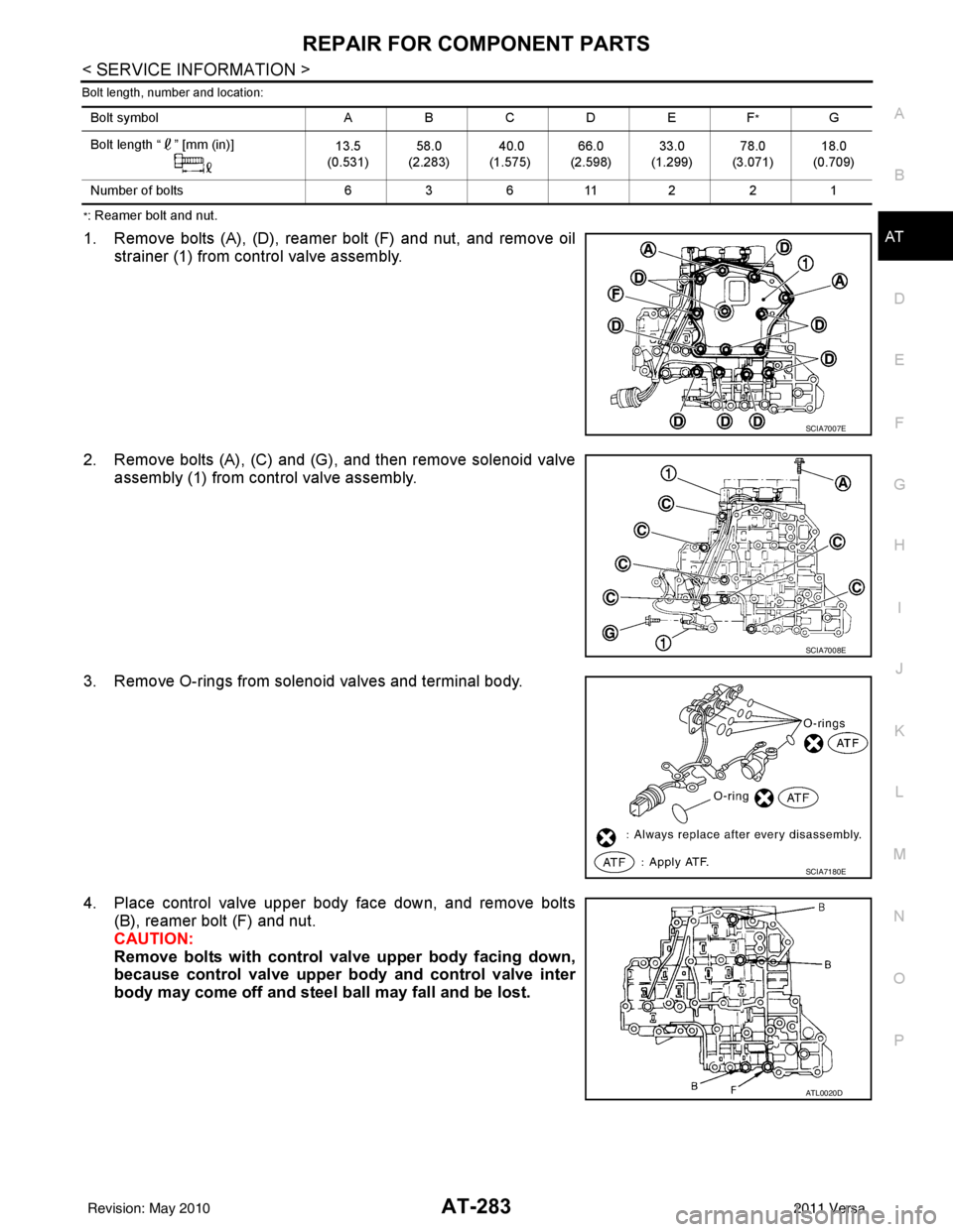
Bolt length, number and location:
*: Reamer bolt and nut.
1. Remove bolts (A), (D), reamer bolt (F) and nut, and remove oil strainer (1) from control valve assembly.
2. Remove bolts (A), (C) and (G), and then remove solenoid valve assembly (1) from control valve assembly.
3. Remove O-rings from solenoid valves and terminal body.
4. Place control valve upper body face down, and remove bolts (B), reamer bolt (F) and nut.
CAUTION:
Remove bolts with control val ve upper body facing down,
because control valve upper body and control valve inter
body may come off and steel ball may fall and be lost.
Bolt symbol ABC D EF*G
Bolt length “ ” [mm (in)] 13.5
(0.531) 58.0
(2.283) 40.0
(1.575) 66.0
(2.598) 33.0
(1.299) 78.0
(3.071) 18.0
(0.709)
Number of bolts 63 611 221
SCIA7007E
SCIA7008E
SCIA7180E
ATL0020D
Revision: May 2010 2011 Versa