Page 311 of 3787

AT-294
< SERVICE INFORMATION >
REPAIR FOR COMPONENT PARTS
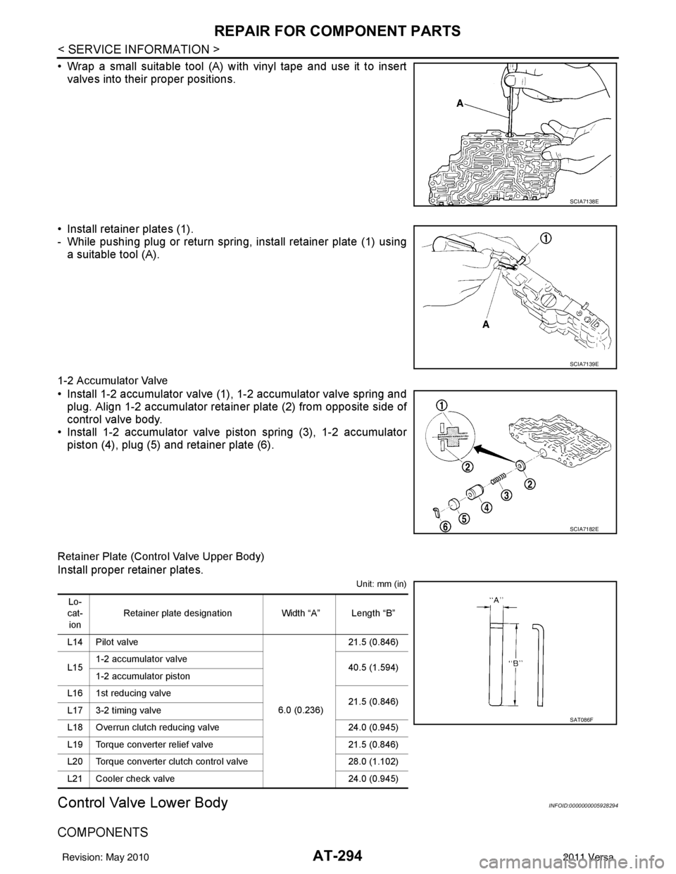
• Wrap a small suitable tool (A) with vinyl tape and use it to insertvalves into their proper positions.
• Install retainer plates (1).
- While pushing plug or return spring, install retainer plate (1) using a suitable tool (A).
1-2 Accumulator Valve
• Install 1-2 accumulator valve (1), 1-2 accumulator valve spring and
plug. Align 1-2 accumulator retainer plate (2) from opposite side of
control valve body.
• Install 1-2 accumulator valve piston spring (3), 1-2 accumulator
piston (4), plug (5) and retainer plate (6).
Retainer Plate (Control Valve Upper Body)
Install proper retainer plates.
Unit: mm (in)
Control Valve Lower BodyINFOID:0000000005928294
COMPONENTS
SCIA7138E
SCIA7139E
SCIA7182E
Lo-
cat-
ion Retainer plate designation
Width “A” Length “B”
L14 Pilot valve
6.0 (0.236)21.5 (0.846)
L15 1-2 accumulator valve
40.5 (1.594)
1-2 accumulator piston
L16 1st reducing valve 21.5 (0.846)
L17 3-2 timing valve
L18 Overrun clutch reducing valve 24.0 (0.945)
L19 Torque converter relief valve 21.5 (0.846)
L20 Torque converter clutch control valve 28.0 (1.102)
L21 Cooler check valve 24.0 (0.945)
SAT086F
Revision: May 2010 2011 Versa
Page 312 of 3787
REPAIR FOR COMPONENT PARTSAT-295
< SERVICE INFORMATION >
DE
F
G H
I
J
K L
M A
B
AT
N
O P
1. Retainer plate 2. Pressure modifier piston spring 3. Pressure modifier piston
4. Parallel pin 5. Sleeve6. Pressure modifier valve spring
7. Pressure modifier valve 8. Control valve lower body9. Manual valve
10. Pressure regulator valve 11. Pressure regulator valve spring 12. Spring seat
13. Plug 14. Retainer plate15. Sleeve
16. Overrun clutch control valve spring 17. Overrun clutch control valve 18. Plug
SCIA2959J
Revision: May 2010 2011 Versa
Page 313 of 3787

AT-296
< SERVICE INFORMATION >
REPAIR FOR COMPONENT PARTS
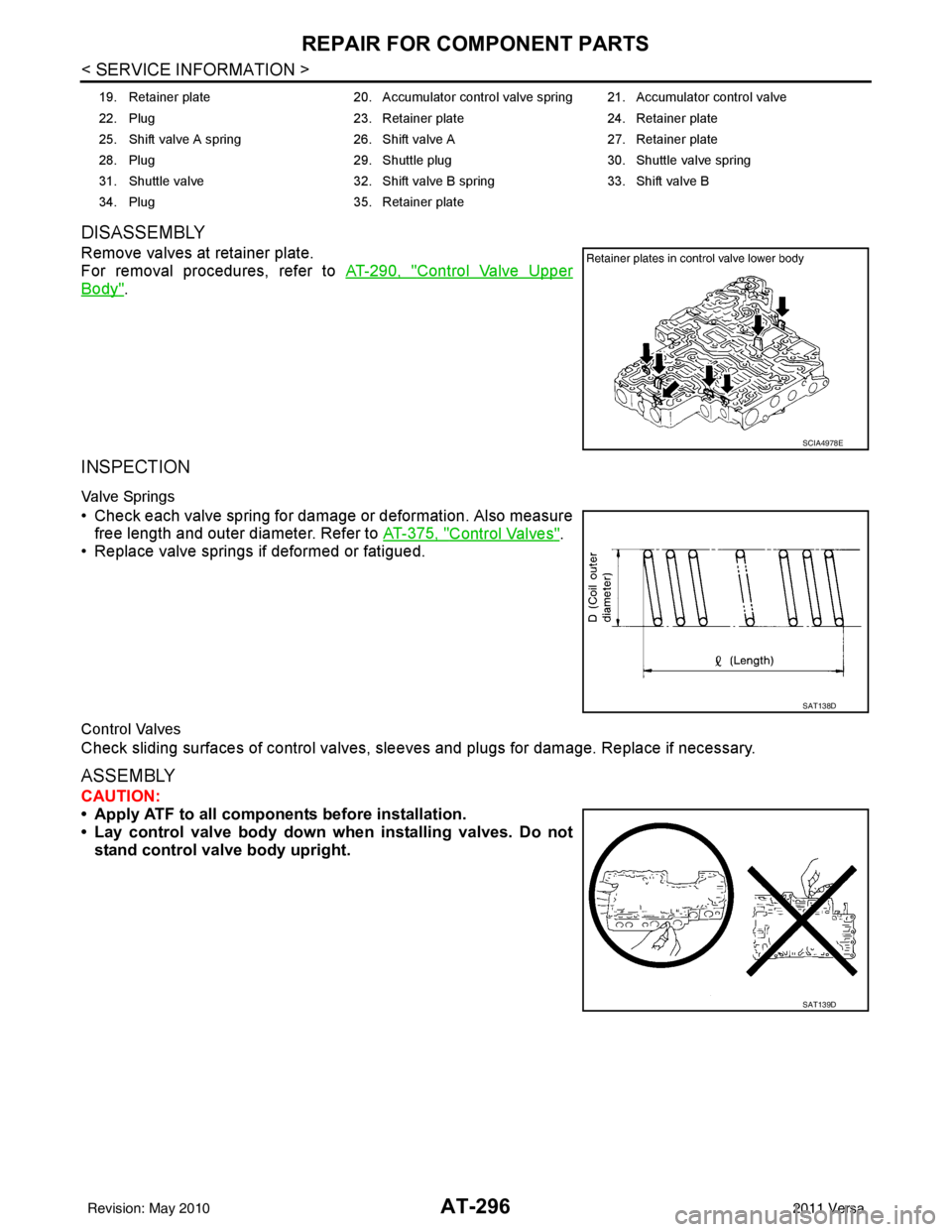
DISASSEMBLY
Remove valves at retainer plate.
For removal procedures, refer to AT-290, "
Control Valve Upper
Body".
INSPECTION
Valve Springs
• Check each valve spring for damage or deformation. Also measure
free length and outer diameter. Refer to AT-375, "
Control Valves".
• Replace valve springs if deformed or fatigued.
Control Valves
Check sliding surfaces of control valves, sl eeves and plugs for damage. Replace if necessary.
ASSEMBLY
CAUTION:
• Apply ATF to all components before installation.
• Lay control valve body down wh en installing valves. Do not
stand control valve body upright.
19. Retainer plate 20. Accumulator control valve spring 21. Accumulator control valve
22. Plug 23. Retainer plate24. Retainer plate
25. Shift valve A spring 26. Shift valve A27. Retainer plate
28. Plug 29. Shuttle plug 30. Shuttle valve spring
31. Shuttle valve 32. Shift valve B spring33. Shift valve B
34. Plug 35. Retainer plate
SCIA4978E
SAT138D
SAT139D
Revision: May 2010 2011 Versa
Page 314 of 3787
REPAIR FOR COMPONENT PARTSAT-297
< SERVICE INFORMATION >
DE
F
G H
I
J
K L
M A
B
AT
N
O P
Install control valves.
For installation procedures, refer to AT-290, "
Control Valve Upper
Body".
Retainer Plate (Control Valve Lower Body)
Install proper retainer plates.
Unit: mm (in)
Reverse ClutchINFOID:0000000005928295
COMPONENTS
DISASSEMBLY
SCIA4978E
Lo-
cat- ion Retainer plate designation Width “A” Length “B” Type
L3 Pressure regulator valve 6.0
(0.236) 28.0
(1.102) I
L4 Overrun clutch control valve
L5 Accumulator control valve
L6 Shift valve A
L7 Shuttle valve
L12 Shift valve B 17.0
(0.669) 24.0
(0.945) II
L13 Pressure modifier valve 6.0
(0.236) 28.0
(1.102) I
SAT089F
1. Reverse clutch drum
2. D-ring 3. Seal lip
4. Reverse clutch piston 5. Spring retainer assembly 6. Snap ring
7. Dish plate 8. Driven plate 9. Retaining plate
10. Snap ring 11. Drive plate
SCIA6939J
Revision: May 2010 2011 Versa
Page 386 of 3787
ASSEMBLYAT-369
< SERVICE INFORMATION >
DE
F
G H
I
J
K L
M A
B
AT
N
O P
28. Install lip seals (1) for band servo oil holes on transaxle case.
29. Install control valve assembly on transaxle case.
a. Install O-ring on terminal body. CAUTION:
• Do not reuse O-ring.
• Apply ATF to O-ring.
b. Insert manual valve into control valve assembly. CAUTION:
Be careful not to drop manual valve.
c. Set manual shaft in “N” position.
d. Install control valve assembly on transaxle case while aligning manual valve (2) with manual plate (1).
e. Install terminal body (2) into transaxle case by pushing it.
f. Install snap ring (1) to terminal body (2).
g. Tighten bolts (A), (B) and (C) to the specified torque. Refer to AT-237, "
Component".
SCIA5895J
SCIA3999E
SCIA7090E
SCIA6030J
Revision: May 2010 2011 Versa
Page 393 of 3787

AT-376
< SERVICE INFORMATION >
SERVICE DATA AND SPECIFICATIONS (SDS)
Unit: mm (in)
AccumulatorINFOID:0000000005928316
RETURN SPRINGS
Unit: mm (in)
Unit: mm (in)
O-RINGS
Unit: mm (in)
Clutches and BrakesINFOID:0000000005928317
REVERSE CLUTCH
Locationspring designation Free length (l) Outer diameter (D)
Upper body L14 Pilot valve spring
38.98 (1.5346)8.9 (0.350)
L15 1–2 accumulator valve spring
20.5 (0.807)6.95 (0.2736)
1–2 accumulator piston spring 55.66 (2.1913)19.5 (0.768)
L16 1st reducing valve spring 27.0 (1.063)7.0 (0.276)
L17 3–2 timing valve spring 23.0 (0.906)6.65 (0.2618)
L18 Overrun clutch reducing valve spring37.5 (1.476)7.0 (0.276)
L19 Torque converter relief valve spring 33.3 (1.311)9.0 (0.354)
L20 Torque converter clutch control valve spring 53.01 (2.0870)6.5 (0.256)
L21 Cooler check valve spring 28.04 (1.1039)7.15 (0.2815)
Lower body L3 Pressure regulator valve spring
45.0 (1.772)15.0 (0.591)
L4 Overrun clutch control valve spring 21.7 (0.854)7.0 (0.276)
L5 Accumulator control valve spring 22.0 (0.866)6.5 (0.256)
L6 Shift valve A spring 21.7 (0.854)7.0 (0.276)
L7 Shuttle valve spring 51.0 (2.008)5.65 (0.2224)
L12 Shift valve B spring 21.7 (0.854)7.0 (0.276)
L13 Pressure modifier valve spring
32.0 (1.260)6.9 (0.272)
Pressure modifier piston spring 30.5 (1.201)9.8 (0.386)
— Line pressure relief valve spring 17.02 (0.6701)8.0 (0.315)
— Torque converter pressure holding spring 9.0 (0.354)7.3 (0.287)
Location Free length (L1)
Servo release accumulator 62.8 (2.472)
LocationLength (L2)
N-D accumulator 46.5 (1.831)
LocationInner diameter (Small) Inner diameter (Large)
Servo release accumulator 26.9 (1.059)44.2 (1.740)
N-D accumulator 34.6 (1.362)39.4 (1.551)
Number of drive plates 2
Number of driven plates 2
Drive plate thickness [mm (in)] Standard
2.0 (0.079)
Allowable limit 1.8 (0.071)
Driven plate thickness [mm (in)] Standard 2.0 (0.079)
Clearance [mm (in)] Standard
0.5 - 0.8 (0.020 - 0.031)
Allowable limit 1.2 (0.047)
Revision: May 2010 2011 Versa
Page 404 of 3787
![NISSAN TIIDA 2011 Service Repair Manual AUDIOAV-7
< SERVICE INFORMATION > [AUDIO WITHOUT NAVIGATION]
C
D
E
F
G H
I
J
L
M A
B
AV
N
O P
• to audio unit terminal 19.
With the ignition switch in the ACC or ON position, power is supplied
• t NISSAN TIIDA 2011 Service Repair Manual AUDIOAV-7
< SERVICE INFORMATION > [AUDIO WITHOUT NAVIGATION]
C
D
E
F
G H
I
J
L
M A
B
AV
N
O P
• to audio unit terminal 19.
With the ignition switch in the ACC or ON position, power is supplied
• t](/manual-img/5/57396/w960_57396-403.png)
AUDIOAV-7
< SERVICE INFORMATION > [AUDIO WITHOUT NAVIGATION]
C
D
E
F
G H
I
J
L
M A
B
AV
N
O P
• to audio unit terminal 19.
With the ignition switch in the ACC or ON position, power is supplied
• through 10A fuse (No. 20, located in the fuse and fusible link box)
• to audio unit terminal 7.
Ground is supplied through the case of the audio unit.
Then audio signals are supplied
• through audio unit terminals 2, 3, 4, 5, 11, 12, 13 and 14
• to terminals + and - of front door speaker LH and RH and
• to terminals + and - of rear door speaker LH and RH.
PREMIUM SYSTEM
Refer to Owner's Manual for audio system operating instructions.
Power is supplied at all times
• through 20A fuse (No. 27, located in the fuse and fusible link box)
• to audio unit terminal 19.
With the ignition switch in the ACC or ON position, power is supplied
• through 10A fuse (No. 20, located in the fuse and fusible link box)
• to audio unit terminal 7.
Ground is supplied
• to audio unit terminals 20 and 61
• through body grounds M57 and M61.
Then audio signals are supplied
• through audio unit terminals 2, 3, 4, 5, 11, 12, 13, and 14
• to terminals + and - of front door speaker LH and RH and
• to terminals + and - of front tweeter LH and RH and
• to terminals + and - of rear door speaker LH and RH.
Steering Wheel Audio Contro l Switches (with Bluetooth)
When one of steering wheel audio control switches is pus hed, the resistance in steering switch circuit changes
depending on which button is pushed.
SPEED SENSITIVE VOLUME SYSTEM (PREMIUM SYSTEM)
Volume level of this system goes up and down automatica lly in proportion to the vehicle speed. The control
level can be selected by the customer. Refer to Owner's Manual for operating instructions.
Revision: May 2010 2011 Versa
Page 463 of 3787
![NISSAN TIIDA 2011 Service Repair Manual AV-66
< SERVICE INFORMATION >[AUDIO WITH NAVIGATION]
AUDIO
END ON-BOARD DIAGNOSIS
Turn OFF ignition switch.
Noise InspectionINFOID:0000000005931317
The vehicle itself can be a source of noise if noise NISSAN TIIDA 2011 Service Repair Manual AV-66
< SERVICE INFORMATION >[AUDIO WITH NAVIGATION]
AUDIO
END ON-BOARD DIAGNOSIS
Turn OFF ignition switch.
Noise InspectionINFOID:0000000005931317
The vehicle itself can be a source of noise if noise](/manual-img/5/57396/w960_57396-462.png)
AV-66
< SERVICE INFORMATION >[AUDIO WITH NAVIGATION]
AUDIO
END ON-BOARD DIAGNOSIS
Turn OFF ignition switch.
Noise InspectionINFOID:0000000005931317
The vehicle itself can be a source of noise if noise
prevention parts or electrical equipment is malfunctioning.
Check if noise is caused and/or changed by engine speed, ignition switch turned to each position, and opera-
tion of each piece of electrical equipment, and determine the cause.
NOTE:
The source of the noise can be found easily by listening to the noise while removing the fuses of electrical
components, one by one.
TYPE OF NOISE AND POSSIBLE CAUSE
Symptom ChartINFOID:0000000006216708
MALFUNCTION WITH NAVIGATION
System configuration • 8 pulses speed
• Clock ON/OFF
• Equalizer setup X11C
• RF tuning
• Antenna type
• Sound system
• Sub Out: Code
• Steering wheel The device is configured by a connect-
ed hardware circuit.
The parameter is
influenced.
Self test •Bluetooth
® module Access Mal-
function
• SD-card Access Malfunction
• Radio-Antenna Circuit Malfunc-
tion
• GPS Antenna Circuit Malfunc-
tion
• Microphone Circuit Malfunction A system self test is executed: the re-
sult is stored into
the error memory
which is shown afterwards as a list of
codes of the detected malfunctions.
Mode
ItemContent
Occurrence condition Possible cause
Occurs only when engine is ON. A continuous growling noise occurs. The speed of
the noise varies with changes in the engine speed.
Ignition components
A whistling noise occurs while the engine speed is
high. A booming noise occurs while the engine is
running and the lighting switch is ON. Generator
Noise only occurs when various
electrical components are oper-
ating. A cracking or snapping sound occurs with the op-
eration of various switches.
Relay malfunction, radio malfunction
The noise occurs when various motors are operat-
ing. • Motor case ground
• Motor
The noise occurs constantly, not just under certain conditions. • Rear defogger coil malfunction
• Open circuit in printed heater
A cracking or snapping sound occurs while the vehicle is being driven, especially when
it is vibrating excessively. • Ground wire of body parts.
• Ground due to improper part installation
• Wiring connections or a short circuit
Symptoms
Check itemsProbable malfunction location / Action to
take
Display does not turn ON. All switches cannot be operated.
AV control unit power supply and ground
circuit. Refer to
AV- 6 9
.
All switches can be operated. AV control unit. Refer to AV- 6 9
.
Revision: May 2010 2011 Versa